BluetoothLE APRS TNC
A Bluetooth Low energy Terminal Node Connector for sending and reciving AFSK modulated packet data on your phone via radio.
A Bluetooth Low energy Terminal Node Connector for sending and reciving AFSK modulated packet data on your phone via radio.
To make the experience fit your profile, pick a username and tell us what interests you.
We found and based on your interests.
Rather than working on the Android app like I thought I would be I've been spending considerably greater effort on the hardware design. Lots of little things to think about. I'd been toying with the idea of using a buck boost converter to allow the AA TNC version to run off of Alkaline, NiMH, NiCD, and Li-Ion batteries. Is the ability to run on alkalines woth the extra dollar in parts costs. I decided to design it in. The only chip that I found that was both Buck-Boost and could go down to less than 1v for the boost was AS1337. I thought having LEET in the name it would work awesome but it had a few problems. Its maximum operating voltage is 4.5v. Enough for the Lithium-Ion batteries but not enough for the USB charge voltage. It's absolute maximum was 6v, so I thought I may as well see what happens if I gave it 5v.
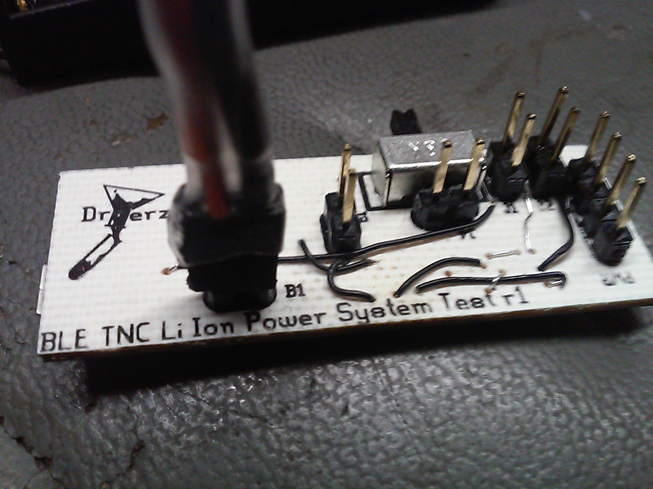
I designed a test power supply board with some jumpers to try and figure out what the best way to build the circuit would be. I added a 3.3v LDO regulator for USB power and figured I could just disable the AS1337, but upon further inspection of the datasheet I found out the disable mode had some properties that would screw me over. There are 2 models of the AS1337. Model A goes open circuit and puts battery voltage on the output when disabled. Model B shorts its output to ground when disabled. Neither was conducive to my design so I added a P-Channel Mosfet to actually shut off power to the regulator when USB power is connected.
This is where things went wrong. Unfortunately I forgot to check the Gate-Source voltage threshold when I selected a FET for the application. For it to work with a Alkaline cell I needed a Vgs(th) of less than 1 volt but I selected one that was 1.5-3.0 volts.
After some fiddling around on the board with the voltmeter and some tweezers I figured out the problem. I tried bypassing the FET with the tweezers and got a beautiful 3.3 volt output with the Alkaline, Li-Ion and USB power. I also tested 5 volts directly to the device but unfortunately this caused the output to jump up to 5 volts. It couldn't regulate the 5 volt input. Fortunately it didn't damage the chip.
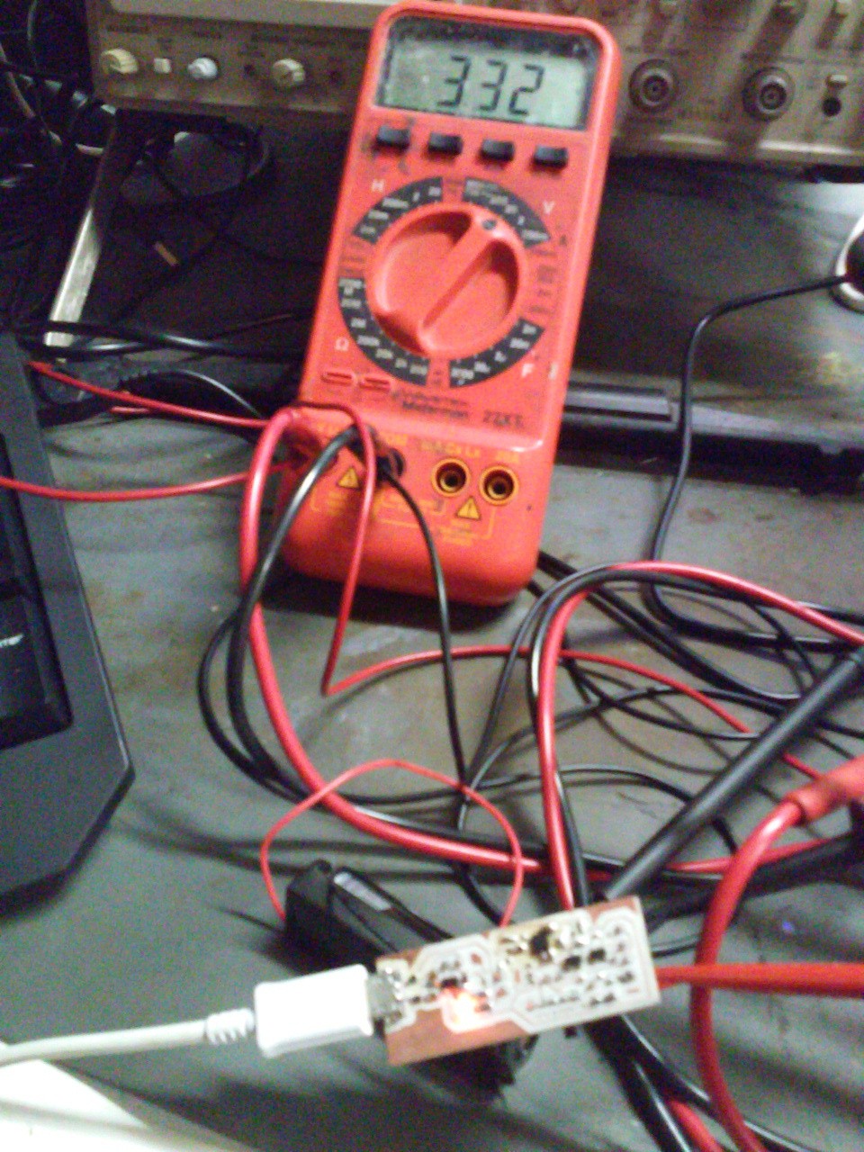
It was surprisingly hard to find a Low Vgs P-Channel Mosfet in a SOT-23 package but after a bit of searching I settled on the MCH3383. Hopefully when it gets here everything will work.
Interestingly enough the -4.2 Vgs from a 10k to ground was not enough to turn on the FET either. I had to ground the gate with tweezers to get it to turn on with the Li-Ion installed. This wasn't enough for the Alkaline. I will probably have to rethink my resistor selection as well.
And if anyones interested here is what the TNC layout is looking like so far.
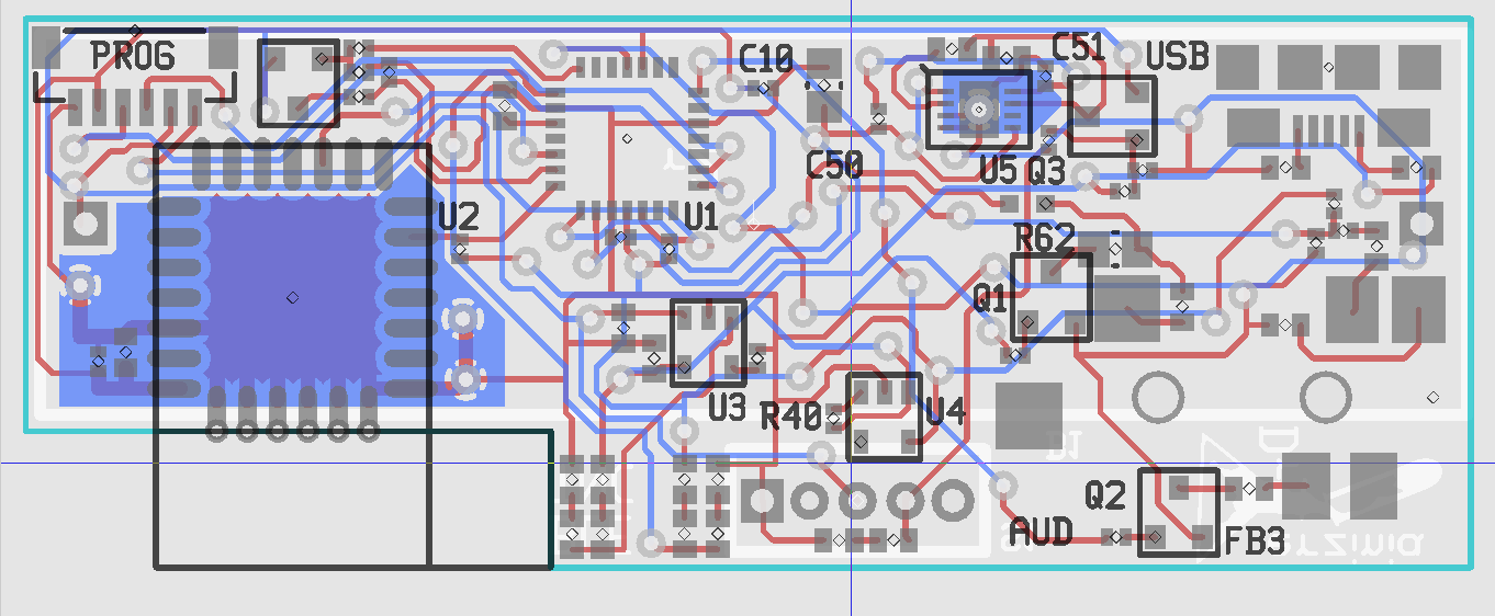
I'm using 25mil via holes and keeping them out from underneath parts to make it a bit easier to make the board at home. I just got a new Jewelers Drill press and a bunch of tiny rivets for PCB prototyping so I might even try using 13.5mil vias for the final version.
I changed from a SIP pinout for the programming header to a 1mm pitch rectangular connector so it could double as a GPS connector. I matched the pinout to the GP-635T. If anyone wants to make it a stand alone beacon with no need for a BLE capable master to tell it where it is they can populate this connector and add the GPS!
I'm also thinking of adding another connector footprint that will allow CAT control of the radio using a shared UART with the GPS.
I'm also hopping I'll be able to make the firmware decode 9600 baud packet from various radios discriminators outputs. As it stands I know it can modulate/demodulate 1200/300 VHF/HF packet schemes. I want it to be as capable as possible.
That's all that's been going on this last week. Hopefully I'll have a post with good news on the power supply design sometime next week with the new Mostfet and Resistors.
Over my vacation to New York I programmed the PIC controller to interface with the AMS002 module instead of being controlled over the serial port so I could test it using the Android app. This ended up being extremely easy. The only change I really had to do was change the error message from ? to str this way it would switch the BLE device into stream mode on any kind of error and I could talk to the phone.
The Android side of things was also very easy. Transitioning to the TruConnect interface of packets containing a serial stream just required some minor tweaking of loops. Then I just had to change it to use Base64 encoding an decoding which already exists in the Android utility library.
In my initial testing I saw you could configure a custom Service UUID in the TruConnect Service. I tried it once changing from the default service UUID 175f8f23-a570-49bd-9627-815a6a27de2a to a randomly generated one (53f06320-d9d2-11e4-8830-0800200c9a66). However even after numerous power cycles I was unable to get it to use the new service ID and changed the app back to the default one as well as resetting the UUID in the flash memory of the device. Or atleast so I thought. I may have forgotten to do SAVE command to commit the new UUID to memory. Either way the observed behaviour is quite puzzling. I used the app with the radio for several days and it worked fine. But this morning I got nothing out of it. Interestingly enough I found it was using the new UUID I had given it several days before and given up on.
I really have no Idea how this happened. But it certainly is something to watch out for if you are using these modules and plan to program custom UUID's into their firmware. It may not work when you try it and then days later start doing what you asked!
Going forward I plan to design and order the prototype boards for the non breadboard prototype by the end of this week. Typically I get board back from OSH park in about 3 weeks so expect some pictures of the prototype then. While I'm waiting on the boards I plan to work on the android app. Shining it up from the raw test program it is into a actually useful APRS app that can be as simple as a locator beacon to as advanced as a full fledged Digipeater, IGate, tracking station.
I got the AMS002 modules from mouser today. Managed to design, etch, and solder a breakout board for it between work and catching a red eye to New York.
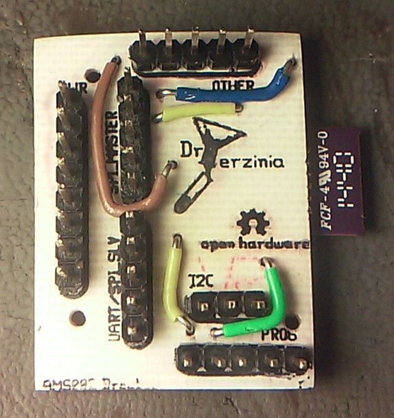
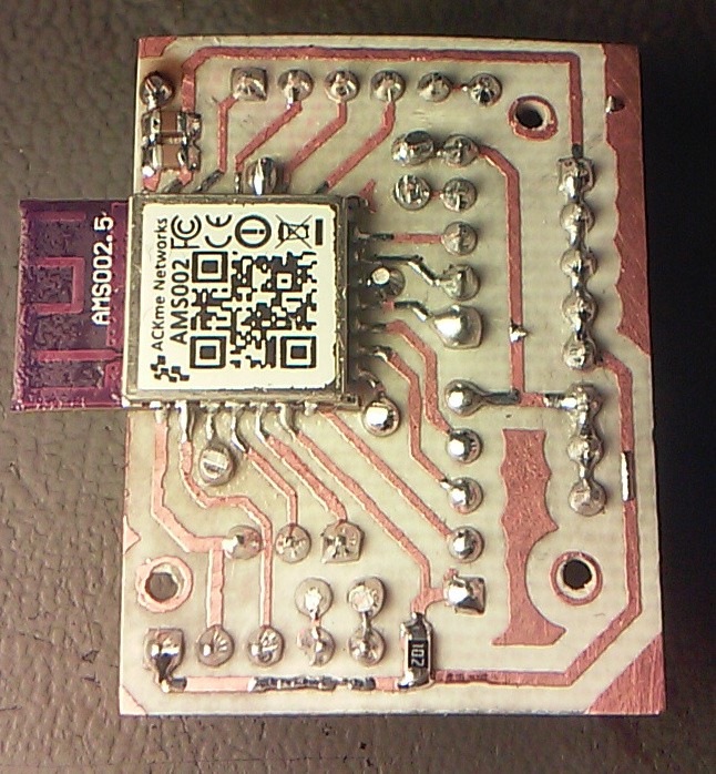
I broke out the pins by functional group rather than just a bunch of long headers by position. I managed to power it on to see if I could connect to it and enumerate the services. It worked perfectly. Should have it tested and talking between the PIC and the Android app in a few days.
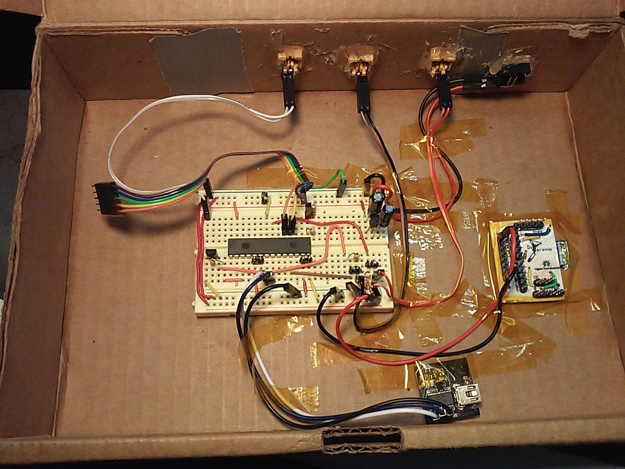
I was debugging problems with the code for 16 hours yesterday. Right after my optimistic log post I noticed a few problems with the code and fortunately after staying up till 4 AM figuring them out I can be optimistic again. This post is just going to be about last nights debugging session.
The most critical problem I encountered was that no demodulators besides my own would demodulate the signal from my modulation code. It baffled me for about 3 hours. I played with the signal in Audacity trying to figure out what was different between my output and the output of another piece of APRS software. In this case APRS Droid. I adjusted the timing, tried adding pre-emphasis, compared both waveforms in spectrogram mode. It was when I was trying to add more pre/post ambles to the signal that I noticed what the problem actually was. As you can see in the image below my signal (Top) has an extra bit inserted.
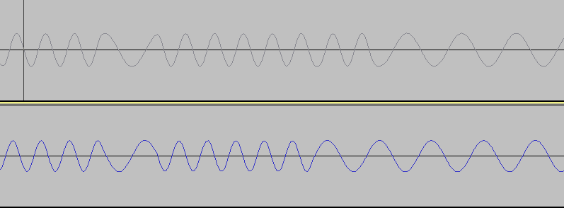
An odd problem for sure. But at least I know why my decoder could still make it out. When it gets a postamble it chops off any extra bits and returns what it has so far. Apparently other decoders aren't so flexible or forgiving. Ultimately I needed to subtract 1 to the if statement that changes the modulator stage from data to postambles.
// old
if(current_bit >= self.len * 8)
    AFSK_Modulator_advance_stage();

// new
if(current_bit >= self.len * 8 - 1){
    AFSK_Modulator_change_frequency();
    AFSK_Modulator_advance_stage();
}
I'm not sure why I needed to do an additional frequency change but that adjustment made the modulator spit out the right waveform. The timing was also slightly off so I changed the divider of the DAC clock down by one and everything I sent out was clearly decoded. MixW 2.20f showed it at 1203 baud, so slightly off but it seems its within tolerance.The next bug was also rather troublesome but it was primarily a poorly written test that caused most of the delay. I programmed it to use base64 for sending the message data over the UART to and from the PIC. This way the stream can still be managed by new lines and everything is printable. The command I was using to send the packets was:
TX="gqCIpGJk4JaIYK6OrGqukoiKYkBjA/A9MzkwMC4wME4vMTA0MDAuMDBXJCBodHRwOi8vYXByc2Ryb2lkLm9yZy84yQ=="
It's the test data I got from APRSDroid to figure out what was wrong with the modulator. My first send naturally was not decoded because of bugs in the base64 decoder. The hex my demodulator spit out didn't match what was expected. Turned out to be a simple case of using a back slash where I should have had a forward slash as well as adding the wrong number in one of the if statements to decide what value a character should have. These problems where both fixed in a few minutes.
What ended up really getting me was a mistake I made in writing a unit test for the base64 de/encoder. I used python to convert the base64 to its binary equivalent and then copied that to the C unit test into a const array.
"gqCkpkBA4paIYK6OrGfwA1Rlc3Rpbmc67w=="
'\x82\xa0\xa4\xa6@@\xe2\x96\x88`\xae\x8e\xacg\xf0\x03Testing:\xef'
Unfortunately when manual converting the \x to 0x I also inadvertently deleted the ' and the g. The 2 printable characters mixed in with the hex. Stupidly I analyzed my code for about an hour trying to figure out how the test could be failing and I was missing 2 bytes in my decoder output. Eventually I realized the mistake.
So I got bitten by unit testing twice yesterday. Because my unit tests for my modulator showed it working because my demodulator is more flexible than others. And by mistyping the expected result into the base64 unit test.
Moral of the story is double check your unit tests.
As for the current status of the project. I was hopping to get the AMS002 modules today but still waiting on those from Mouser. The prototype is tested receiving from and getting into the APRS network successfully. The code has been reorganised a bit and I feel its easier to follow and maintain. The serial command interface for the PIC has been improved using standard...
Read more »After a lot of debugging and testing the current state of the hardware design I decided I needed to go back to the drawing board. I was having a major problem trying to get TX data over the SPI bus to the pic. I don't have a proper logic analyzer, but I did try a lot of things to figure out what was going on and after several days of fiddling around with it I'm still stumped.
However it looks like it's all for the better. My new design uses a dsPIC33FJ64GP802 as its core. It has a built in Audio DAC which fixes the problems with the 2.2k PTT resistor loading down the signal because it has built in reconstruction filters and output drivers. So there is no longer a need for an external low pass filter or driver op amp. In addition to that now that all the processing is happening on the PIC im free to choose a cheaper lower power Bluetooth Low Energy module. The new PIC costs about $4.30 more than the old one but the new BLE module I'm looking at (AMS002), only costs $5.86 starting at a minimum of 1 module. The RFDuino cost $14.99 for a minimum of 1 and $12.79 when you get to the 500 unit volume. This lower's the overall cost down to about $15 a board. So we will also be cheaper than before.
So far I have the PIC sending and reciving APRS packets no problem on a breadboard. Better than what I had before. (RX Only) I dont have the Bluetooth Low Enery modules yet but they look very solid and have a simple serial interface for communication to the master device.
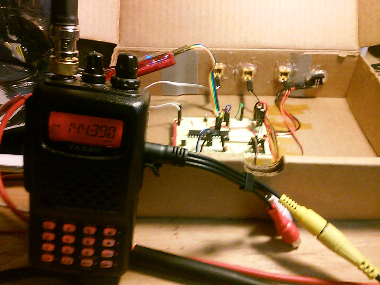
One important point about this design. I've looked around a bit have have yet to find a TNC that works with iPhones or iPads. I believe this is primarly because of the lack of Serial Port Protocol capability. There are apps out there that will use the phones headset jack to get the radio data and to the modulation but I would imagine that would put a significant drain on the devices battery. This device because of the low enery aspect will be able to communicate with iPhones and iPads. There are test applications for the ACKme modules available on the app store so I'm quite sure its doable. I however do not have any apple devices so I will most likley not be writing and app to communicate with this device. If anyone want's to write an app for the iPhone/iPad to communicate with my device or has an APRS app and would like to integrate compatibility with my device in addition to the headset modem send me a message.
Things are looking pretty great for me to have a fully functional prototype ready to show off in about 2 weeks. The only things left are to test the Bluetooth LE Module, design and make new board, and finaly tune up and streamline the code and the device communication protocol. Hooking up the breadboard prototype to the computer via serial port allows me to recive and send packets quite well.
Right now I have the Lithium-Ion AA battery powered prototype with RX working. Currently testing TX code on the bread board prototype. RX performance was tested passing recorded packet data directly into the demodulator on a computer from WA8LMF APRS test CD with the following results.
Stephen Smith WA8LMF's APRS test CD Track 1 demoded 958 packets
Stephen Smith WA8LMF's APRS test CD Track 2 demoded 641 packets
Will need to test alternate TNC's to see how it measures up but based on these numbers it seems to be doing an excelent job of demodulating packets.
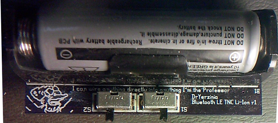
The Li-Ion prototype is just a tiny bit wider and longer than the AA battery that is powering it while remaining relatively thin. Based on TX tests with the breadboard prototype I don't believe I will be able to get good TX performance out of this PCB and will have to wait for the next prototype for good TX. It only draws 7 mA in RX mode giving it an approximately 1 week long battery life.
Testing the TX last night with my Yaesu FT-60D as the transmitting radio resulting in currently disappointing performance. While my attic terrestrial TNC was able to decode every packet after I added some low pass filtering to the TNC I could not get a single packet to bounce of a repeater or get into the APRS network. A test using APRSDroid attached to same radio hit 2 repeaters and got into the APRS network on the first transmit. I'm thinking to use the PIC's built in OpAmp to give the DAC some current gain because the load from the radios MIC input appears to be distorting the signal a bit. Also I will need to check to make sure its not over or under driving the audio input, it sounded clear on a second receiving radio but obviously it is not working well.
I expect to have good TX performance by the end of tommorow night. Hopefully I can finalize updates to revision 2 of the prototype PCB and have them ordered by friday.
Create an account to leave a comment. Already have an account? Log In.
Bluetooth is one of the most important features of a cellphone and I think, without this feature a cellphone is incomplete. I have also read some great info about his ability to win betting games easily. Cellphones of previous years were a little bit tad from today’s cellphones because technology wasn’t at its peak on that occasion.
You would not believe but I have created my own Bluetooth Low Energy TNC by following the same procedure as yours. Most of the students like to hire professional college essay writers for help in course work online. Now I am able to send and receive modulated packet data on my phone through the radio.
is possible using it as gotenna ?
is possible using ax25 on ICM? for example 433 Mhz not 148
and for example sound modem and baofeng
Become a member to follow this project and never miss any updates
By using our website and services, you expressly agree to the placement of our performance, functionality, and advertising cookies. Learn More
 Tim Wilkinson
 Patrick Van Oosterwijck
 Boz
Boz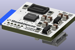
 Matias N.
Girlfriend is the happy girl sitting on top of the boom box. She is a white woman with long hair, wearing a red dress and high heels. Can you conquer her?