-
Assembly and Completion
01/21/2018 at 02:35 • 0 commentsIt's been about a month since I started working on this project, and the time has come to put it together!
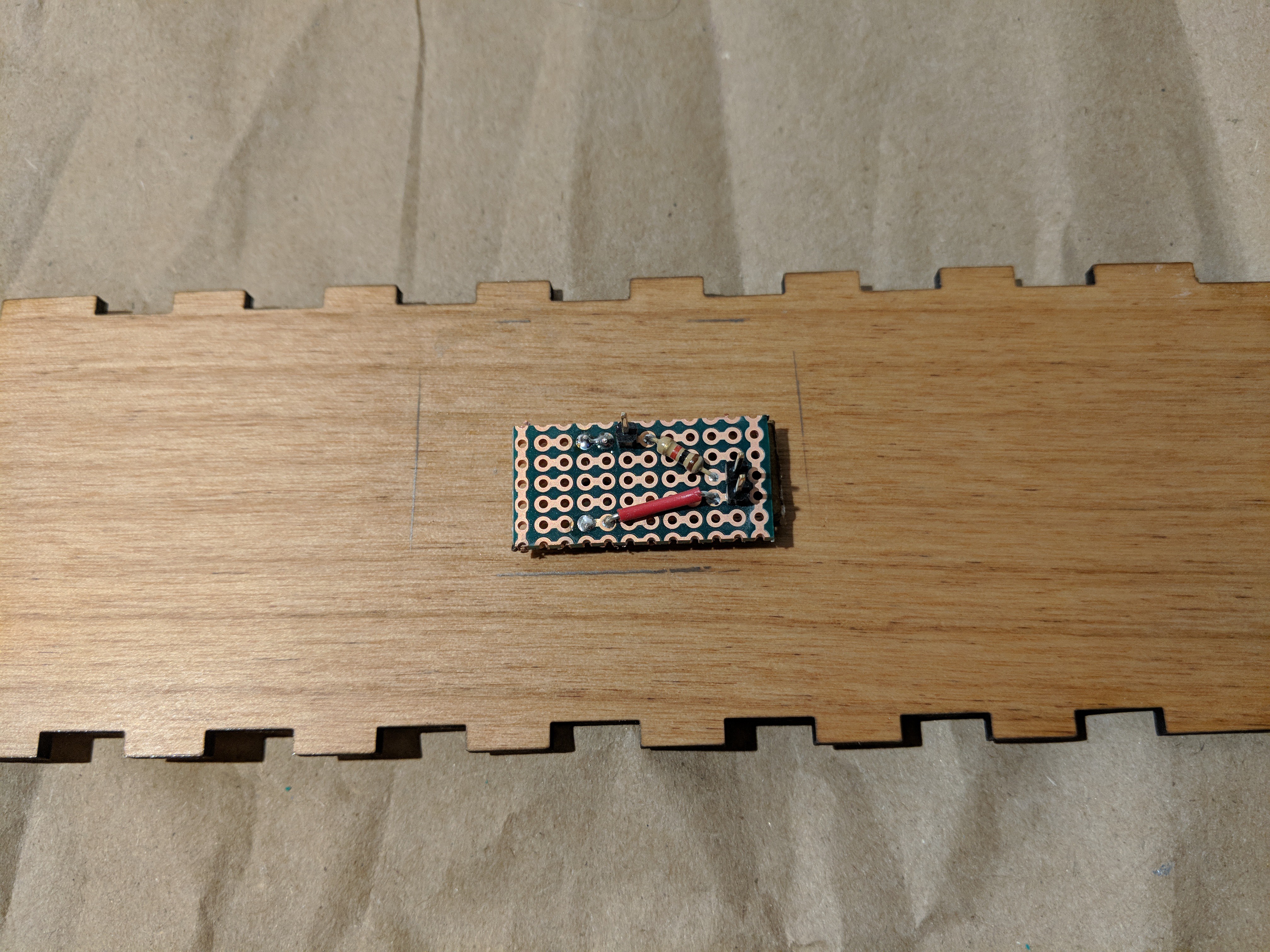
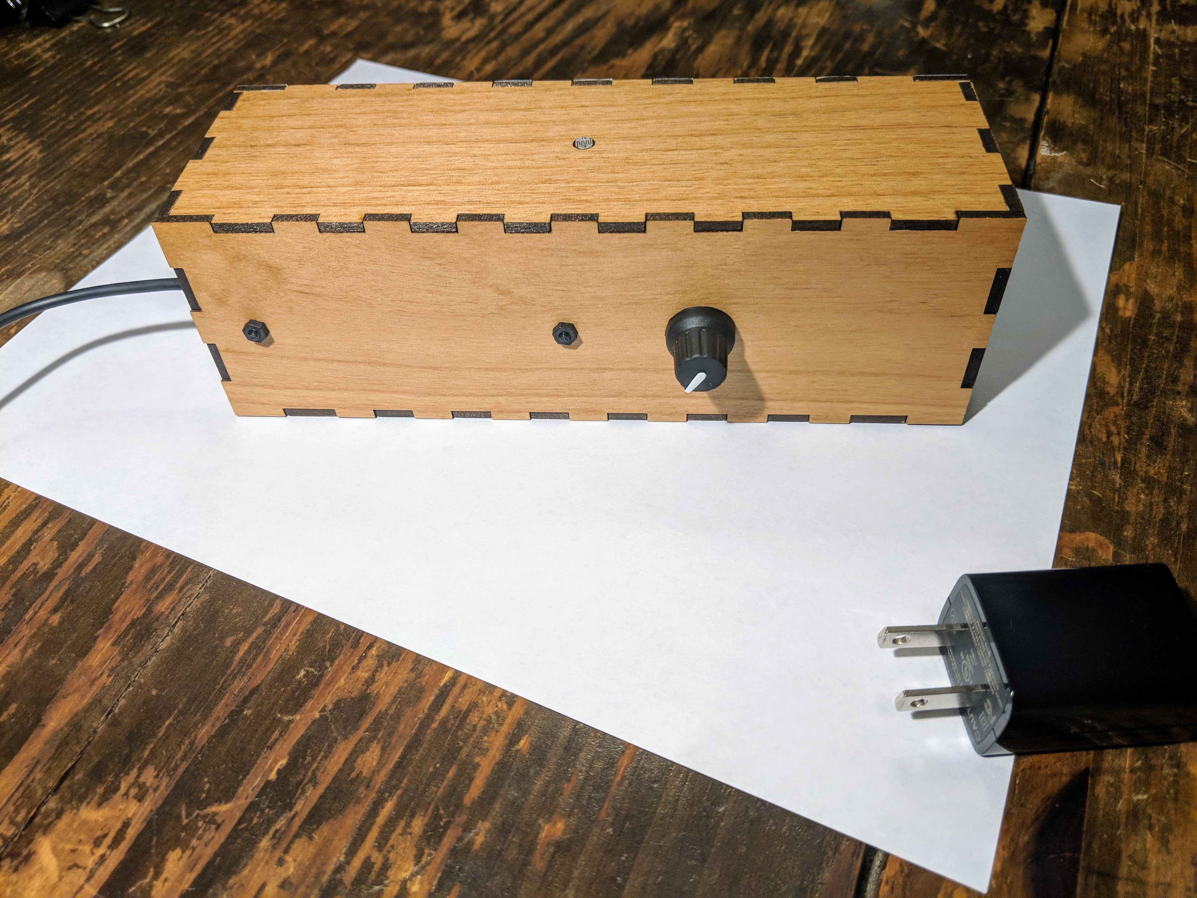
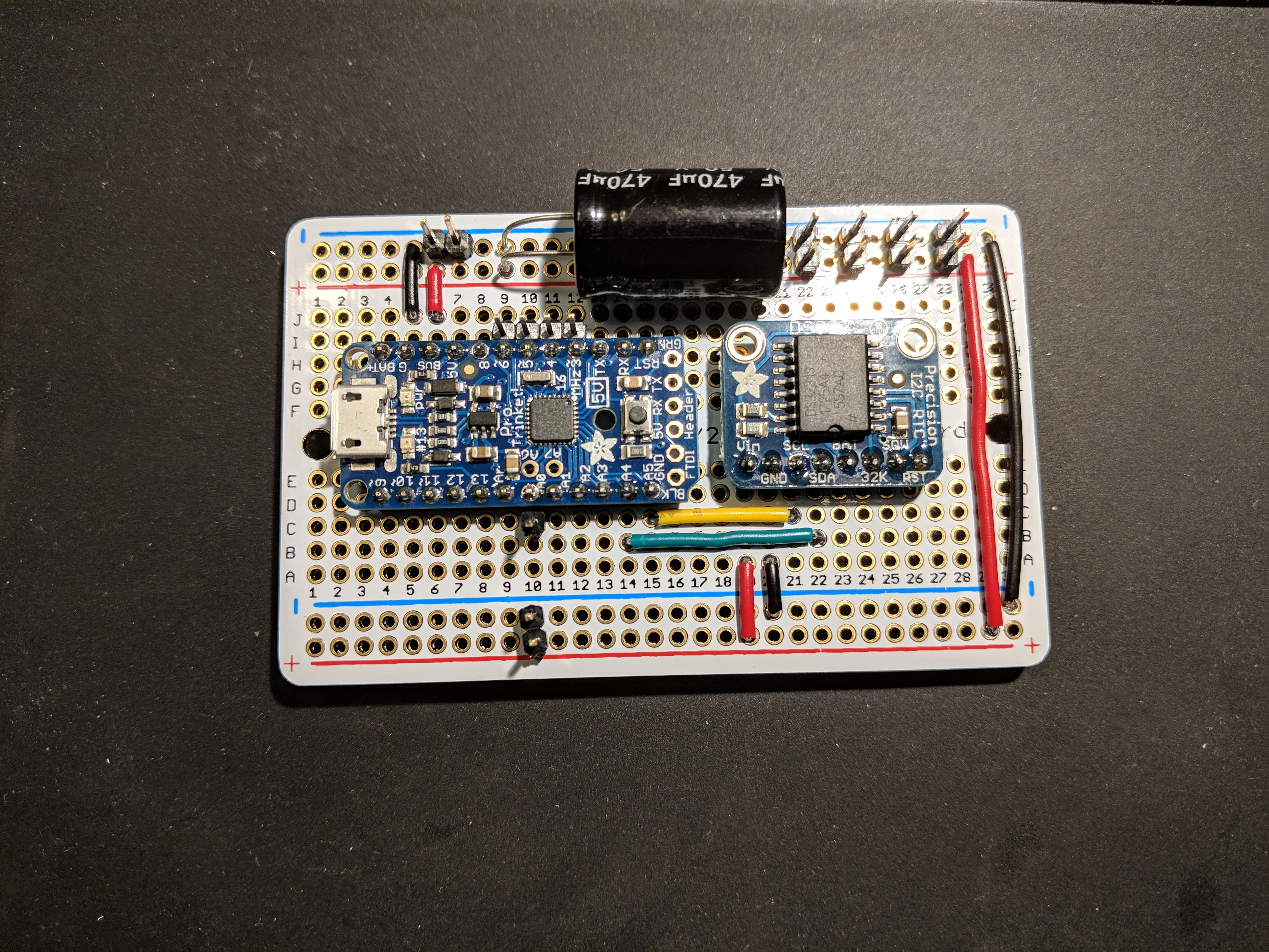
Aside from the main protoboard containing the Adafruit Pro Trinket (5v) and the Real-Time Clock (RTC) module, there are a couple other small boards that support the other functions. One has the rotary encoder which is mounted on the back of the box, next to the main board. The other holds the CdS photoresistor, and is mounted on the inside of the top of the box, with the photocell exposed through a hole. A bit of hot glue keeps that attached, since I didn't plan for a better method.
![]()
If you look around the small board there, you can see a pencil outline that represents the footprint of that board before I took the Dremel to it. I did that after realizing that interior space was very tight, and things were not going to fit unless I accounted for insets on both the front and the back. Whew. Bullet dodged.
Next, I turned my attention to the digits. The digit segment shrouds are made of three 3mm layers of wood, stacked and glued together. Since abandoning my initial plans for a 3D printed enclosure, I've been moving forward with a plan for wood + paper. The thin white paper acts as a diffuser for the light for each segment.
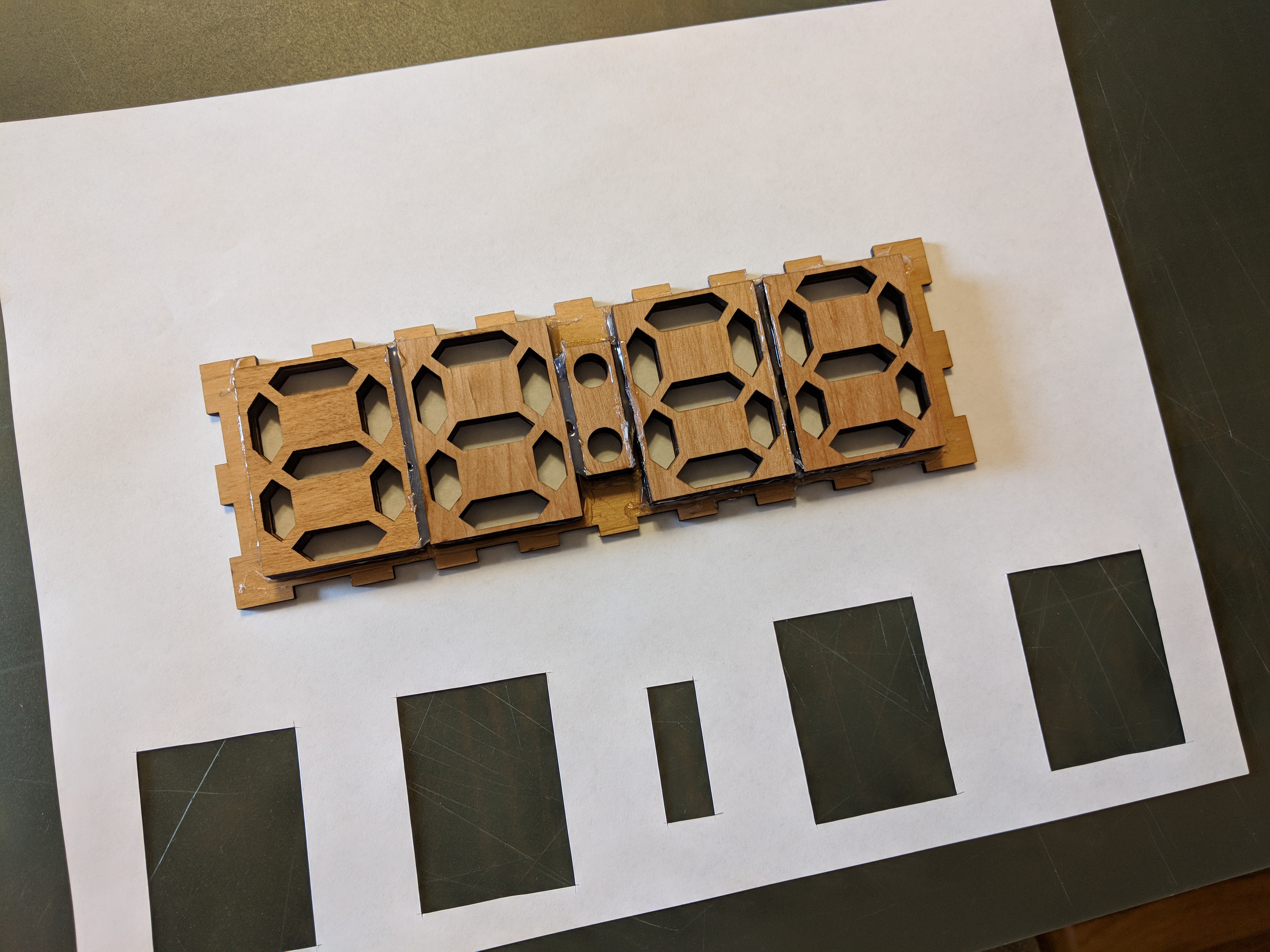
All of my experiments had been considering digits in isolation, so I went ahead and glued (with Elmers glue stick) paper to the front of all my digit pieces. When dry, I used an X-Acto knife to cut them free along their outlines.
![]()
![]()
Now it was time to get these affixed to the inside front face of the clock. Because I didn't really plan ahead with through-holes for all of these mountings, it was back to the hot glue. To make sure that I was getting the segment openings lined up well, I traced the digit shroud outlines onto the faceplate interior before covering them in paper.
![]()
![]()
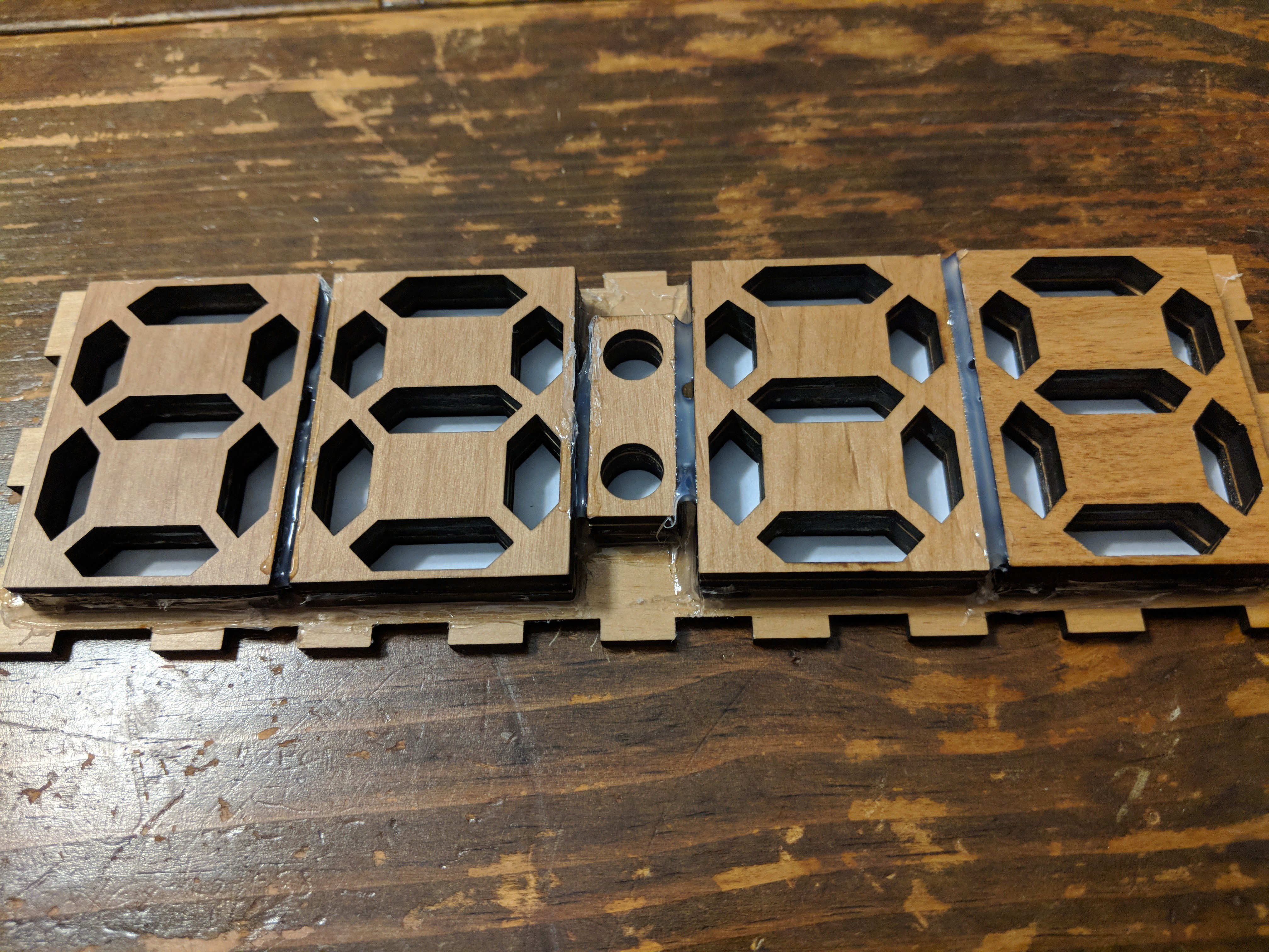
Not super pretty, but not terrible! Using a plastic collar stay to smooth down the glue and force it into the corners was fairly effective. But wait, what's this...
![]()
I should have been extremely pleased with this result, but I wasn't. This wasn't going to give me the look I was hoping for. The contrast of the white paper with the wood is great, but the segments stand too much. Even with some of the segments lit in a color, the unlit white segments were going to be too visually distracting to be an effective clock. This was when I realized that what I really wanted was a smooth, featureless front. My experiments with 3D printed front-faces has this, and so did my individual digit tests with paper. So, now I just needed to figure out how to get that look across the whole front.
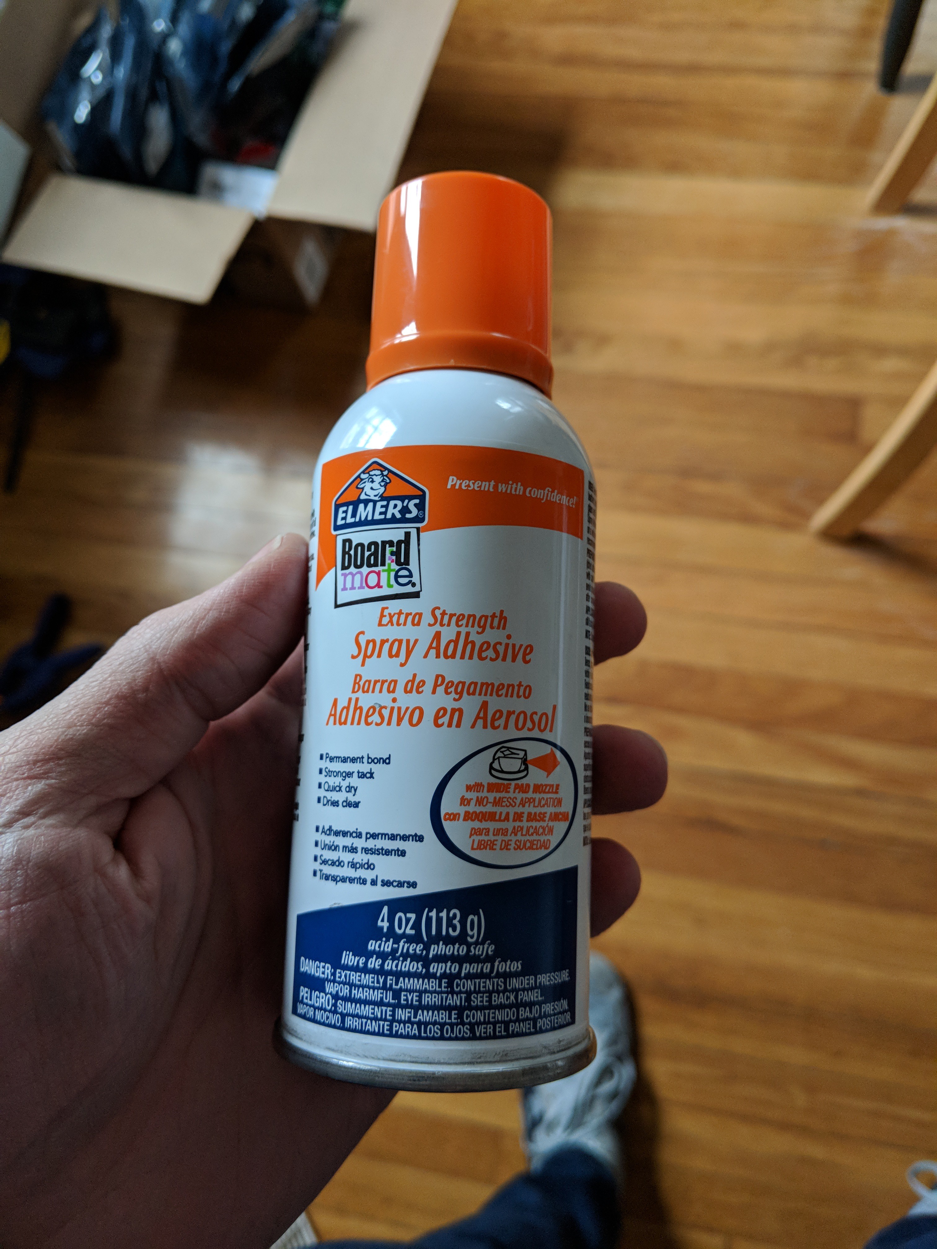
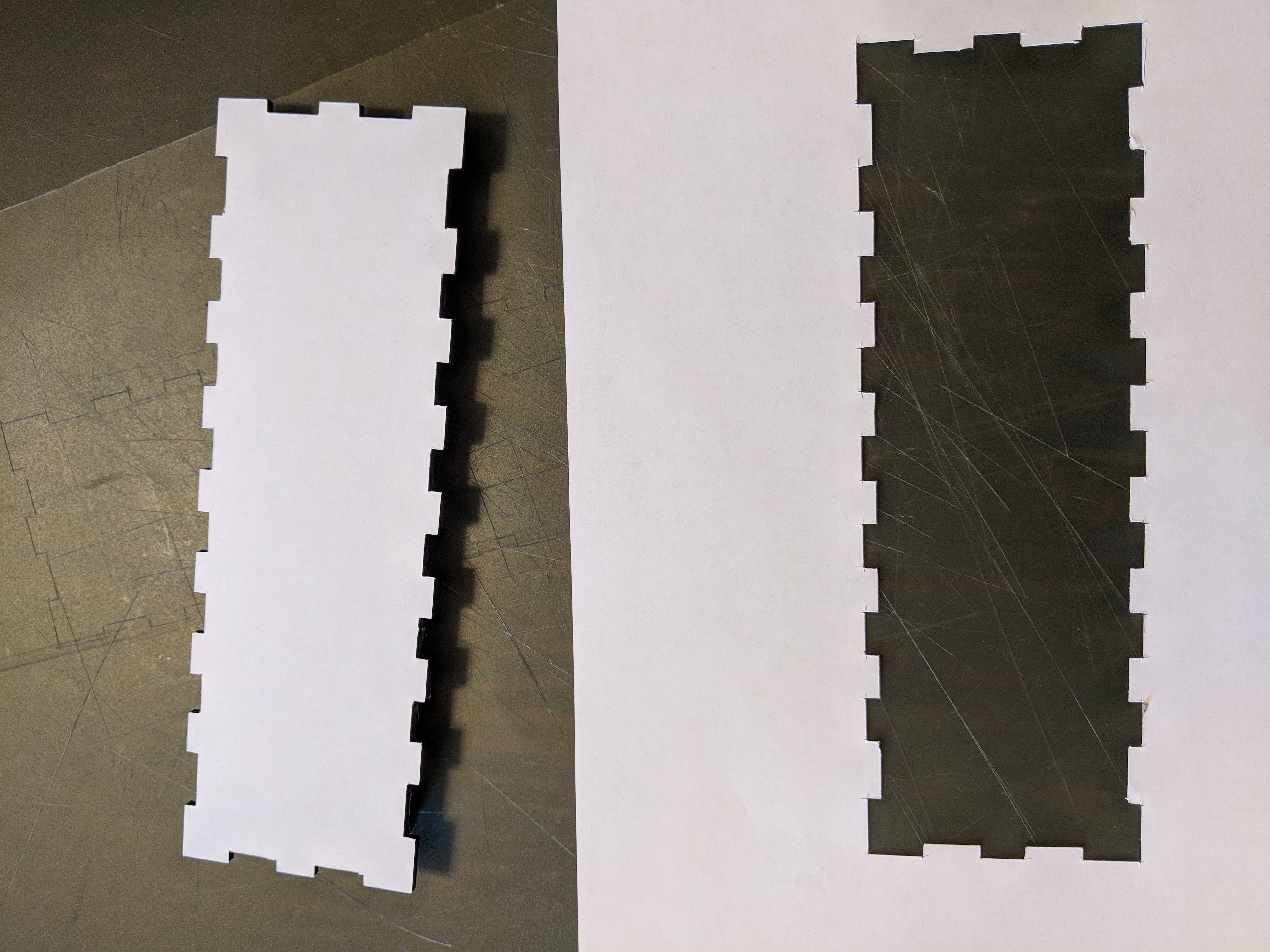
If I was going to cover the whole face of the clock in paper, have it stick, and not look stained, I was going to need a new weapon.
![]()
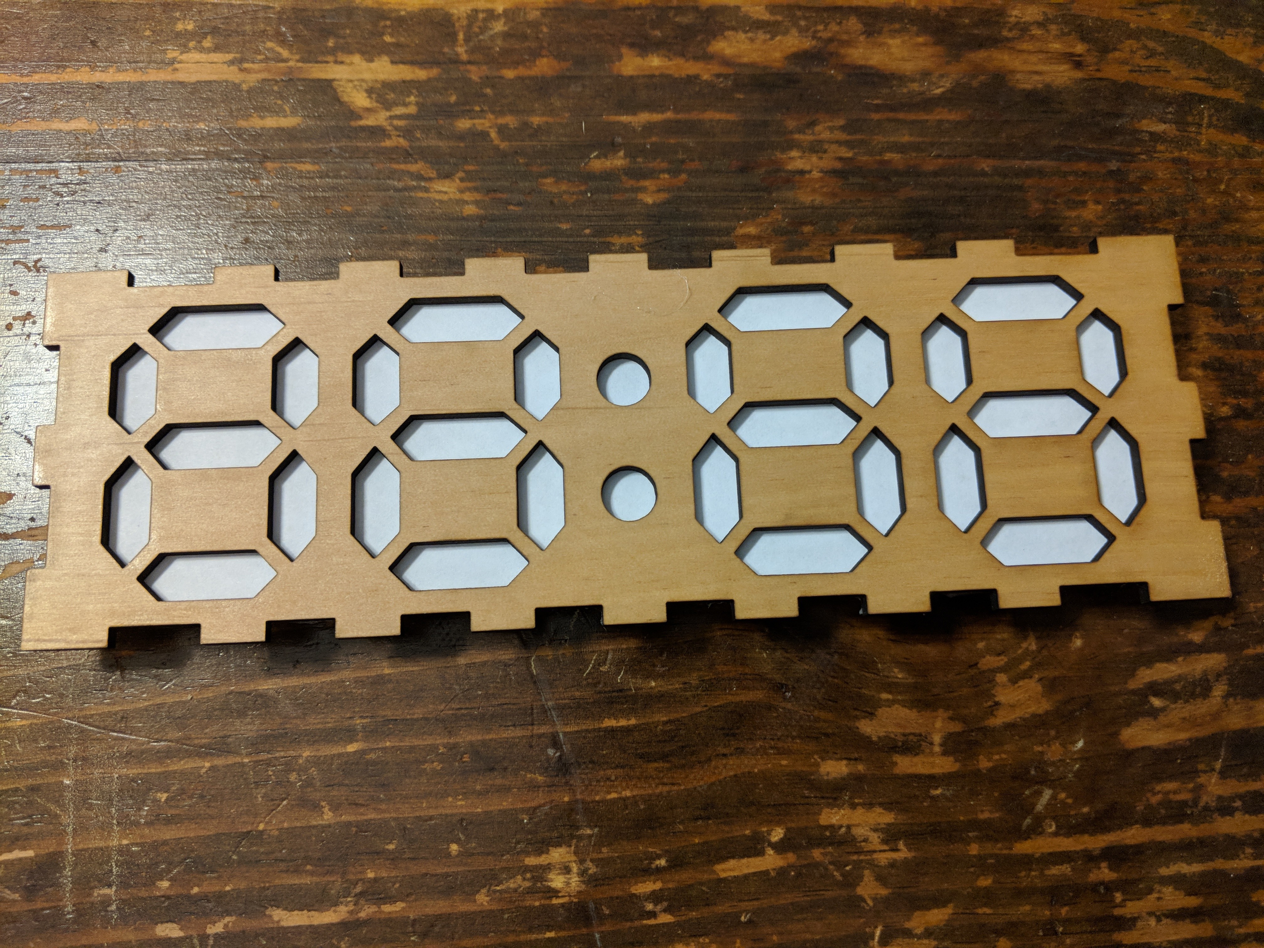
After coating the exterior face of the clock with spray adhesive (sorry, individual paper segments!), I pressed it back onto my paper, and set it to dry under the pressure of some heavy books. A little while later, I grabbed my X-Acto again and traced the significantly more complex outline of the faceplate, cutting it away from the sheet.
![]()
![]()
Nice! The spray adhesive worked great, and all of my corners stayed well attached.
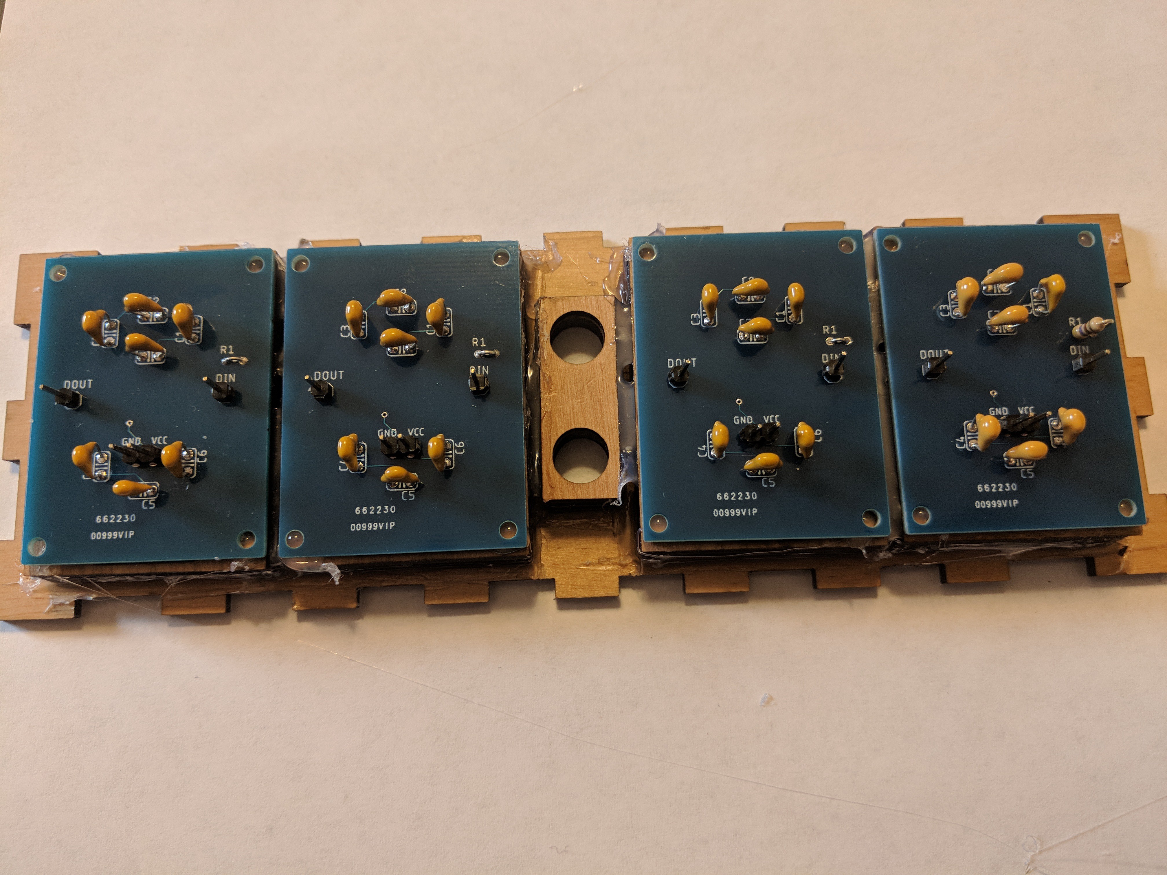
With that, the faceplate is ready to receive some digit PCBs. Fire up the hot glue gun!
![]()
A little dab in every corner got the job done nicely. I hope I don't ever need to get these boards back off! Now, let's see how it's looking...
![]()
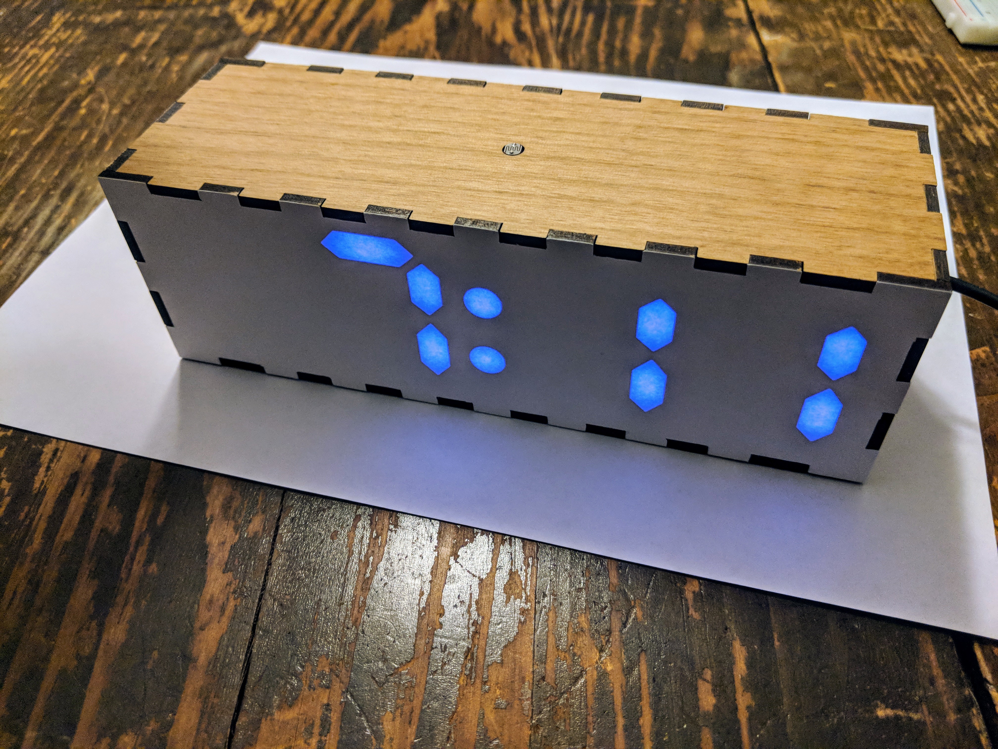
Heck yeah. Nice color, clean crisp segment lines, no distraction from the segments that are off. It just looks like the paper itself is glowing! Let's bring it home...
I brought the box together with some light sanding on all the tabs followed by wood glue on all the interlocking surfaces. The clamps were probably overkill, but made me feel cool.
![]()
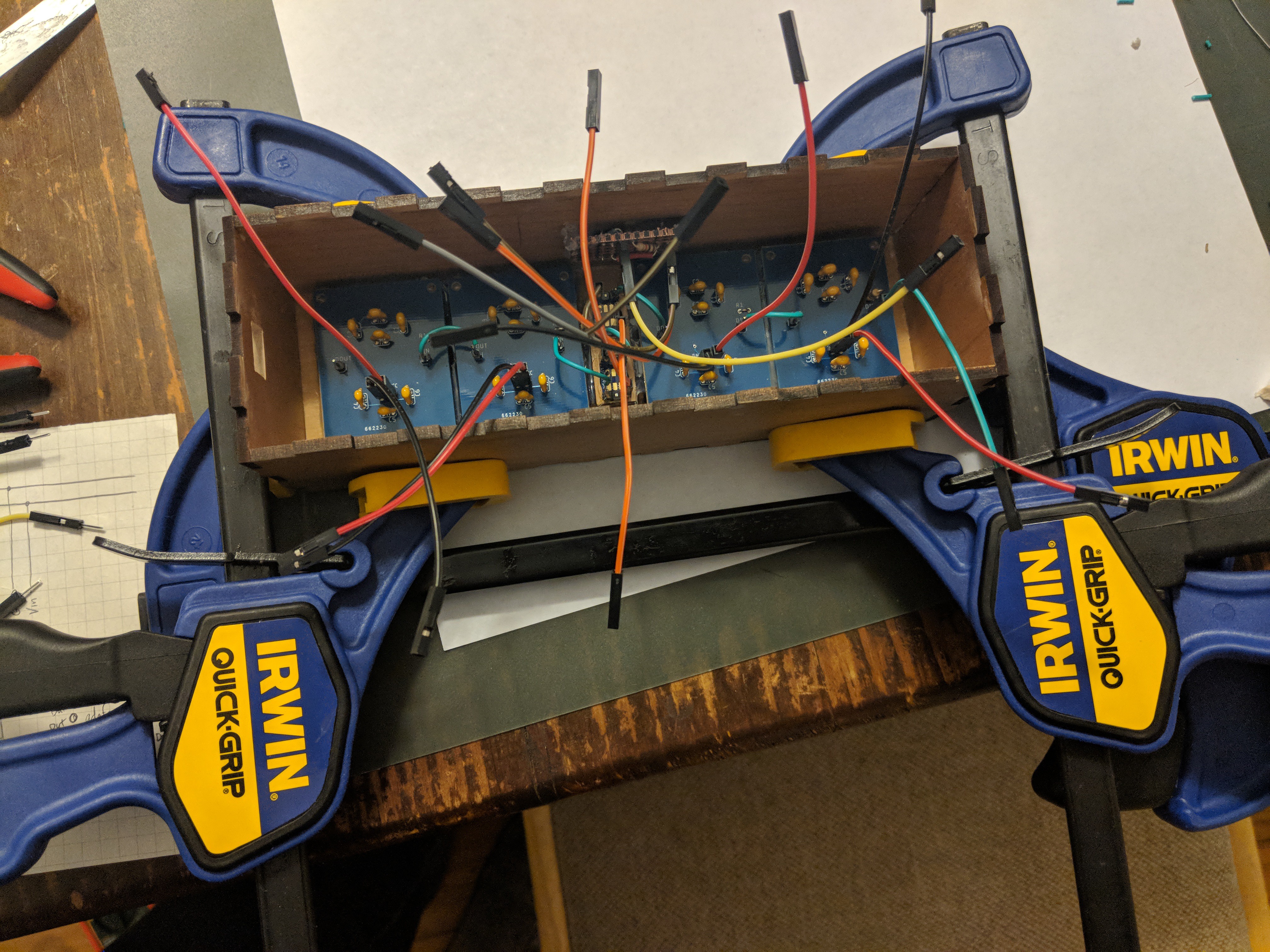
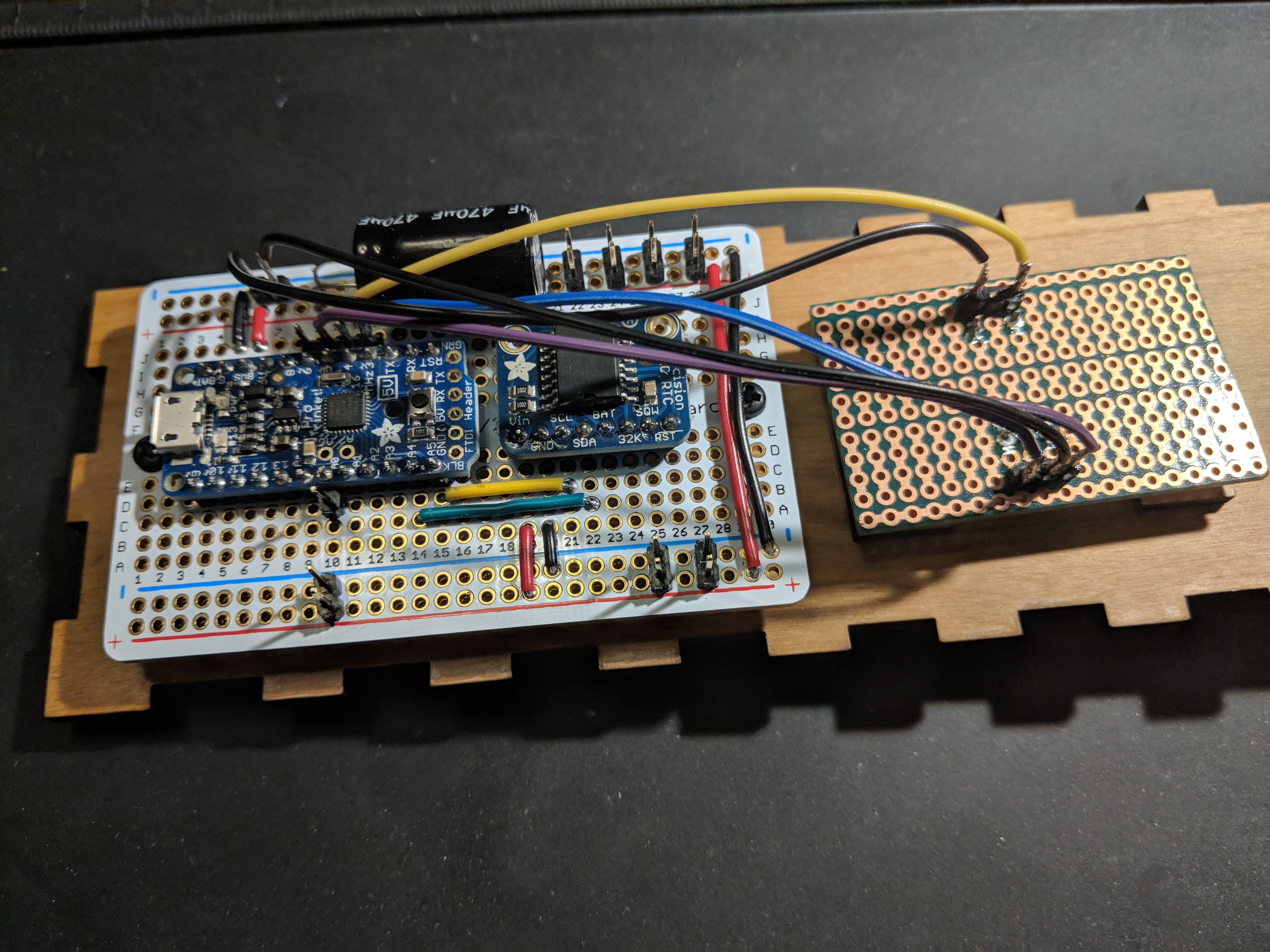
The one last side holds all the rest of the electronics, which I tried to make as compact as possible by removing the header connectors and soldering the wires directly for any connections that were contained to that side.
![]()
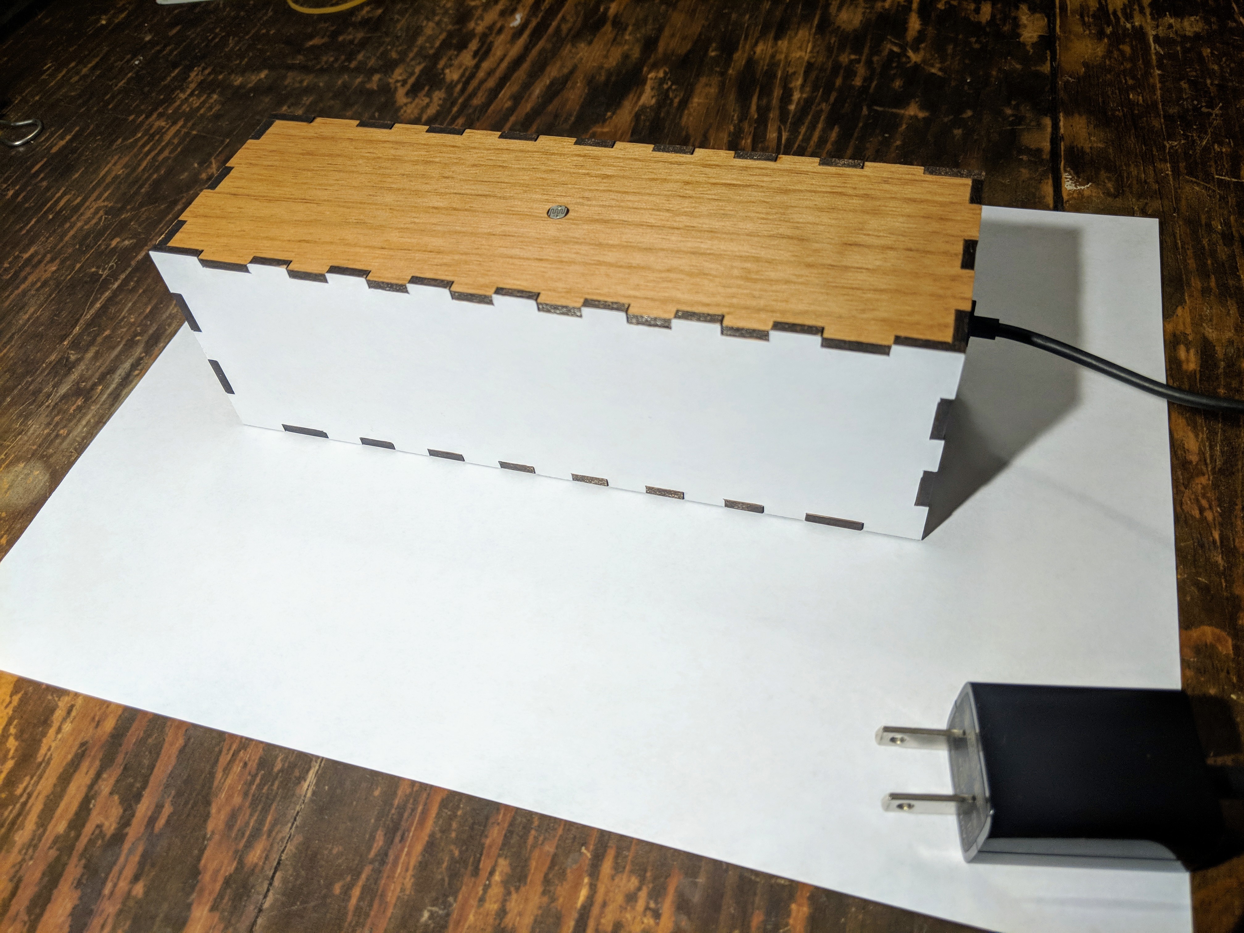
Careful connecting of all the interior wires, a 5V micro USB charger and cable completes the picture, and there you have it!
![]()
![]()
![]()
Looking back, I've learned a ton while working on this project. Before this, I hadn't done any surface mount soldering. These were only the second PCBs I've ever designed and had printed, and they're the first I've used for something real. This was also my first experience with 3D printing and laser cutting/engraving. Wow! That's a lot of stuff for a little over one month, and it sure was exciting.
Thanks for checking out the NeoPixel Clock Mini!
-
Protoboarding
01/18/2018 at 21:47 • 0 commentsWith the parts for the case cut, but not yet assembled, it's time to get the components out of the breadboards and into their more permanent arrangement.
![]()
Despite the fact that I'll basically be gluing the case pieces together, I've opted for a lot of removable connections for VCC, GND and signals. Ultimately I don't expect I'll need to take it apart, but it just felt like it would be easier to get together this way. Also I opted to do the small amount of wiring on the front face of the protoboard. Somehow "showing my work" just felt more "authentic".
Here's a separate shot of the digit modules, roughly as they'll go in.
![]()
There's two more smaller break-outs which will also get connected up - one for the CdS photoresistor (attached to the top), and one for the rotary encoder (mounted through the back).
While I gave myself nice mounting holes on the PCBs, I pretty much failed to plan for getting those mounted onto the front of the clock. Through-holes and long bolts would have given me some real simple assembly for the face, segment shrouds, and boards. However, without the holes anywhere else, and since this project feels like it's been going on long enough, I'm going to opt for inelegant amounts of hot glue to save me. We'll see how it goes!
-
Towards an Enclosure
01/16/2018 at 01:44 • 0 commentsAs I might have let on earlier, I've mostly been exploring 3D printing as the way to produce an enclosure for this project. I started off doing tests with one digit at a time, seeing whether a nice segmented display could be produced from a single printed part. These tests were reasonably successful, so I recently moved on to a complete 4-digit clock-face part.
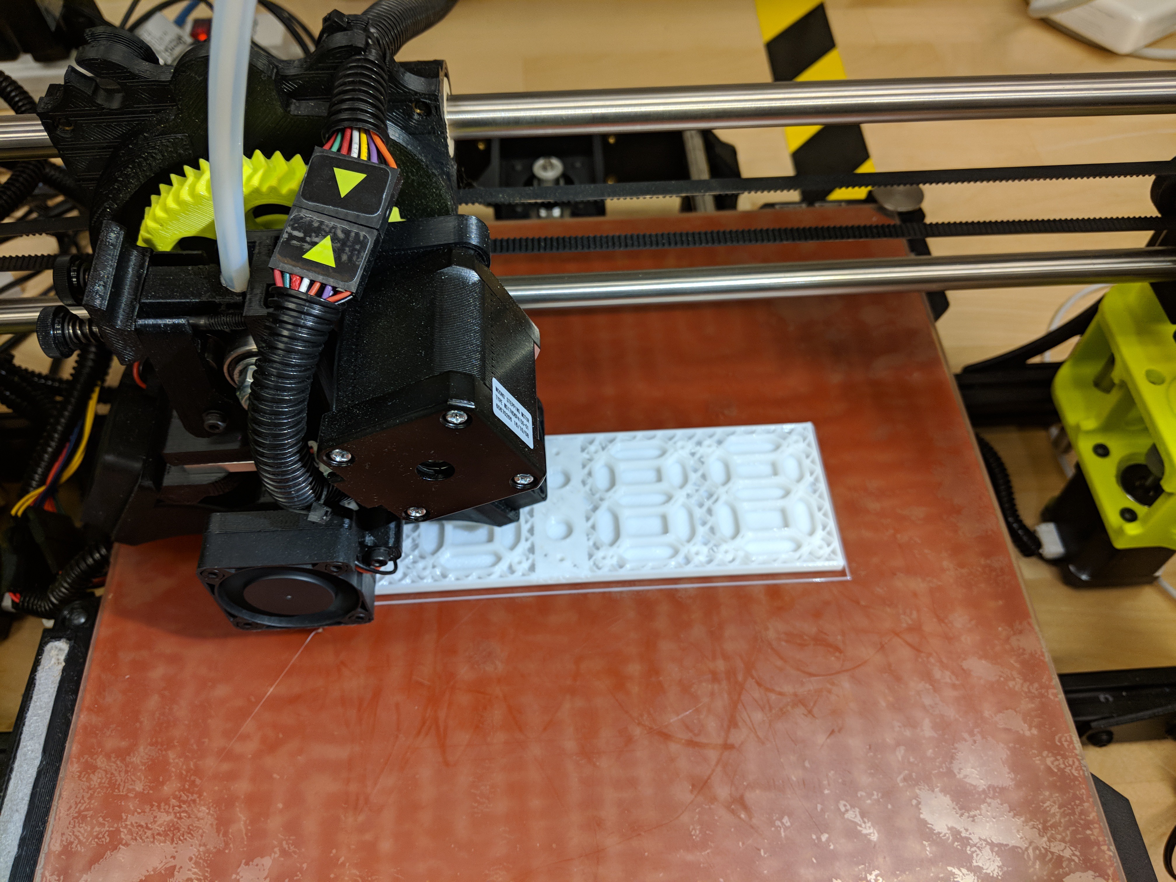
![]()
This print did not go well. It could be the reliability of my shared resource (the printer) or the nature of my design, or a combination of factors. But after a few false starts and a failure 2 hours into a 3-hour print, I started making alternate plans.
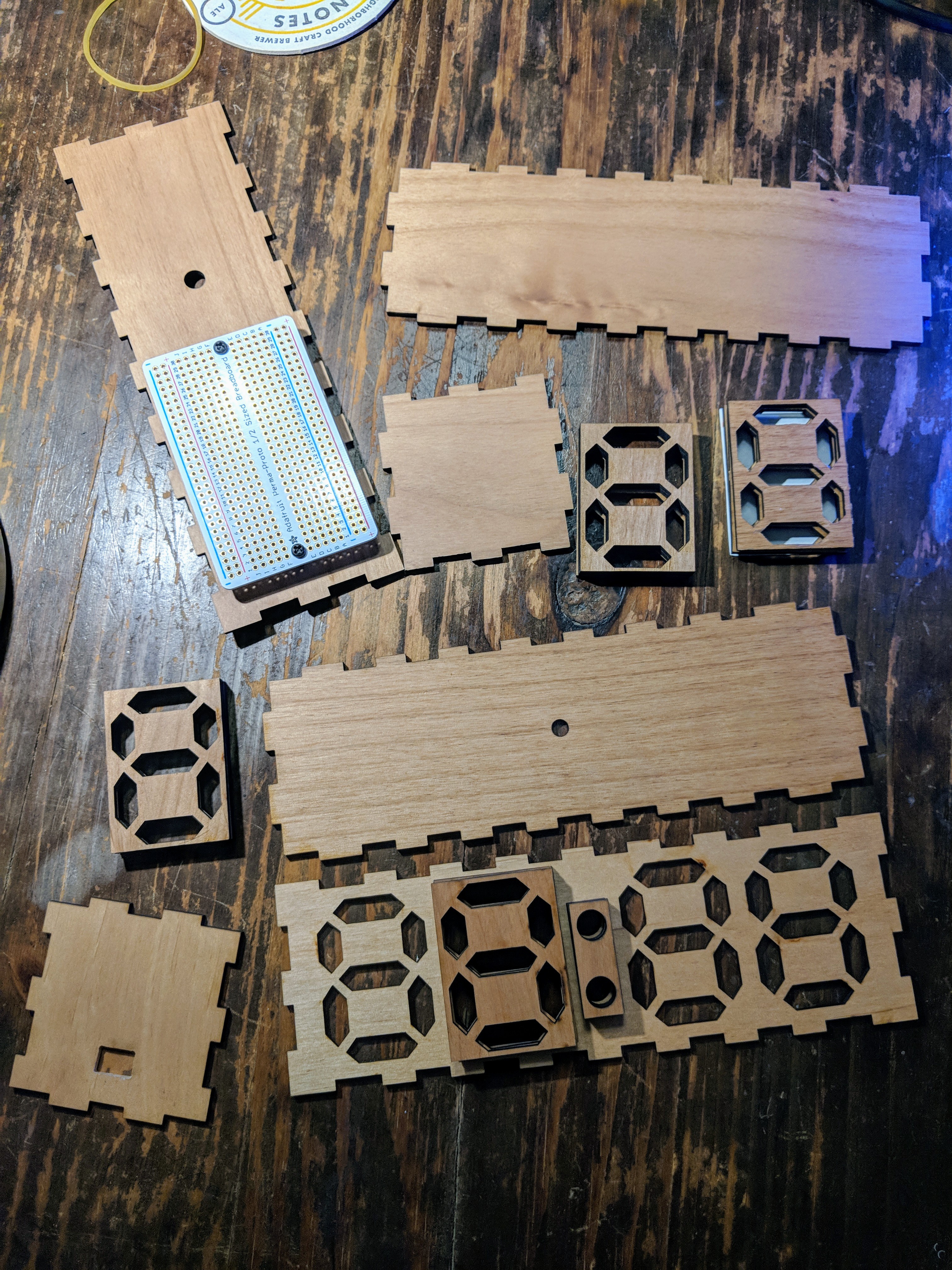
Namely, I started eying the laser cutter/engraver over in the corner, and started thinking, "you know, a wood enclosure would actually look pretty nice." So I bootstrapped a box with http://www.makercase.com/ and then added in the cutouts I would need.
![]()
Not bad! And the laser cutter works much faster than the 3D printer, so I had plenty of time to mess up and try again. When I try this approach again in the future, I should think more about through-hole fastening all these layers of wood together. As it is, I didn't give myself any holes, or much room to drill them. So, the segment stacks and faceplate will be coming together with glue. Hope it holds!
![]()
That said I think the final look is going to quite nice. The laser cut wood gives really excellent definition on the segment shapes, and I think plain white paper may do just fine as a diffuser surface. The combined wood + paper aesthetic will make for a fun contrast with the colorful LEDs!
-
"User Interface" Coding
01/10/2018 at 03:54 • 0 commentsHaving gotten four digit boards soldered, the clock has started to feel more real.
![]()
With the real-time clock module installed and connected in code, I've really just been working on "user interface" code.
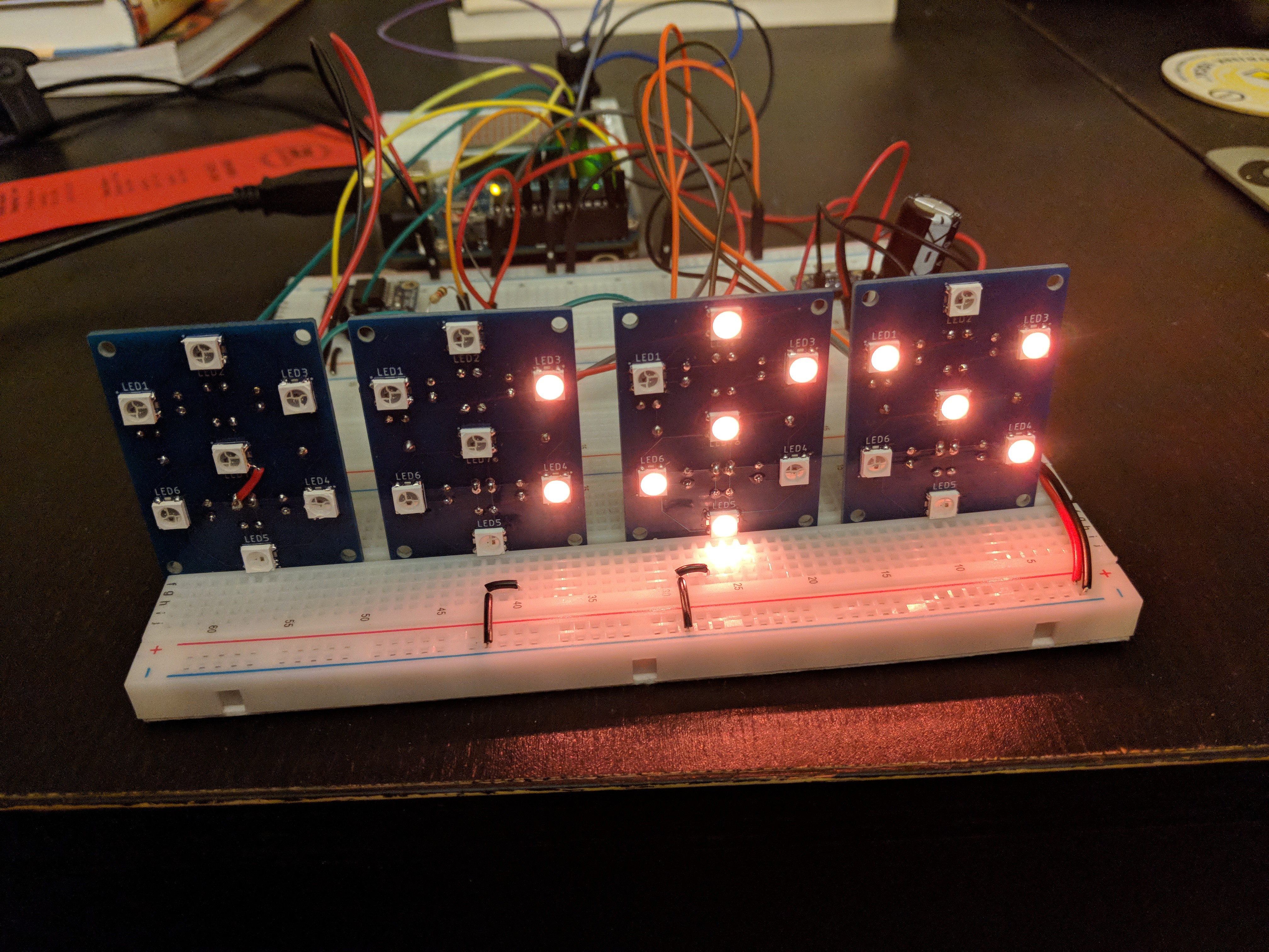
The main idea I wanted to explore with this project was to have a clock that could change color with time. Throughout the day, the LED color will slowly move around the color wheel in a consistent way. So 3pm might be kinda blue...
![]()
but 10pm might be purple (like in the first picture). 1am might be kinda orange...
![]()
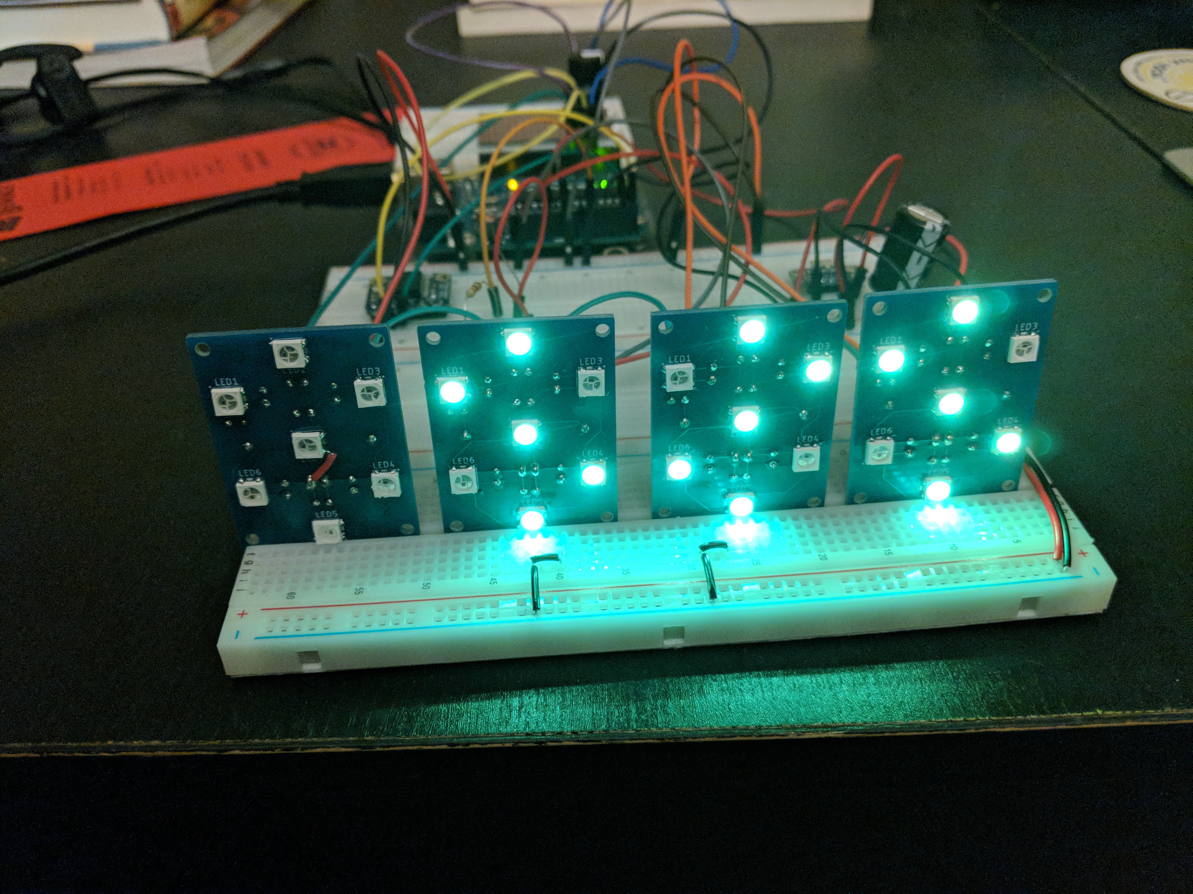
while 5am starts getting green...
![]()
Over time would I start to associate color with time? How would that feel? That code is in place, and I rather like the effect so far.
Besides that, I also reworked the rotary encoder logic to serve its intended purpose of allowing for time adjustment. A blinking animation helps you see what you're adjusting.
I'd like to have a similar fade out/in animation as digits change each minute, but the code is already getting gnarly tracking the existing modes and animations. We'll see what I can do to make it more manageable.
-
The PCBs have arrived
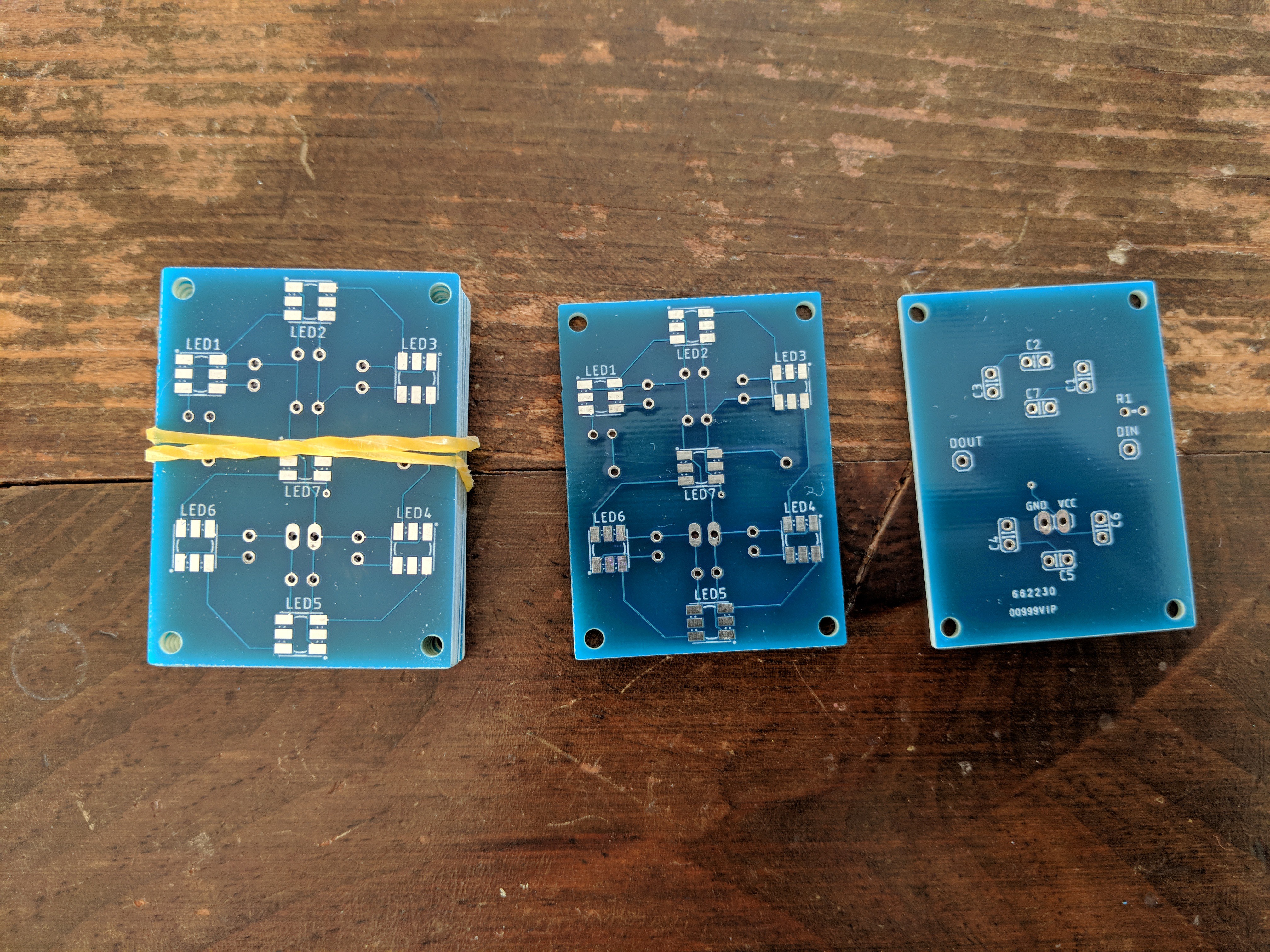
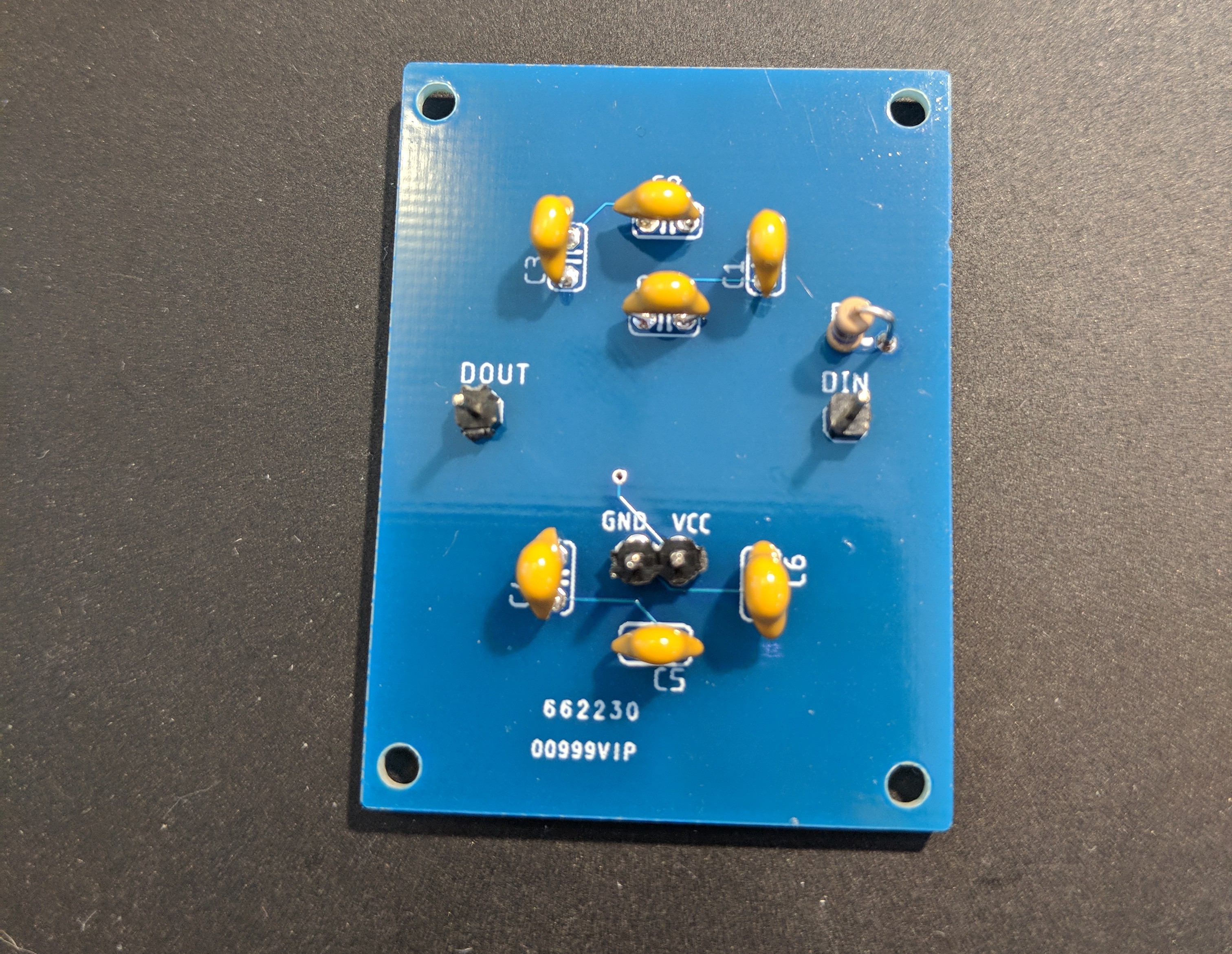
01/07/2018 at 00:45 • 0 commentsThe seven-segment digit display PCBs arrived today from Seeed.
![]()
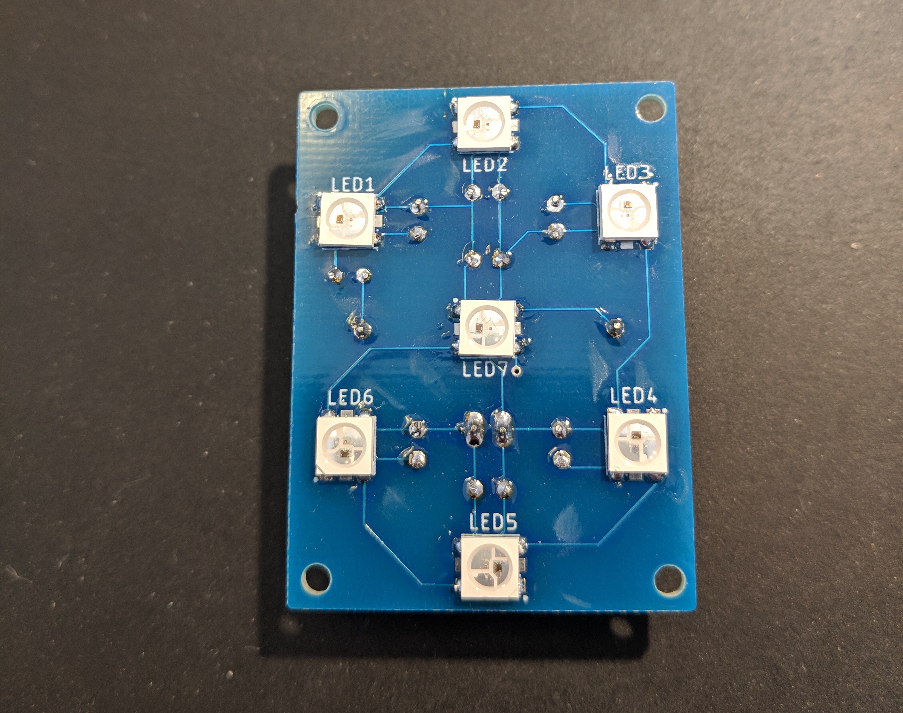
The NeoPixels are the first surface-mount components I've worked with -- everything else I have is through-hole. Thus the odd mix of SMT and THT on these boards. The design could definitely be improved by switching the passive components to also be surface-mount. While all that feels clumsy, everything worked as intended, so I'll call that a win for my second ever PCB design!
![]()
I guess I should also say that I don't have any solder paste or hot-air capabilities either, so all this went together with my Hakko and a T18-S4 tip.
![]()
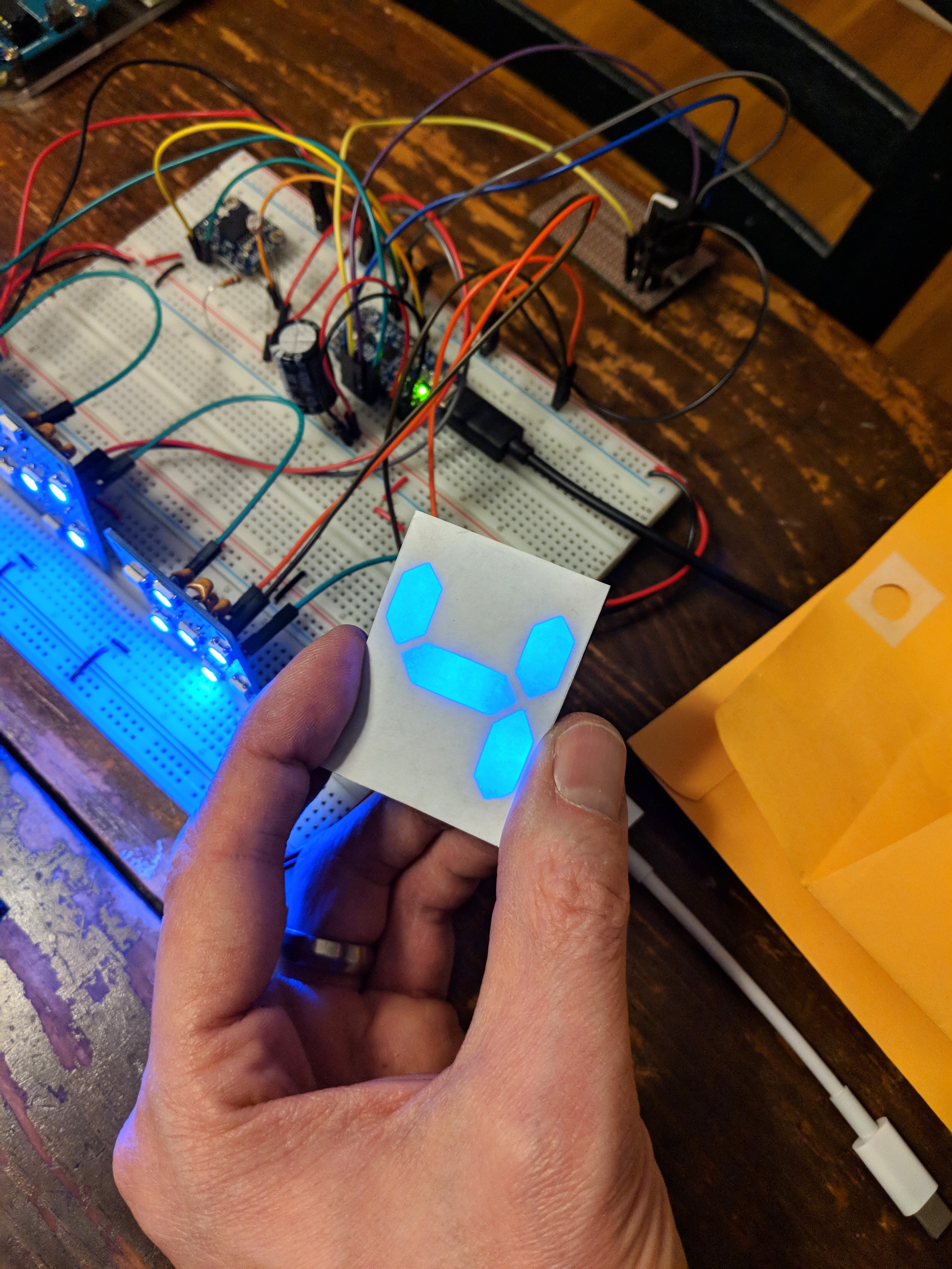
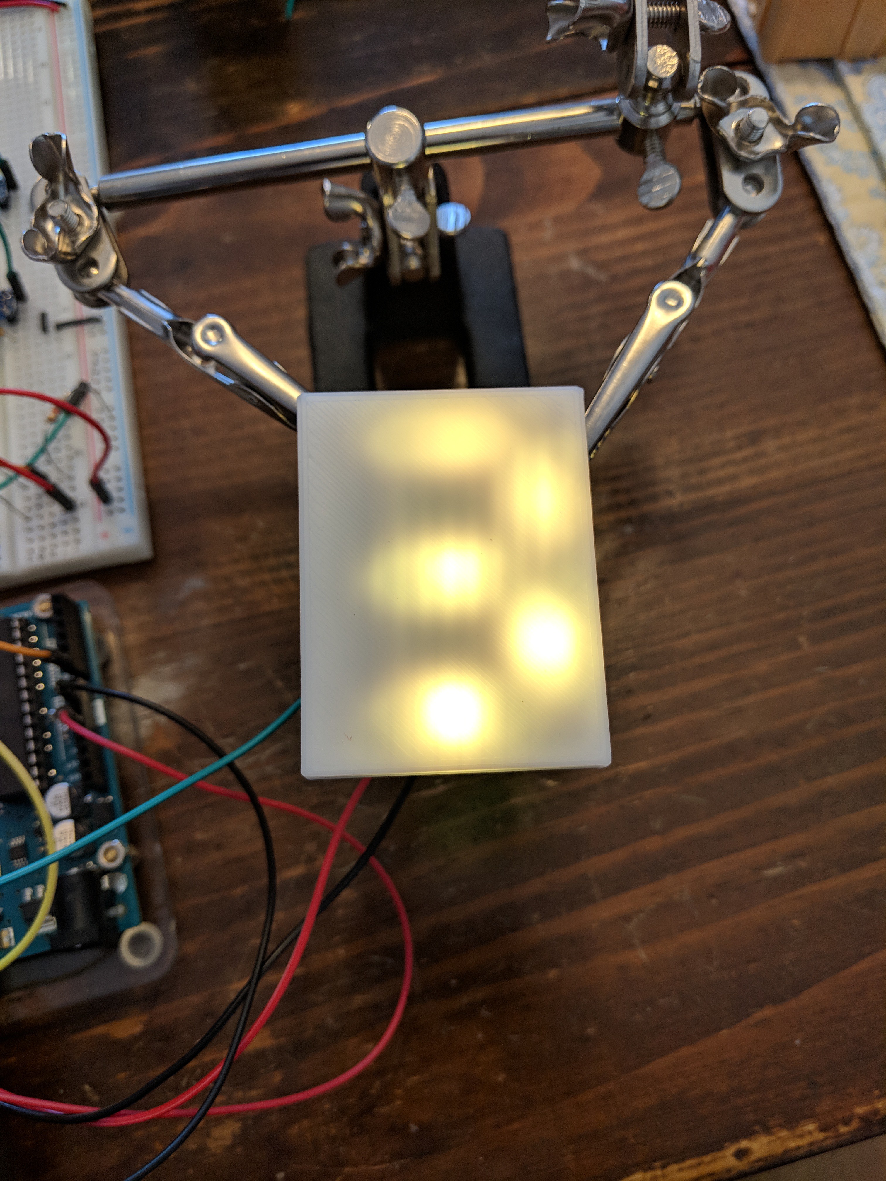
With my prototype 3D printed diffuser laid over top, you can start to get a little clearer of a picture of what these digits might look like.
![]()
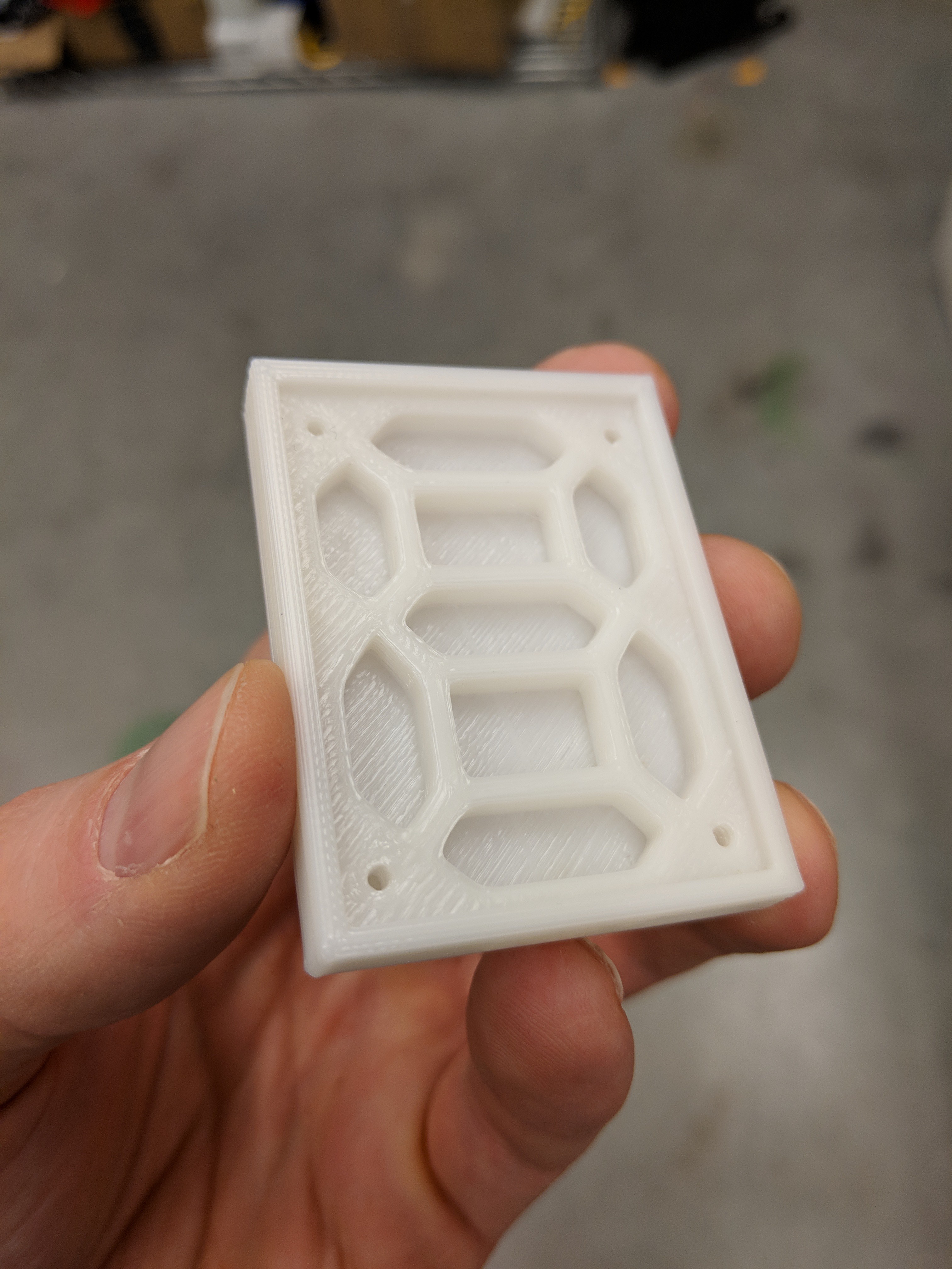
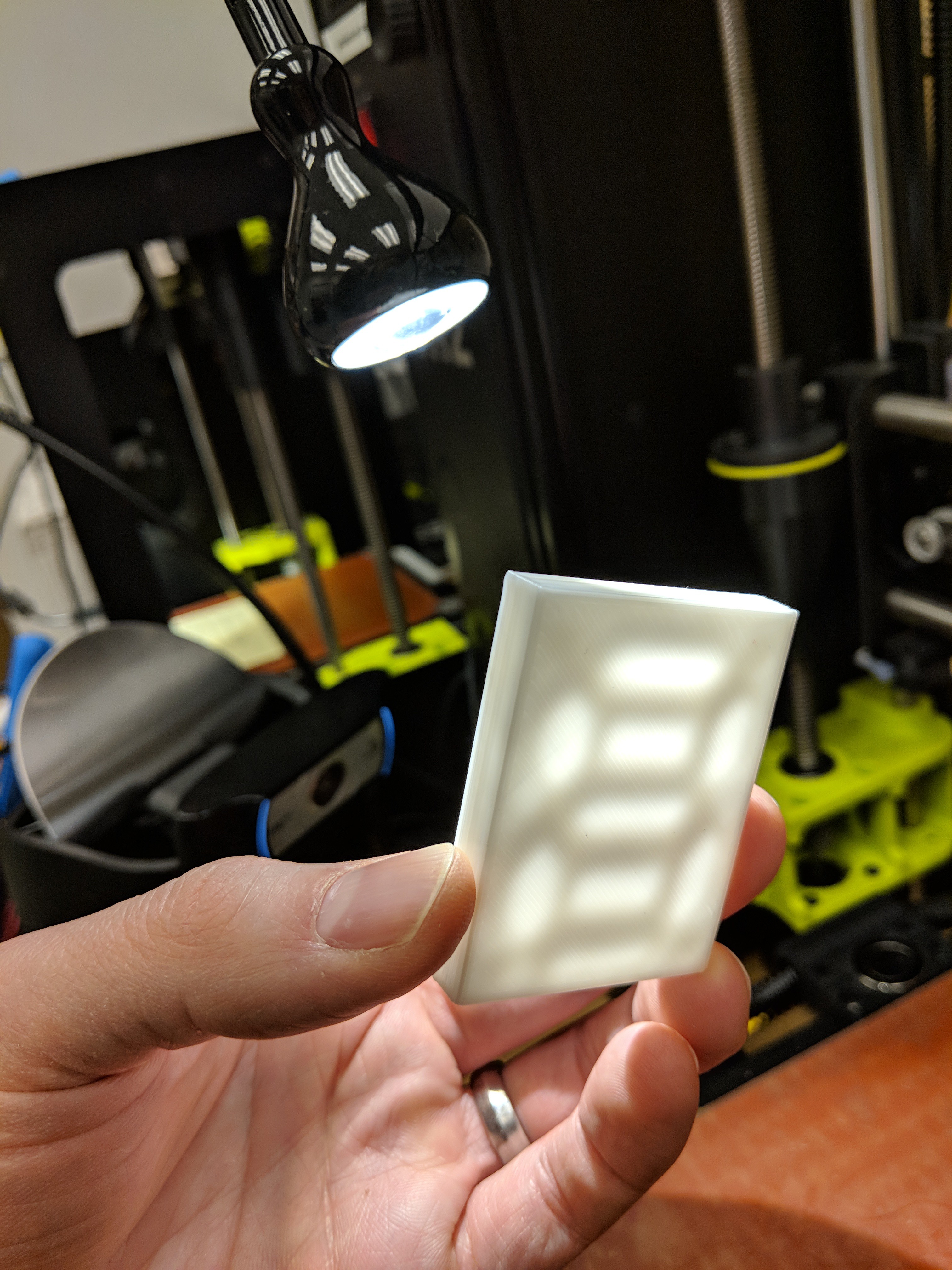
The diffusers will definitely need some more iterating, though, as I think the LEDs wind up too close to the front surface for the light to reach all corners of the "segments" well. I'll say more about the diffusers as they improve, but for now here's a better look at their rev. 1 design:
![]()
![]()
Finally, the current testing setup, with a couple of the digits linked together
![]()
-
Introducing a rotary encoder
01/01/2018 at 23:18 • 0 commentsIn my final NeoPixel clock build, I'm planning to have a knob for easy adjustment of the time, and possibly other settings. A rotary encoder works great for this, and this one also has a push button switch, giving us a few inputs in one package.
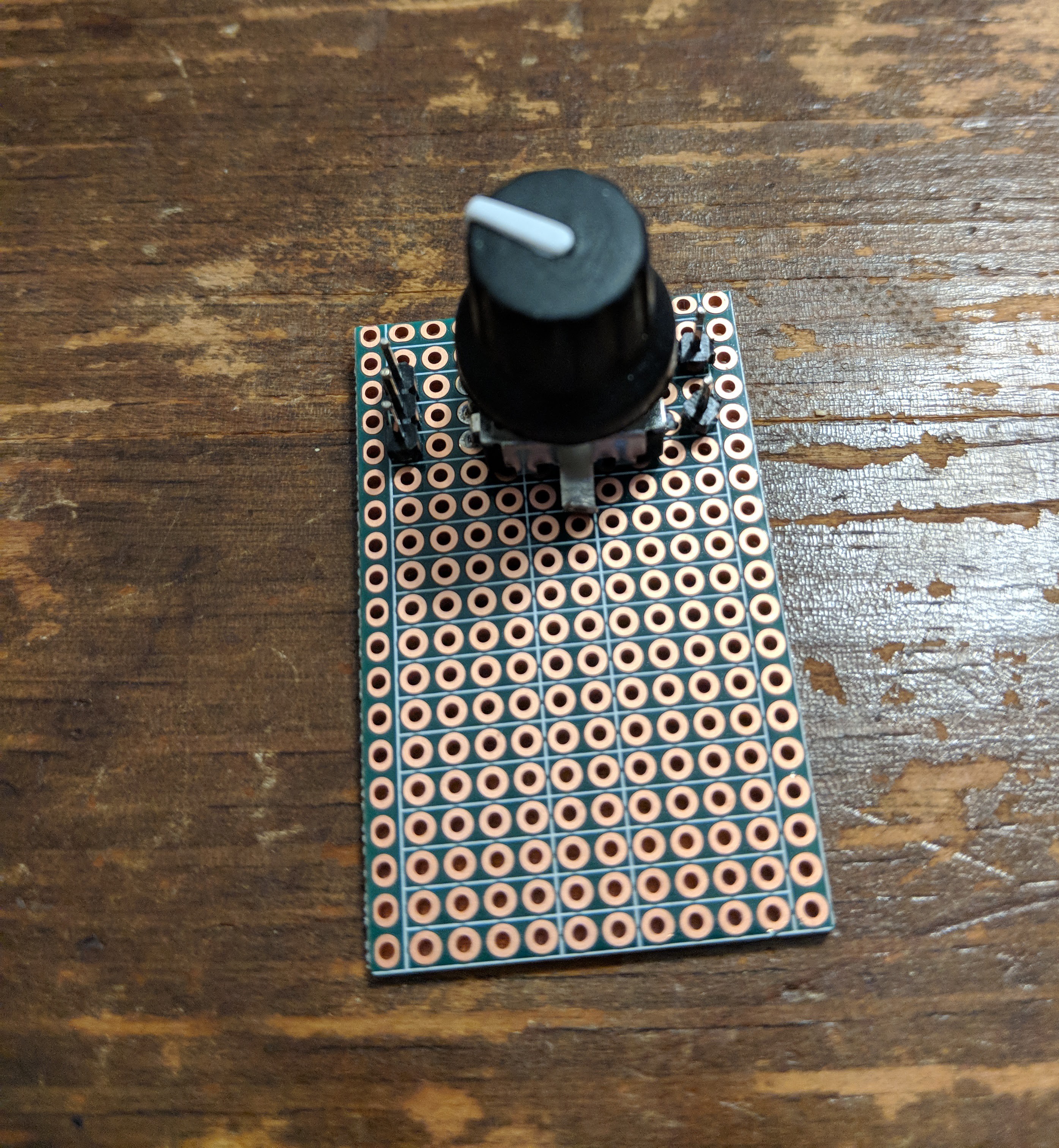
While the rotary encoder has breadboard-friendly pin spacing, I found that it didn't reliably stay seated in my breadboard. I think the wide, flat pin shape is to blame for that. So, to make it a bit easier to work with, I snapped off a bit of proto board (the kind with breadboard-like connected rows) and broke out the pins.
![]()
I suppose I could have attached the pins the other way around to then make it easier to reinsert into a breadboard, but with the pins up, I can just connect right back to my Arduino instead.
![]()
The code for interpreting the rotary encoder signals was modified from the example code here, and it allows me to detect turns left and right on the knob, as well as handling the push button when you press the knob in.
All of that gets me to a demo where I can use knob button presses to switch between 3 modes:
- digit mode
- color mode
- brightness mode
As you would expect, turning the knob in each of those modes adjusts what digit is displayed, in what color, and how brightly!
-
Waiting for PCBs
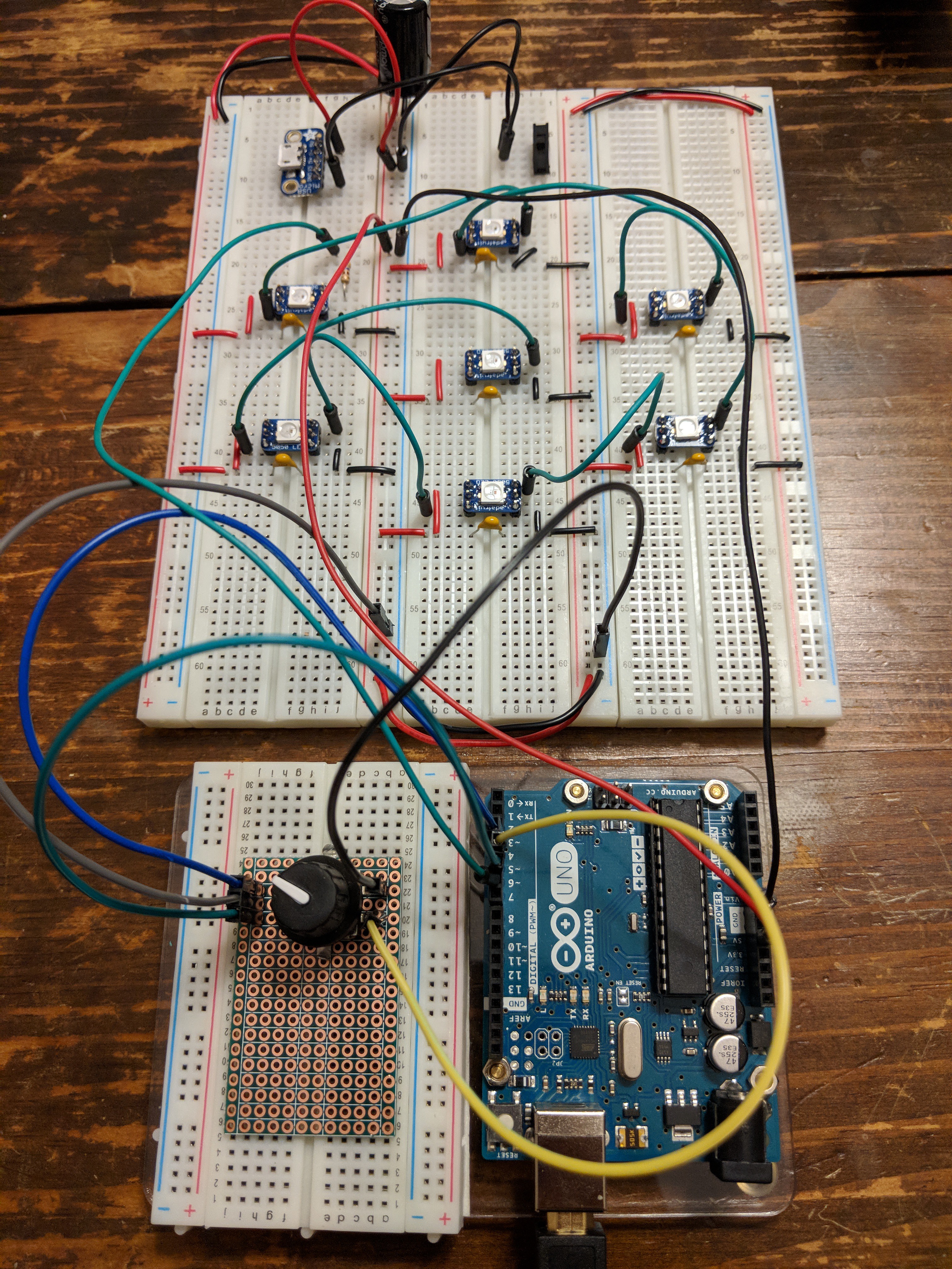
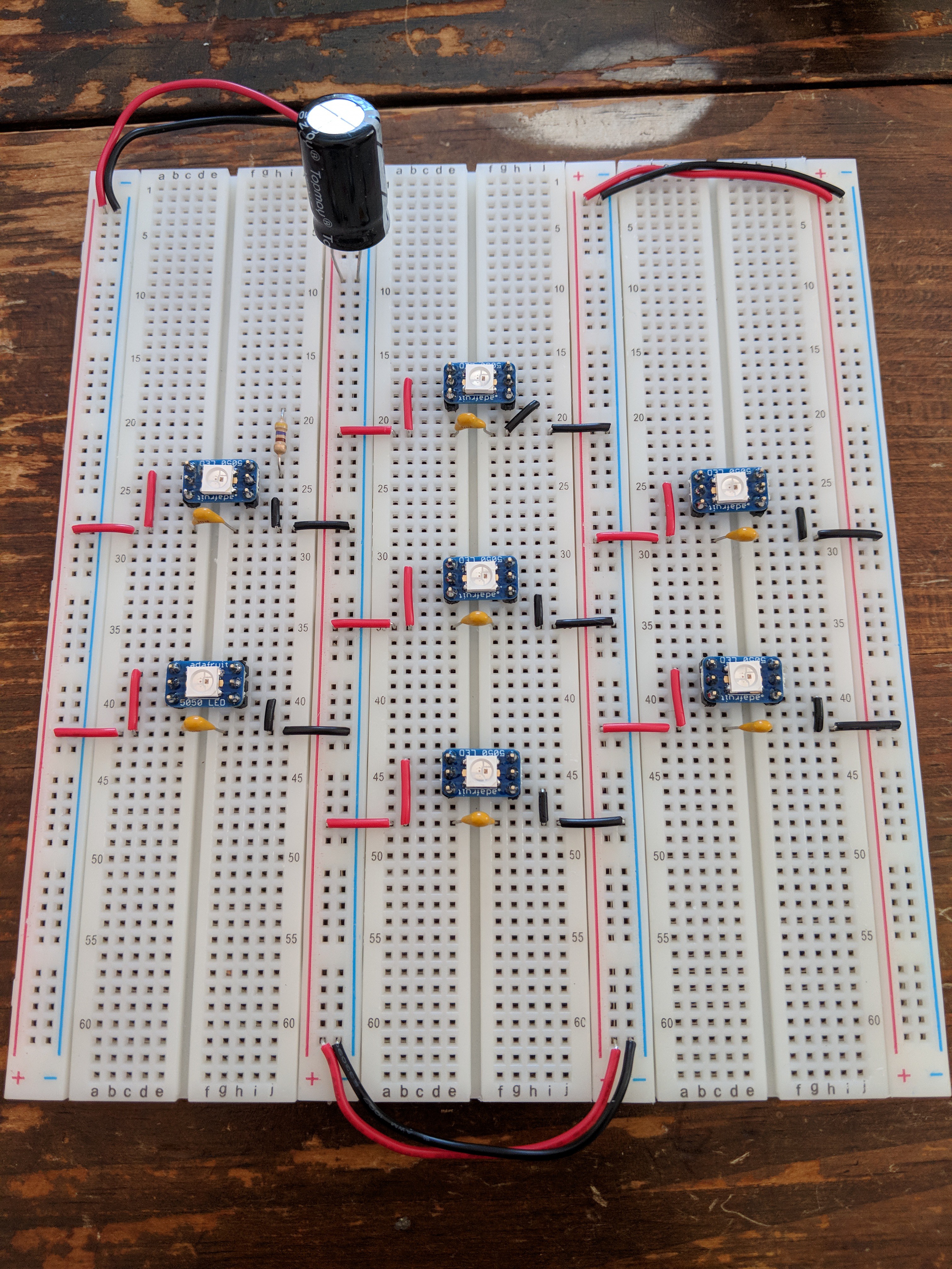
12/31/2017 at 20:31 • 0 commentsWhile I'm waiting for the PCBs to be manufactured and delivered, I've gotten some breadboard-friendly NeoPixels onto some breadboards.
![]()
This configuration should match the PCB design for a single digit, so I can start to write some code against it with the Arduino.
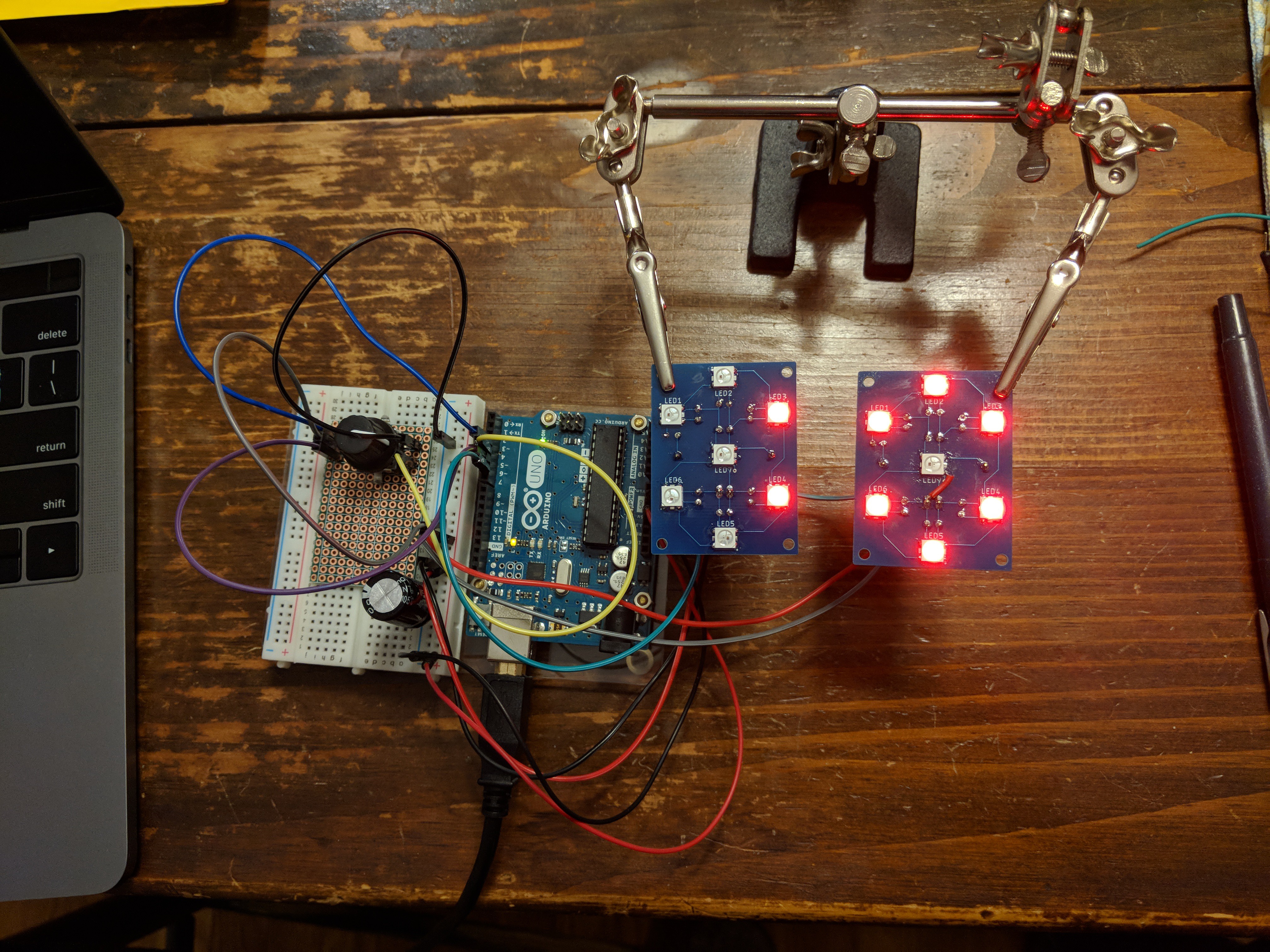
The above is just running a slightly modified version of the strand test sample code, while the below starts to exercise the LEDs as a seven-segment display.
In a short program loop, it displays all of the numbers from 0 to 9 (and blank). It can be a bit tough to visualize without the segment shapes to help, but zero (all segments lit except the center) and eight (all segments lit) are good reference points to follow the sequence from. A slow color cycle is also happening as the digits change.
 Michael Furtak