Close
0%
0%

Erica The Cyber Rhino

An interactive artwork built to help with the goals of rhino conservation and electronics and computer science outreach

Similar projects worth following
Erica is an interactive artwork project built by a team at the University of Southampton in the Electronics and computer science department.
The project aims to help with the goals of rhino conservation and electronics and computer science outreach.
Erica was designed for and has already been deployed as part of Marwell Zoo's go rhinos campaign and is currently being improved so she can go on tour to continue with outreach activities, the first of which being was the big bang fair at the NEC Birmingham

Erica is powered by five raspberry pi computers.

Two of these are used for controlling the eyes and performing computer vision on the video allowing Erica to recognise things like faces and QR codes.

One controls the mechatronics inside the rhino, controlling the state of the LEDs and moving the ears.

The Brain pi controls Erica's reactions and moods which can change based on interactions with Erica and other factors such as the weather, it also has the input for the touch sensors.

The interface pi controls the networking between Erica and the outside world, it is equipped with a additional Ethernet connection and two wireless controllers to provide this connectivity

Two android tablets are also used to provide additional interactivity seeing Erica's current mood for example.

  • Raspbery Pi2's and HATS

    Tyler Ward (Scorpia)02/27/2015 at 17:34 0 comments

    With the 2015 science and engineering family day fast approaching and the release of the new Raspberry Pi 2 Erica is to get a performance boost. With the additional processing power and memory on the new Pis, Erica will be able to do more and react faster. Further updates coming on that soon.

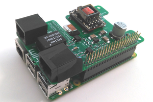
    As the Pi B+ and Pi 2 have a new form factor, the original interfacing electronics built on Humble Pi prototyping boards no longer fit particularly well. To fix this we have created a Pi HAT (Hardware Attached on Top). This contains the electronics to interface between the pi and the rest of the electronics inside Erica. These new boards have been designed with all of Erica's interfaces on a single board, we can then populate the sections of the board that are to be used on each Pi. We are also moving to surface mount components in order to fit all the interfaces into a space a fifth of the size, allowing for all the interfaces to be combined.

    Erica HAT board

    The designs for this board can be found on Erica's GitHub page at https://github.com/EricaTheRhino/PI_HAT_BOARD

  • Erica Plinth Upgrade

    Tyler Ward (Scorpia)04/08/2014 at 13:55 0 comments

    As a part of taking Erica to the big bang her plinth needed improving. The original version had a single captive mains cable to provide Erica with power. Although this was fine when Erica was in the Marlands we have since discovered several issues with this solution, as the cable was captive it was easily damaged when moving Erica around, in addition to this disconnecting Erica from the plinth for maintenance or transport was a difficult task.

    As well as power we wanted to connect other wired devices to Erica such as external speakers or displays. The difficult challenge when doing this is to ensure the plinth is still robust enough that it can survive being based around either in transport or things bashing into the plinth. In addition we wanted to make it easier to disconnect Erica from the plinth, this was especially important now that we where adding additional cables.

    In order to do this we used robust versions of standard data connections, these are commonly used in theatrical or industrial situations. These connectors are usually available in a Neutrik D format housing which can fit into a range of different mounts , we chose to use standard wall plate sized mounts which we screwed onto the plinth. we had put a 4 slot plate under each foot and an 8 way for data and a 4 way for power on the back of the plinth.

    underside of the plinth

    data connections

    DSC_0273_small

    power connections

    For the power connections we used Powercon connectors, as these are locking connectors it means that Erica wont loose power if someone pulls on the cable. as well as linking the back plate to the foot plate we placed an additional out connector on the rear of the plinth to allow an extension lead to be plugged in to provide power for additional devices.

    For the data plate we had a mixture of data types to deal with. For the audio we used 1/4″ unbalanced stereo connections under Erica’s foot and on the rear of the plinth. These where additionally broken out to balanced XLR connectors for direct connection to large speakers.

    For the Ethernet connections we used Ethercon connectors which as well as accepting standard Ethernet cables can also accept reinforced versions that protect the cable end by placing the connector inside a metal surround which can be released with the detach button rather than the usual locking tab. we did a similar technique for the usb and HDMI connections.

    DSC_0260_small

    Ethercon connectors under Erica’s foot

    P1050324_small

    Plinth data connection pannel

  • Erica's New Led System

    Tyler Ward (Scorpia)03/06/2014 at 19:35 0 comments

    Erica’s original system was based around the TLC5940 LED driver chip which was controlled directly by one of the raspberry pis in Erica with an ATtiny45 on the pi daughter board to provide the clock signals.

    Erica old LED setup

    Erica old LED setup

    For anyone who saw Erica in person you will have noted that the LEDs were not always working. Although we haven’t been able to work out the exact cause of the issue we believe it may be due to the chips either overheating (ambient temperatures inside Erica got up to 58C when in the Marlands), or due to large voltages being inducted onto the signal wires linking the drivers.

    To resolve these issues we have created a new LED controller design for Erica. The following are the major improvements over the previous version:

    • As we wanted to avoid replacing or altering the leds we had already installed the new controller is designed to connect up to the connectors on the existing LEDs.
    • The new board uses the same driver chip (TLC5940) as the previous version but is instead controlled by an atmega168 (used on some arduinos) located next to the led driver.
    • In order to improve the signalling between the boards the new design uses the DMX512 protocol, this is often used in event or architectural lighting setups
    • Cat5 cables will be used to connect the boards together as they are easily available and easier to work with than the original ribbon cable connections
    • Internal debugging LEDs to help with diagnosing issues we may encounter.
    • Socketed chips to allow replacement if things go wrong

    Below you can see the new controller design being tested. The controller itself is on the white breadboard, the blue breadboard is the transmitter that will put on the mech pi daughter-board. The cat5 cable connecting the two boards for this test is over 30m long so it shouldn’t have any trouble with the distances inside Erica

    Erica new LED controler test

    Erica new LED controler test

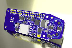
    Rather than build these controllers on strip-board we have designed a custom PCB (Printed Circuit Board)

    Design For Erica's new LED controler

    Design For Erica’s new LED controler

View all 3 project logs

Enjoy this project?

Share

Discussions

Similar Projects

Does this project spark your interest?

Become a member to follow this project and never miss any updates