Close
0%
0%

RTL-SDR With Upconverter and Case

The Junk Box SDR: a simple project to illustrate how it is possible to mount and mod an RTL-SDR and upconverter into a case.

Similar projects worth following
I got my hands on an RTL-SDR a couple of years ago, and was thrilled at the amazing utility of these little devices. I was also bummed at how much interference they picked up.

Here's my simple, ugly, junk box solution.

I got my hands on an RTL-SDR a couple of years ago, and was thrilled at the amazing utility of these little devices. A simple $20 device and some free software (along with my desktop computer) gave me some of the functionality of much, much more expensive equipment such as general coverage receivers and spectrum analyzers. As an amateur radio (aka ham) enthusiast, I immediately saw any number of ways that these devices could help me out around the shack. After adding a Ham-It-Up upconverter, I had the ability to observe signals from DC to 1.7 GHz. Not bad for a total investment of $65.

However, I ran into the almost inevitable problem that almost everyone who has used these devices runs into: RFI. Most receivers have filters in place to limit out-of-band interference. An RTL-SDR has no filtering, it is wide open and picks up EVERYTHING.

Fortunately, this problem has a very simple solution: shielding. My specific solution comes out of my junque collection: a nice extruded steel case that used to be the home of an industrial thermometer.

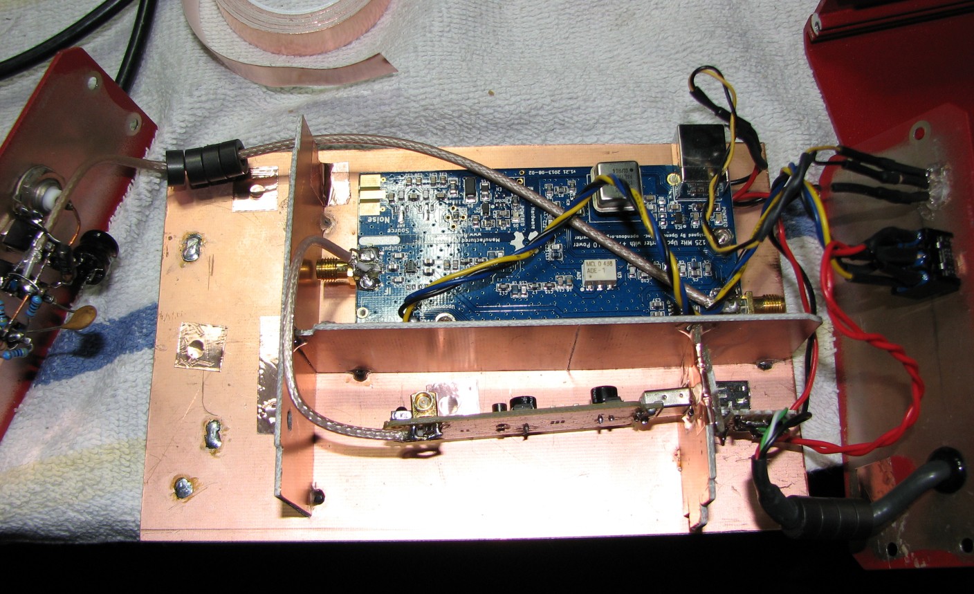
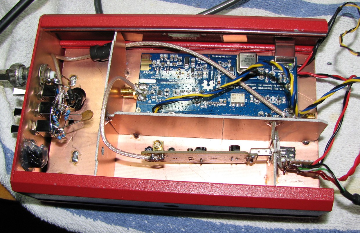
Inside of that case I put some pieces of copper-clad fiberglass in place to support, separate, and shield both the RTL-SDR and the upconverter. I then soldered in some coax to connect the devices to the outside world and each other, added a switch to allow me to switch between modes (upconverter, bypass, and off), and attached a high quality shielded USB cable for data and power. The Junk Box SDR was born.

I also needed something to counter the strong signal coming in from an AM radio station a couple of miles down the road. I decided to add a simple RC filter made of a 100pf cap and a 330 ohm resistor. In theory, this should amount to a 5 MHz high-pass filter. In reality, it does a modest job of reducing interference while still allowing me to listen to the 160 and 80 meter ham bands (1.8 and 3.5 MHz respectively).

Update 11-21-14: The Junk Box SDR has been rebuilt, see project logs below. This is still an ongoing project, as there are still a few ideas I wish to try out with it.

  • 1 × NooElec Ham-It-Up Upconverter Source: NooElec.com
  • 1 × RTL-SDR, RTL2832 + R820T Chipset Source: Ebay
  • 1 × Extruded Steel Project Box Source: Junk Box
  • 1 × Copper Clad Fiberglass Source: Amazon.com
  • 1 × Belden USB Cable Source: Wal-Mart

View all 21 components

  • It's Alive!!!

    DainBramage05/09/2015 at 21:31 0 comments

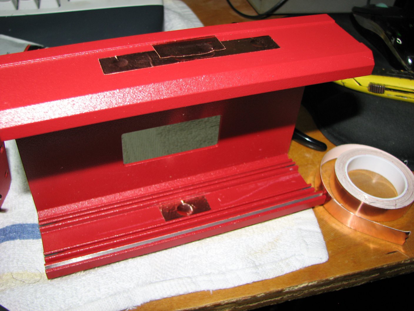
    I thought for sure that my Ham-It-Up had perished from mishandling, ESD, or just plain bad luck. Fortunately, I was wrong. After a bit of testing confirmed that the upconverter was still functional, I got to work patching up the holes in the case with some copper tape and putting the thing back together.

    And a bit more on the chassis:

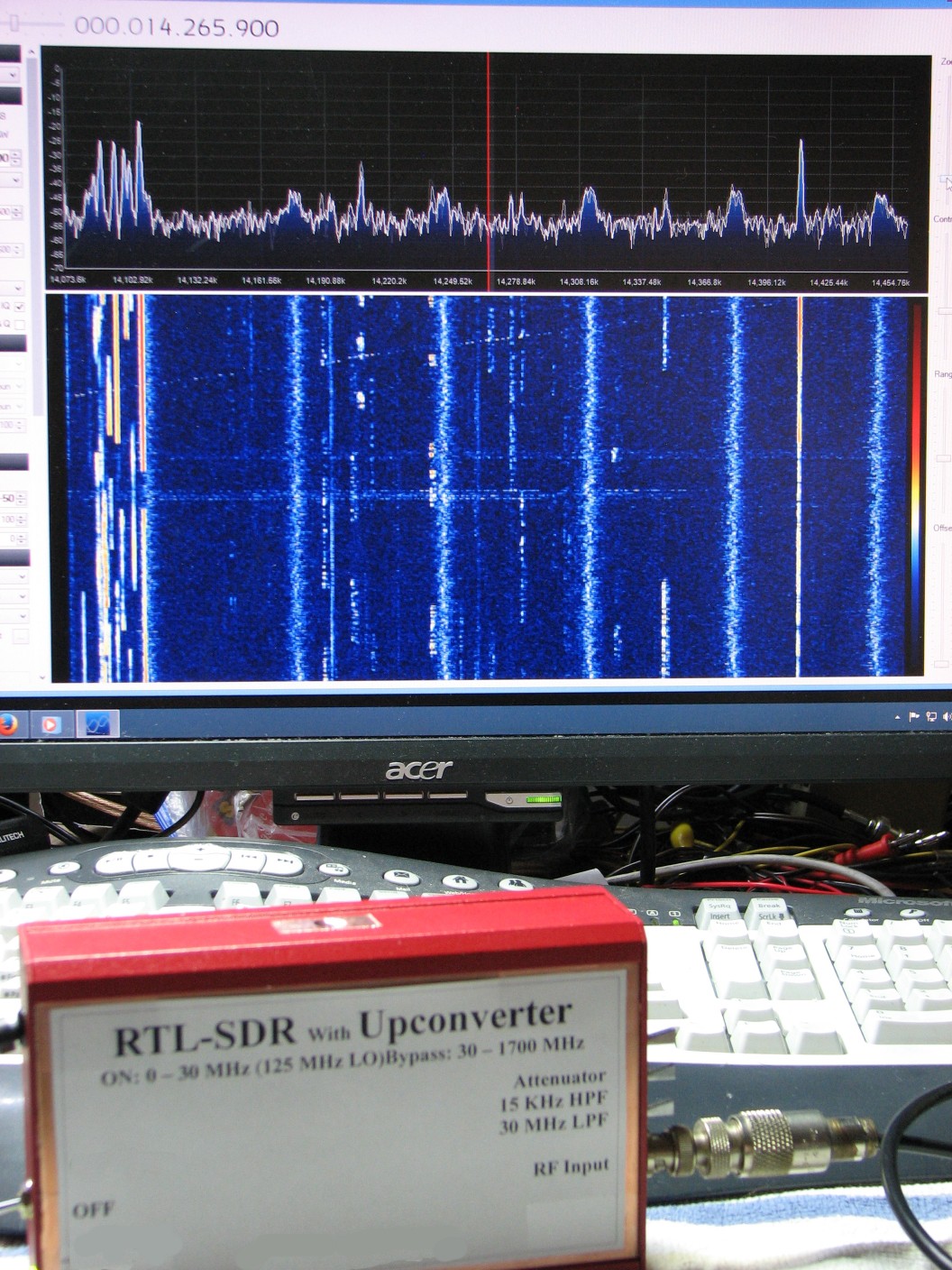
    And we have a working unit again, here listening in on the 20 meter ham band:

    On the right side of the unit are the switches for the 3 filters, which are in series, unfortunately. Someday I will replace the switches with DPDT ones so I can wire them up individually. For now, however, I'm just glad that the thing is working.

    Sort of...

    After working on writing this log for a bit, I found that the thing started randomly losing communications with the computer. The SDR# waterfall would freeze, and I had to cycle the SDR's power to fix the problem, only to have it crop up again a few minutes later. It even froze up during For Whom the Bell Tolls! Seriously, during Metallica's best song? It could just be a loose connection, or it could mean that I need to replace the SDR board. I hope it's the former. Even though RTL-SDRs are cheap, and I do have a couple more lying around I could shove in, I'd rather not start going through them.

    Another ugly fact is that despite all of the work put into isolating the RTL-SDR and upconverter, and all the effort put into shielding them, their performance is not significantly different from what I saw when both devices were completely unshielded. If I am to be honest here, I recommend only putting minimal effort into shielding your own RTL-SDR setups. It just doesn't seem to do much for them, unless you are battling a strong local source of RFI. Even then, it will still come in through the antenna. Switchable filters can help there, but I find that I only use the filters to differentiate between external signals and internal RFI, as when both filters are in and the attenuator is on, the thing is essentially rendered deaf.

    All this effort, and I ended up with what it basically just a convenient carrying case for my RTL-SDR. Oh, well. I learned a lot from it. Hopefully you can as well.

  • Still on Hold

    DainBramage04/29/2015 at 15:50 0 comments

    This project is still on hold while I work on other things that include, in no particular order: organizing my parts supply, organizing my bench, re-working my 12v power solutions (for ham radio), helping a friend get started with electronics, writing a monthly column, and a hundred other things.

    I will get back to this project in time, though I am still waiting for my supply of magic blue smoke to arrive. I may need to contact the seller and find out why it hasn't arrived yet.

  • Watch This Space...

    DainBramage03/09/2015 at 05:10 0 comments

    I've purchased some parts for the Junk-Box SDR, now I just need to spend some time working on the thing. I'm a little worried that I might have damaged the Ham-It-Up at some point, so step one will be to test the upconverter. If it does turn out that I've somehow killed the thing, I don't know what I will do if that's the case. I just hope I'm wrong about this.

  • More to Come

    DainBramage01/30/2015 at 19:38 0 comments

    I haven't forgotten this or shelved it. I've spent the last few weeks thinking about this and I think I've come up with a solution. I just need to get the parts to make it match what's in my head. What parts? A couple of DPDT toggle switches, a 5v relay or two, and a liter of magic blue smoke.

  • One Step Forward, Two Steps Back

    DainBramage01/04/2015 at 23:16 0 comments

    It's funny how no matter how much effort you put into doing something carefully, you will always end up being surprised by how badly it can go wrong.

    I decided that I should remove the new power supply circuit that I had added to the Junkbox SDR when I determined that the vast majority of the RFI I was trying to battle was actually internal to the device. There was also the slight issue of bricking the RTL-SDR when I plugged the data lines into the computer without first turning the power on. Fortunately, the module came back to life after a while. I do have a couple of spares, but I didn't want to be burning them up all of the time, especially not for such a stupid reason.

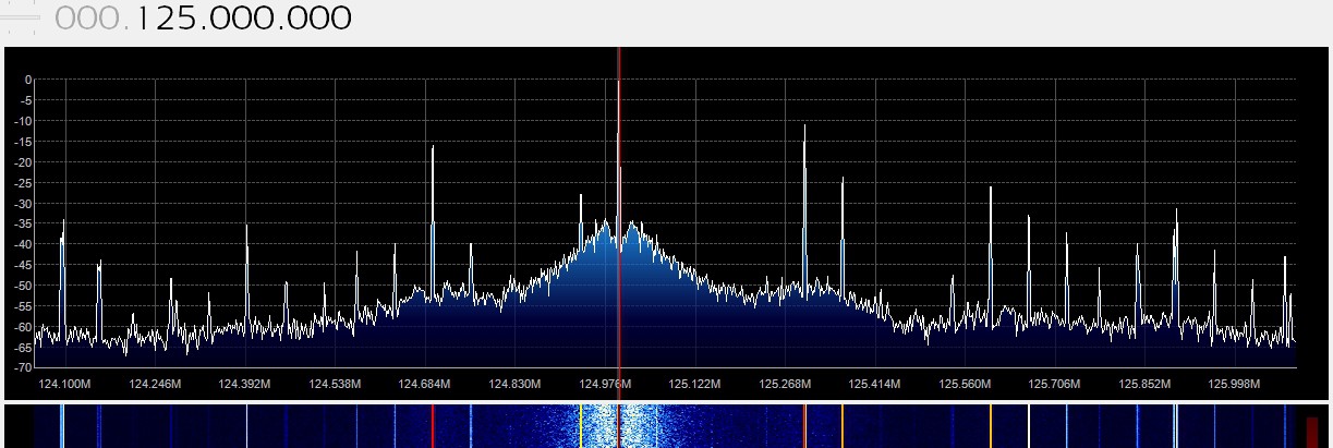
    Here is an example of the RFI seen that is internal:

    This is with a 50Ω terminator across the input. This is actually the 125 MHz local oscillator from the Ham-It-Up upconverter board, which is still active despite the fact that the unit is in bypass mode. This same pattern shows up every 125 MHz up as far as 1.25 GHz. I may have to re-think the whole project. At the very least I need to figure out a way to switch the upconverter completely out of the circuit and power it off when in bypass mode (using the RTL-SDR only).

    One improvement I managed was to make the filters actually function by actually soldering them up the way I had originally intended, instead of the hurried miswiring I had done before. It looks like total crap, but at least it works... Sort of. The filters can only be switched on in sequence, rather than individually. I figured out a circuit that will fix this problem, but I'll need to pick up some DPDT switches to replace the SPDT ones that are there now.

    The work progresses, slowly. My intention is that this project end up being a simple to use general coverage receiver. I'm heading in the right direction, but the title of this log entry says it all.

    Work in progress...

  • Warts and All

    DainBramage11/16/2014 at 01:09 0 comments

    Well, I thought I might actually have the project done by now. After all, it is all buttoned back up and fully functional. ...Almost.

    After spending many days designing, tearing apart, reconfiguring, thinking about, and generally messing this project royally up, I finally put the thing back together and turned it on. That was when I realized all of the mistakes I had made.

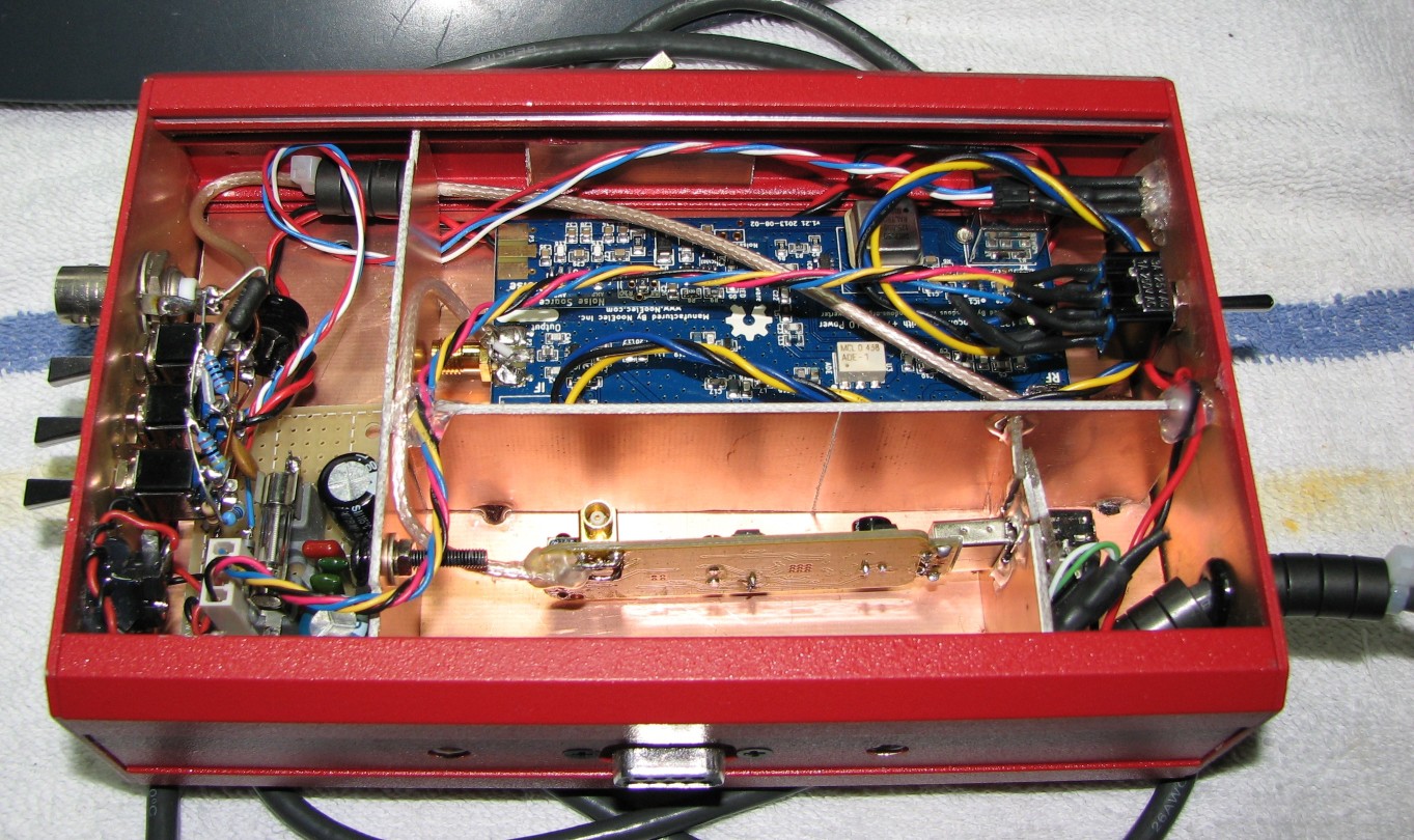
    First off, a recap. I had intended to make a number of changes to the original Junk Box SDR, so much so that I almost considered calling it the Junk Box SDR 2.0. However, that sounded extremely lame, considering that the main electronics (the SDR and upconverter) were unchanged. The changes that were actually made were: better shielding by filling in some of the holes, completely isolating the internal power from USB by adding a 12v to 5v DC-DC converter (a simple 7805 with plenty of smoothing caps) and drawing power from the Astron RS-35M that I use to power the rest of my ham radio gear, isolating internal components from each other, adding switchable filters and an attenuator, adding a bi-color LED to indicate which mode the SDR was in (upconverter active or bypassed), and generally cleaning things up and doing a nicer job of things.

    Here are my more obvious mistakes: The filter circuit I designed never stood a chance of working due to an oversight so obvious I am too embarrassed to share it with you. The photo I posted is probably sharp enough for you to figure it out. Total facepalm moment. Speaking of facepalm moments, I had a similar feeling when I realized why the bi-color LED showed up as orange instead of either red or green. Yup, I'm feeling pretty stupid right about now.

    The one thing I'm not blaming myself for is the discovery that the SDR and upconverter are actually generating much of the noise I was hoping to be able to get rid of with this project. That was an unexpected blow, but one I would not have been able to discover without going through all of this trouble.

    Here it is, warts and all (minus the top cover):

    Now that I've made a complete fool of myself in this somewhat public forum, I can start to work on coming up with fixes for the various problems I have created. However, I am feeling a bit burnt out today, so the Junk Box SDR will go up on the shelf in front of me until I feel like cracking into it again. I hope those following this project will be patient with me. I'm also open to suggestions, provided they can be achieved with little to no monetary expenditure.

  • The Junk Box SDR is Coming Along

    DainBramage11/12/2014 at 16:39 0 comments

    I've been making some progress in re-building what I am now calling the Junk Box SDR. As I mentioned the other day, I have built a small 5v power supply. I have since added another zener diode on the 5v side to protect that side of the supply (from what I don't know, but it's there nonetheless). I have also started wiring up the connections to the power supply board.

    I'm trying to reduce USB noise as much as possible, so in addition to adding a number of ferrite beads to the USB cable, I am bringing it into its own small compartment. The two power wires and the cable's shield are dead-ended and covered with heat-shrink, and the two data wires are connected to a female USB connector that will be supporting the actual SDR dongle. I've also brought power wires from the power supply board into this small compartment, so that the SDR dongle can now be unplugged and removed more easily, should it need replacement (I'd still have to unsolder the antenna lead).

    I've finalized the filtering scheme: I have one high-pass filter with a cutoff frequency of 1.5 MHz to reduce interference from local AM radio stations. I have a low-pass filter with a cutoff frequency of 30 MHz to reduce front-end overload from the many local FM radio stations. Lastly I have a 50dB pi attenuator. All of these are switchable, so they can be used as needed. The only issue I have is that there is no easy way to make these work from the front panel. Actually, the Junk Box SDR doesn't really have a front panel. This is somewhat annoying to me, and if I ever do one of these again I will design it from the ground up so that all of the controls are on one side and all of the wiring is on the opposite side. It's a bit messy as it is now, but it is a junk box project, so I've had to make do with what I could get my hands on. With the exception of the SDR, the upconverter, and the switches, everything in the Junk Box SDR actually came from my junk box, hence the name.

    More photos to come.

  • Progress

    DainBramage11/09/2014 at 02:51 0 comments

    Things are rolling along, slowly.

    I've mostly been doing planning and testing, which involves a lot of running up against my own limitations.

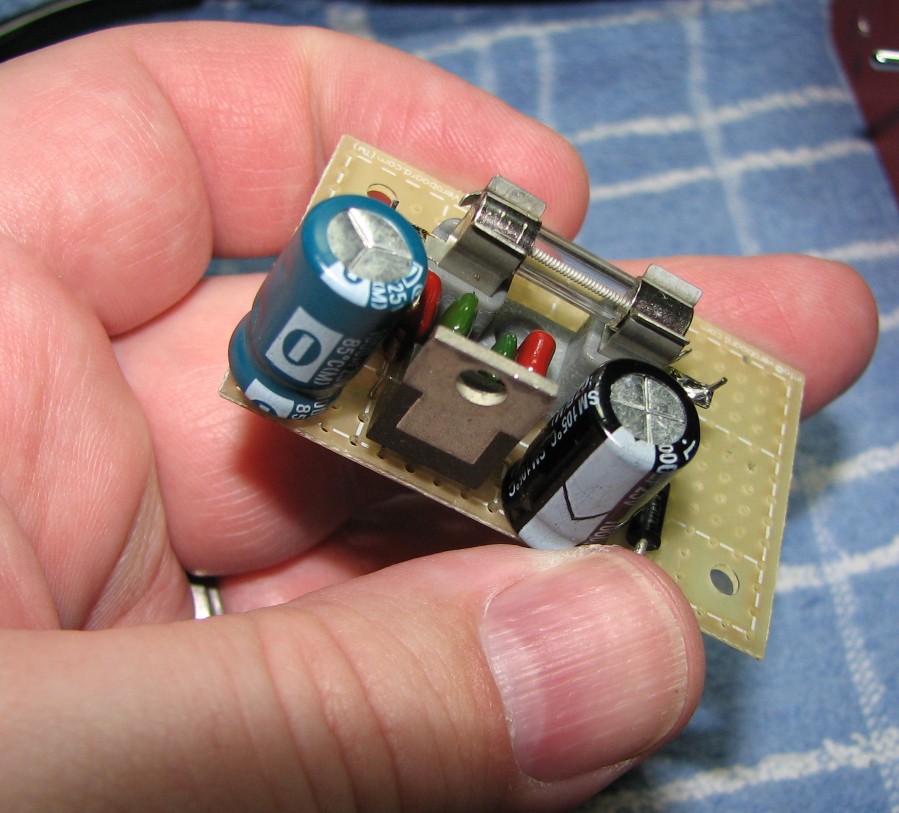
    I have decided to isolate the RTL-SDR and upconverter boards from the computer (read: noise source) as much as possible. I don't have access to a USB isolator (yet), so I've decided to give the box (I need to come up with a name for this thing) it's own 5v power supply based on an LM7805 linear regulator. Power will come from the same Astron RS-35M that powers all of my other ham radio gear. I've already built the 5v supply board, and tested it on my Rigol scope. It shows less than 5 millivolts of ripple, so it should work well. I will also be using the case as a heat sink for the 7805, so I should be able to pull between 1 and 1.5 amps without risking damage to the regulator. I've also included a 21 volt zener diode along with a 2 amp fuse, a combination which will provide over-voltage, over-current, and reverse polarity protection.

    I will include a circuit diagram later, but for now here is a closeup of my fat fingers for your viewing pleasure. Oh, and the supply board also.

  • Equipment Failure Workaround

    DainBramage11/01/2014 at 15:58 0 comments

    Okay, so the trusty old Singer CSM-1 isn't so trusty, but I did find a workaround that allows it to work perfectly. Almost.

    It's 10 Hz off, but hey, you would be too after 40 years of service.

    I did the first of the measurements last night and was absolutely blown away by the raw sensitivity of the amazing little SDR. Starting at 100 KHz with the upconverter active (so we're looking at it's sensitivity as well), the sensitivity was -62dB. Not a very good start, but we're at a pretty low frequency. Most wide coverage receivers are crap down there anyway. I started testing every 100 KHz, and the sensitivity went up quickly. By the time I got to 1 MHz, it was up to -100dB (up to?). From 3 MHz and up, the sensitivity was at the maximum I could measure with the CSM-1, -110dB. That's as sensitive as my Yaesu FT-857D, which cost an awful lot more than that $20 SDR module!

    At 70 MHz the sensitivity started to drop off, until I realized that I was reaching the limits of the Ham-It-Up upconverter. I switched it out of the circuit and continued on all the way to 550 MHz, the upper limit of my CSM-1 (the SDR measured -110dB at all frequencies). Technically it can go higher using harmonics, but the output amplitude of those harmonics won't be at the calibrated level. Good for frequency testing, but not for precisely measuring sensitivity.

    So, in it's current configuration, this cheap-as-beard-dirt SDR module is very, very sensitive. However, it's still wide open and noisy as anything.

    More testing later, when I start playing around with various filtering circuits and ideas.

  • Equipment Breakdown

    DainBramage10/31/2014 at 14:42 0 comments

    I finally sat down with my RTL-SDR in hand to do some starting measurements before tearing into it. I fired up my trusty old Singer CSM-1 service monitor only to find that it was not putting out a clean tone on frequency, and was generating very strong signals every 4 MHz or so for roughly 20 MHz on either side of the center frequency. Also, the center frequency signal, in addition to being dirty, was also very weak at roughly 10dB above the noise floor (much of that noise was coming from the CSM-1 itself).

    Since the attenuator is passive and the last device in series before the output port, I thought I could at least use those strong signals to do my testing. Then I realized that I have no way of accurately knowing what the baseline amplitude of those signals was, so I can't use them to measure receive sensitivity in the SDR.

    I've spent the last two days tearing into the CSM-1 with a screwdriver in one hand and the service manual in the other, but I have been unable to determine what the problem actually is.

    If anyone has any specific knowledge about this issue, I welcome your feedback. I really would like to have my service monitor working again, as I don't have any other equipment that can stand in for it.

    The rebuild of the RTL-SDR may be on hold for a bit while I try to figure this out.

View all 13 project logs

Enjoy this project?

Share

Discussions

Roger Pience wrote 01/27/2015 at 02:21 point

You are on the right-track with shielding, however eliminating EMI and other RF noise requires an OCD-like dedication.

If I may offer some hints:

1. The double-sided PCB shields need a continious solder bead along all seams. (no chinks in the armour ;> )

2. Add an RF-tight fitting lid to the PCB enclosure

3. All wires and cables must be bypassed through the shield walls. No notches or gaps.

4. Coaxial cables must have RF choke beads to eliminate common-mode currents.

5. A better solution might be to separate the individual modules into their own shielded boxes such as cast aluminium from Bud or other OEM

Good luck;

XP

  Are you sure? yes | no

DainBramage wrote 01/27/2015 at 02:24 point

Hints noted, thank you!

I do have a proper lid, but didn't show it in the photos. I will definitely keep your suggestions in mind the next time I go to work on this project.

  Are you sure? yes | no

Phil C. wrote 02/09/2015 at 17:29 point

Roger, I'm looking at doing one of these as well. I'm also a ham and am good at electronics but a bit weak in RF. What do you mean by "bypassing" wires and cables through the shield walls? Could you please give an example? Many thanks.

  Are you sure? yes | no

kc8rwr wrote 11/24/2014 at 18:20 point
I've had an idea I wanted to play with for quite a while but haven't gotten around to and probably never will. I'd like to add an upconverter to my RTLSDR. Instead of having a manual switch I'd like to tap into the I2C bus on the SDR stick. That way I'm thinking I could modify the RTLSDR driver so that it manages turning the converter on and off as well as translating the frequency. Then the SDR software at the computer would always display the correct frequency and wouldn't even know there was an upconverter involved.

As a simple implementation i'd just send a on/off signal over I2C to a small micro, maybe an Attiny that then controls the power and antenna bypass switches. Another way to do it would be to send the actual requested frequency to the Attiny. That way the Attiny could also control an antenna switch allowing me to use different antennas for different bands. If this became a common hack it could become a standard part of the driver. Since the actual decision about which antenna to use based on frequency would be programmed into the Attiny, not the driver it could still be universal.

My motivation for this is that I would like to put the whole setup in my attic allong with a Raspi or something similar running rtltcp. The receiver would be right there at the antenna(s) with virtually no line loss. Data and power would both be via Ethernet.

  Are you sure? yes | no

kc8rwr wrote 11/24/2014 at 18:20 point
Oh, yeah, I posted all that hoping you will do it. Cheers!

  Are you sure? yes | no

DainBramage wrote 11/24/2014 at 18:54 point
Fantastic ideas! I suspect that a setup like that could be made to work, as the manual bypass switch is actually controlling a pair of electronic switches on the upconverter board. It would be very easy to control those with a µC, I think.
Unfortunately, because of the nature of frequency upconversion, the software being used has to "know" whether or not an upconverter is being used, as the upconverter literally shifts the signal 125 MHz higher in frequency (and I don't think that the RTL-SDR is smart enough to figure that out for itself, but I could be mistaken). For instance, If I want to listen to WSPR signals on 10 meters, I can tune the RTL-SDR directly to 28.1246 MHz with the upconverter bypassed, or I can tune the RTL-SDR to 153.1246 MHz with the upconverter active. Most software that I am familiar with (I use SDR# mostly) allows you to include an offset, so all you need to do is check the offset box and set it to -125 MHz to have the frequency display accurate. Either way has similar results (it's actually better to use the upconverter there as the RTL-SDR loses some sensitivity as it gets close to its frequency limits), but the end-user has to know what's happening in the hardware at the time in order to set to offset. I suppose it might be possible to have a µC set the offset flag in SDR#, but I just don't know.

I might attempt something like this in the future, but I don't know if I possess the skills to pull it off. If you try this out, by all means post it on hackaday.io and send me a link! I'd love to see your implementation.

  Are you sure? yes | no

kc8rwr wrote 12/10/2014 at 15:21 point
" because of the nature of frequency upconversion, the software being used has to "know" whether or not an upconverter is being used"

That's why I was talking about writing support into the driver. The SDR software doesn't "talk" to the rtl stick directly right" It talks to the driver which then talks to the stick. The driver would have to know that for any frequency below about 60Mhz or so it has to add 100 MHz and send a message to the µC via i2C telling it to turn the converter. The SDR software then could be ignorant of this, it would just know what frequency it told the driver to give it thus the display would be correct.

The hardest part, I think would be that it would require modifying the driver. I wouldn't want to have to permanently maintain my own copy of the RTL-SDR driver which only supports my own custom hardware for life. Every time a new version comes out it would be necessary to get it and then merge the upconverter support back in. That would get annoying. The trick i think would be making the implementation generic enough and getting a whole community of people using it so that the upstream driver authors would be motivated to include the patch.

Thinking about this more, maybe it would be possible to make a go-between. Something which would talk to the standard RTL-SDR driver instead of the SDR software talking to it directly. It would manage the turning on/off of the converter and provide an interface for the SDR software that matches what it would see if it were talking to the driver directly only with seemingly built-in HF support. Then there would be less of a maintenance issue. I'm not sure if it would be possible to do that and use the idea of tapping into the stick's I2C bus though...

For Christmas what I want is more time to play with stuff like this!!!!

  Are you sure? yes | no

DainBramage wrote 12/10/2014 at 17:27 point
Unfortunately, rewriting driver software is way above my head. My programming skills are rudimentary at best.
While I would love to see something that can control both the SDR and the upconverter while also dealing with the SDR software, it's not something that I will be tackling myself, at least not any time soon.
Still, I do think it falls well within the realm of possibility, so I encourage anyone with the time and skills to give it a shot.

  Are you sure? yes | no

Michael R Colton wrote 10/17/2014 at 17:49 point
I'd love to see if you have any before and after measurements with this. Nice work! I saw someone using a USB isolator somewhere, that might help further.

  Are you sure? yes | no

DainBramage wrote 10/18/2014 at 01:34 point
I wish I had the foresight to do real measurements before and after, Michael. All I can say is that the amount of times I run across spurious signals has dropped considerably. The signals I am seeing tend to be cleaner, and I can now look at signals below 5 MHz without the local AM station de-sensing the front end.
It was definitely worth the effort of enclosing the devices, but now I wish I had done a nicer job!

  Are you sure? yes | no

DainBramage wrote 10/18/2014 at 01:38 point
Oh, we may also have more in common than just ham licenses. Did you enjoy General Conference?

  Are you sure? yes | no

Michael R Colton wrote 10/18/2014 at 02:47 point
I did, very much. How did you know?

  Are you sure? yes | no

DainBramage wrote 10/18/2014 at 03:01 point
You mentioned serving a mission in your interview, and you live in Utah. It wasn't hard to make the connection. :D
We enjoyed conference here also. I actually managed to stay awake and alert for all sessions, which is quite an achievement for me.

  Are you sure? yes | no

Michael R Colton wrote 10/18/2014 at 06:15 point
Ahh, I forgot about the interview. I know what you mean about staying awake. I did better than usual this time too.

  Are you sure? yes | no

DainBramage wrote 10/18/2014 at 16:50 point
I'm also 2 timezones ahead of you, so the Saturday evening session runs from 8pm
to 10pm. I can tell you from experience what sitting in a chapel full of snoring
men is like. :D

  Are you sure? yes | no

Similar Projects

Does this project spark your interest?

Become a member to follow this project and never miss any updates