Jarrett
-
I'm tired of using words!
04/02/2015 at 16:01 • 0 commentsCNC Day Best Day.
![]()
![]()
![]()
It's a space ship!
![]()
![]()
![]()
![]()
Next steps:
- Properly mount the Piccolo onto the box (my first mounting choice didn't quite work out).
- Cut away a little bit of the pump mounting tab because it interferes with the Piccolo travel.
- Update the Arduino sketch (ugh) to jog the electrode properly to keep it in the conductive region.
- Get money
- Smoke trees
- Wisdom
-
Start Small. Small EDM tank.
02/03/2015 at 17:06 • 0 commentsOther than wanting to spend very little money on this project, the scope of it is huge enough that I've been trying to use as many prebuilt components as possible.
If I have the majority of the project build with discrete, modular components, then I can start drilling down and replace the weakest links, one at a time.
Because the CNC portion is horribly complicated, and itself comprised of several parts (drive electronics, mechanical movements, control software, firmware), several weeks ago I made the decision to use a low-cost CNC platform. I mean "platform" in the sense that it's designed as a starting point to hack, redesign, and improve.
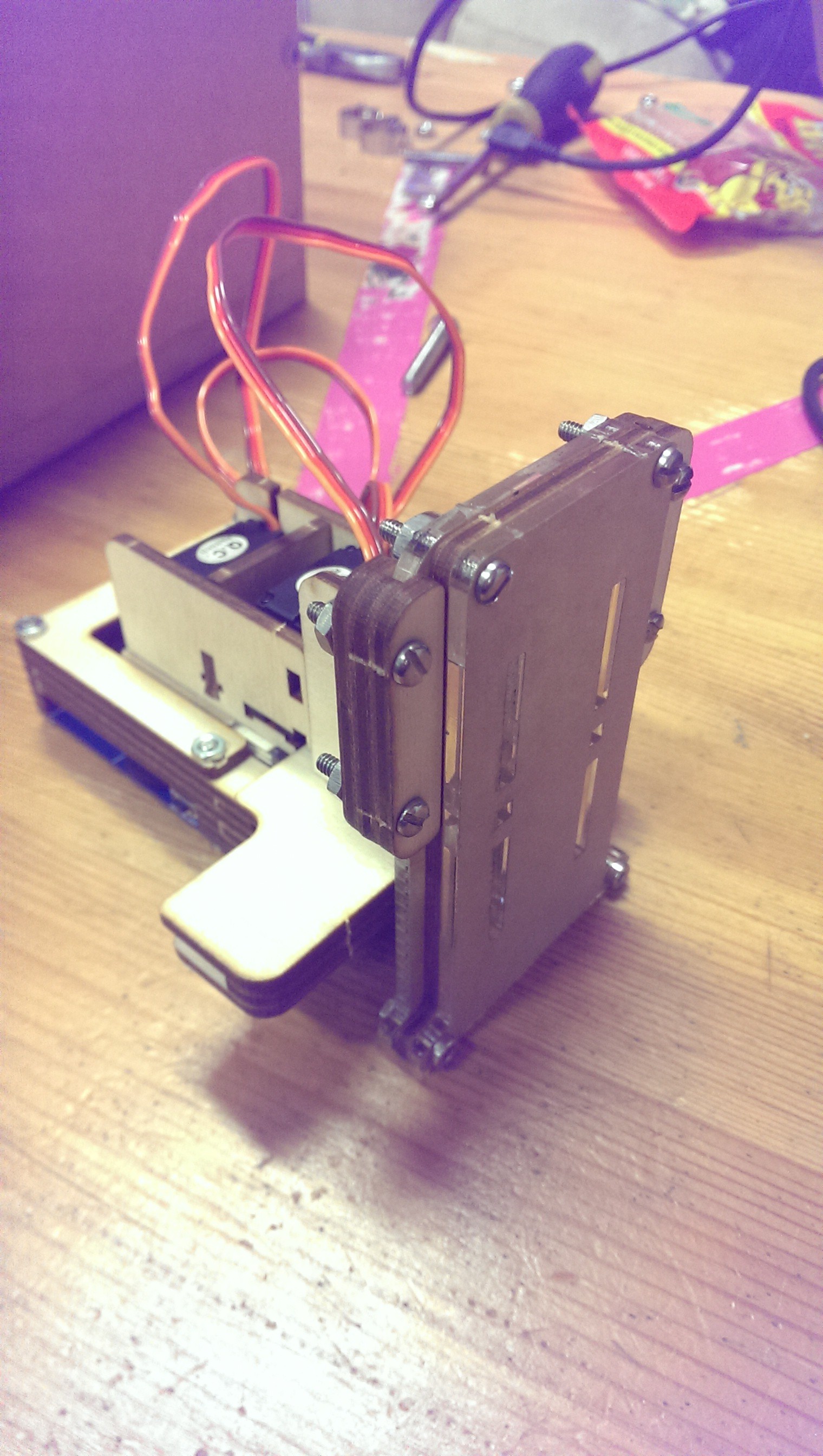
It's called the Piccolo:
![]()
It uses three (TINY!) servo motors, a bunch of laser cut gears and mounting plates, and some Processing-based software. Everything is open-source, and I don't think they even sell any of the components themselves. They provide all of the files and expect people to make it on their own, which is kinda cool.
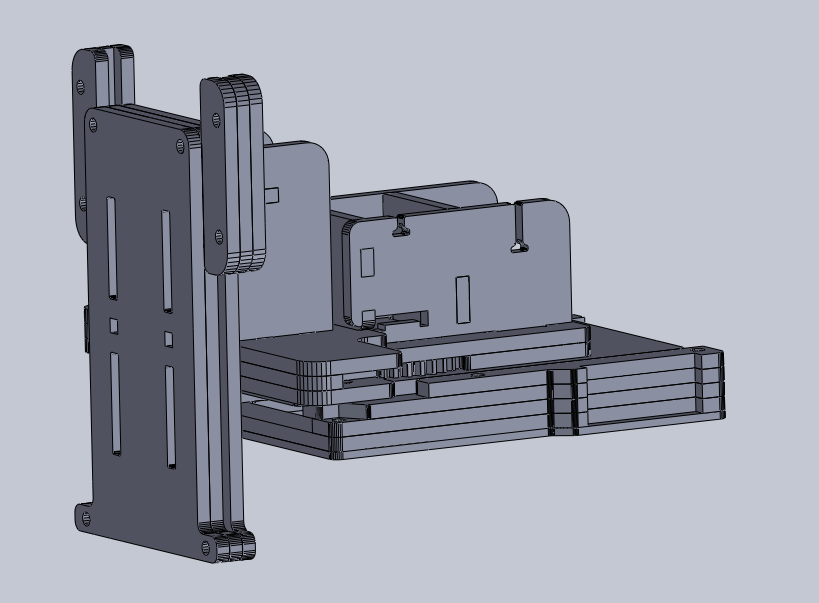
One thing I couldn't find on their site anywhere was the work area. I needed dimensions of all of the parts to mount and design around this anyway, so a couple hours with their laser cutter files produced this:
![]()
Turns out all axis have a range of about 2.5 inches. That's really tiny for a CNC platform, but definitely usable for making PCBs. At first, anyway. That double-ensures that this portion will eventually be replaced, probably with a CNC system of my own design. That will be fun, I am looking forward to it.
One note for future-self:
There is a decent chance that the sparking from my electrodes will cause enough interference to mess with my servos. If they get really jittery during a burn, I know exactly what is happening, and a redesign will happen sooner rather than later.
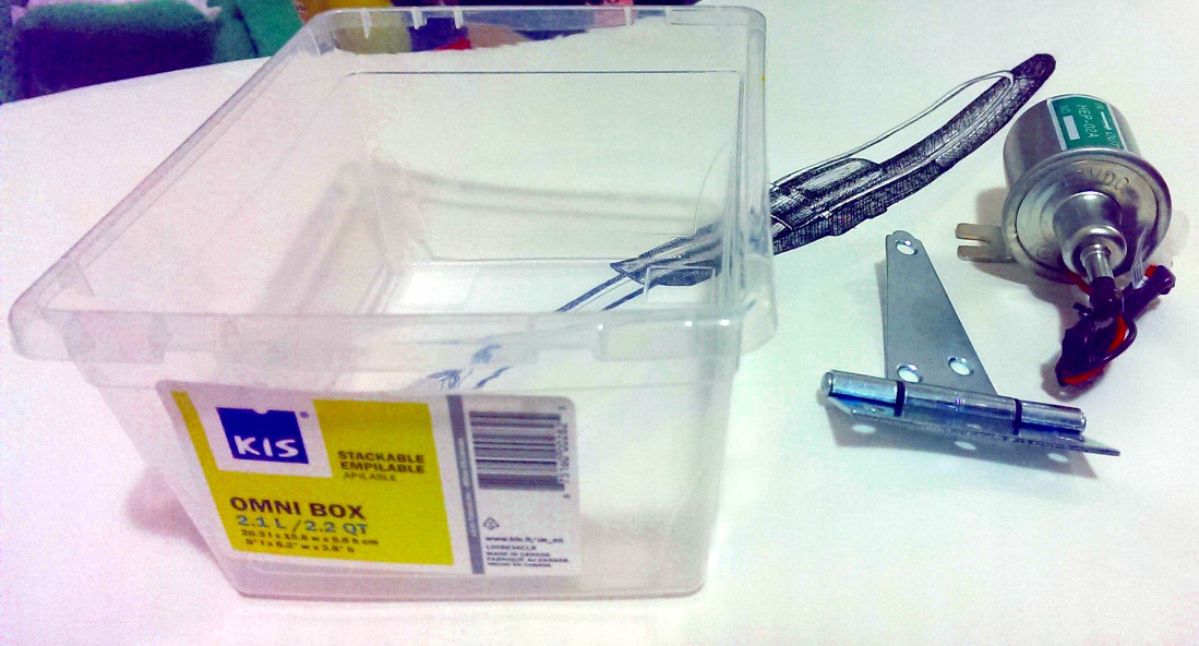
Working with the above files, I gathered together some more materials:
![]()
A 12V oil pump($12) for the EDM fluid (more on this in a future post), a standard heavy duty door hinge($3), and a small plastic tank($0.89). The tank is a lot smaller in person than it looks.
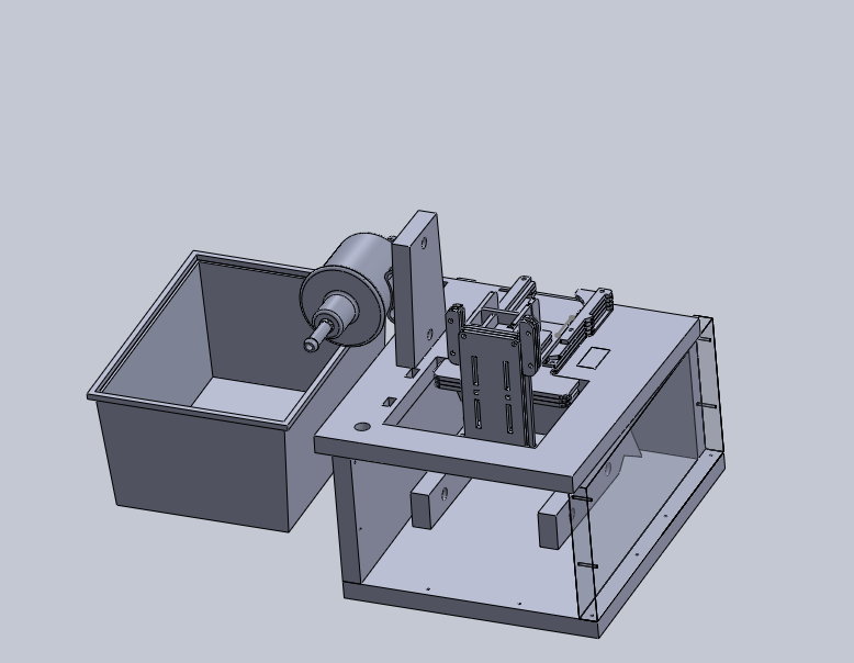
Putting it all together:
![]()
That's a reasonably accurate mode of the tank on the left.
There's also models of the Piccolo and the fuel pump that you can see there.
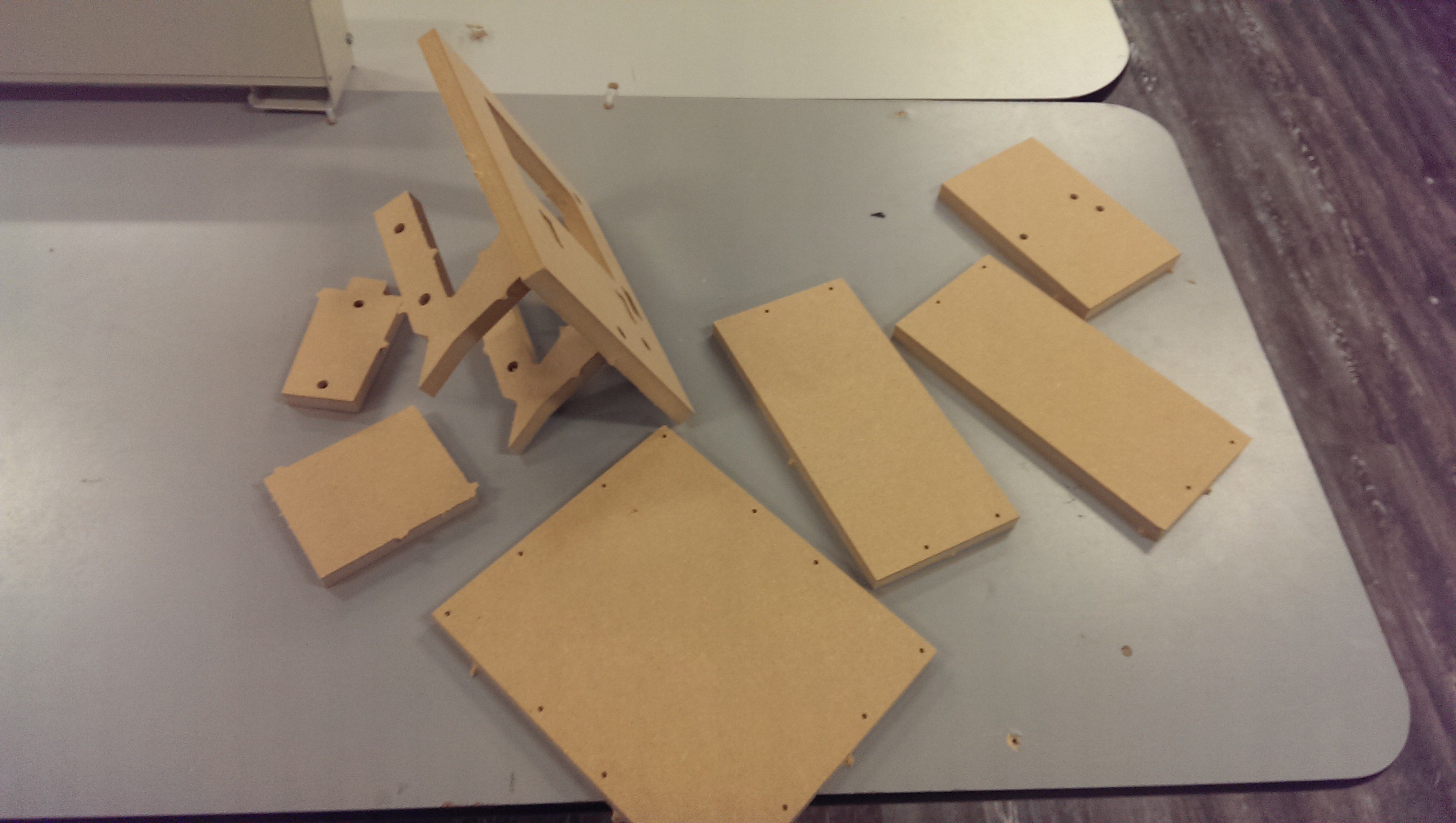
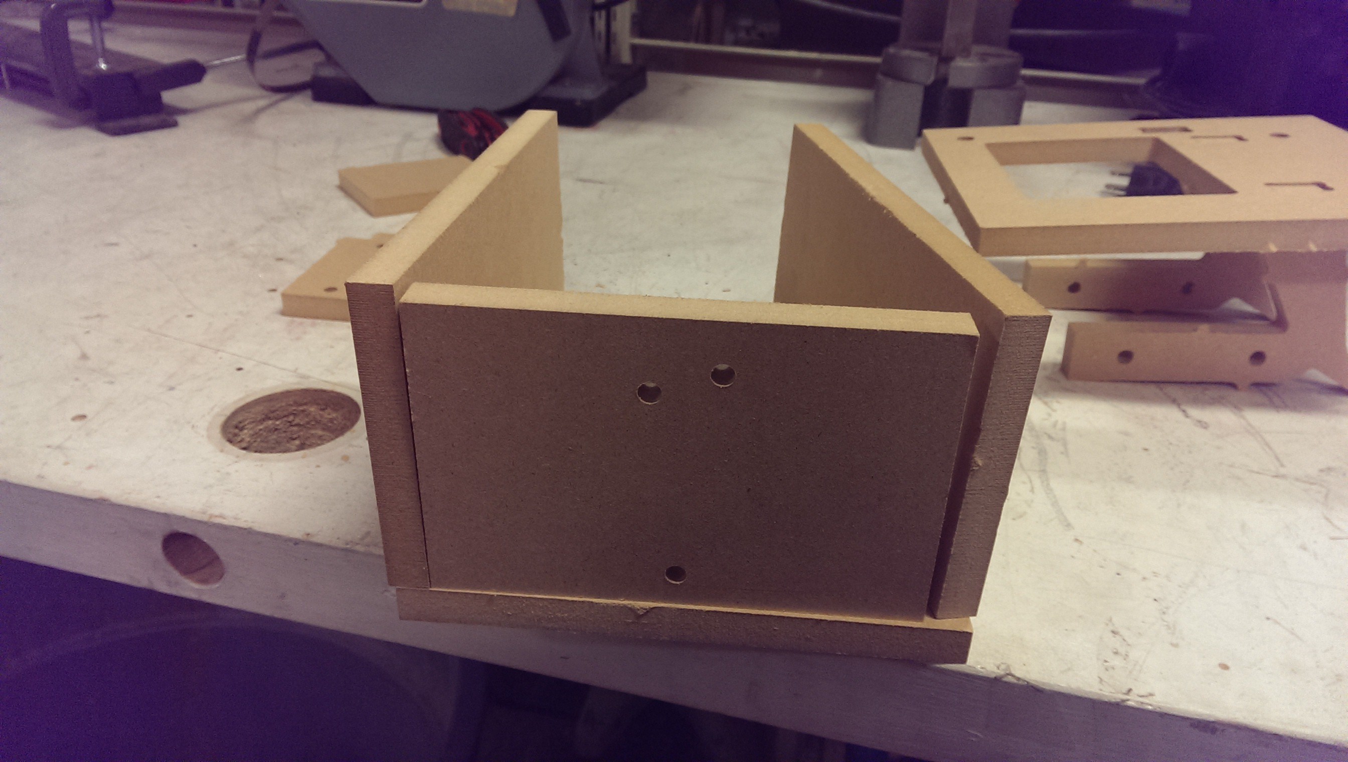
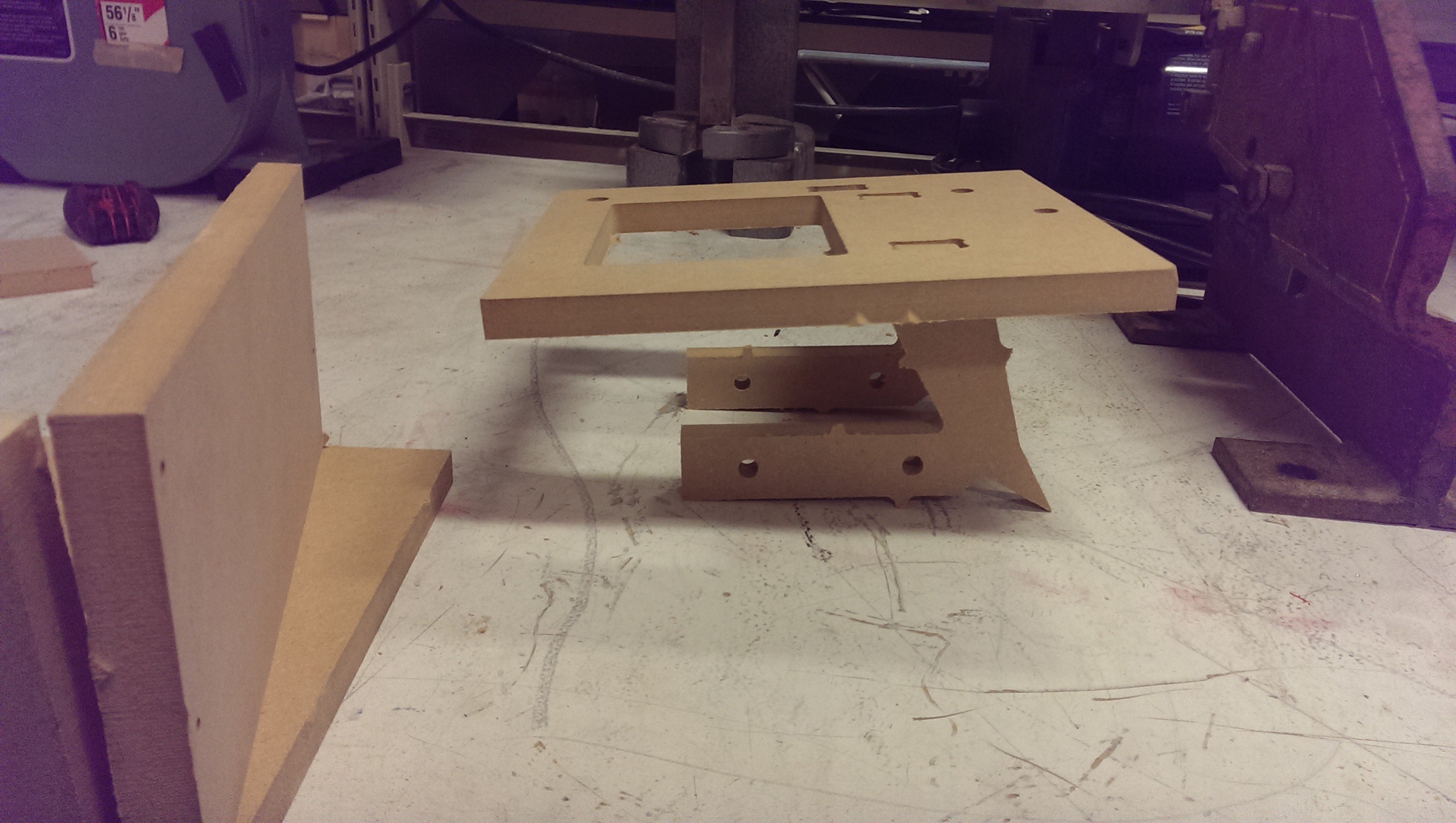
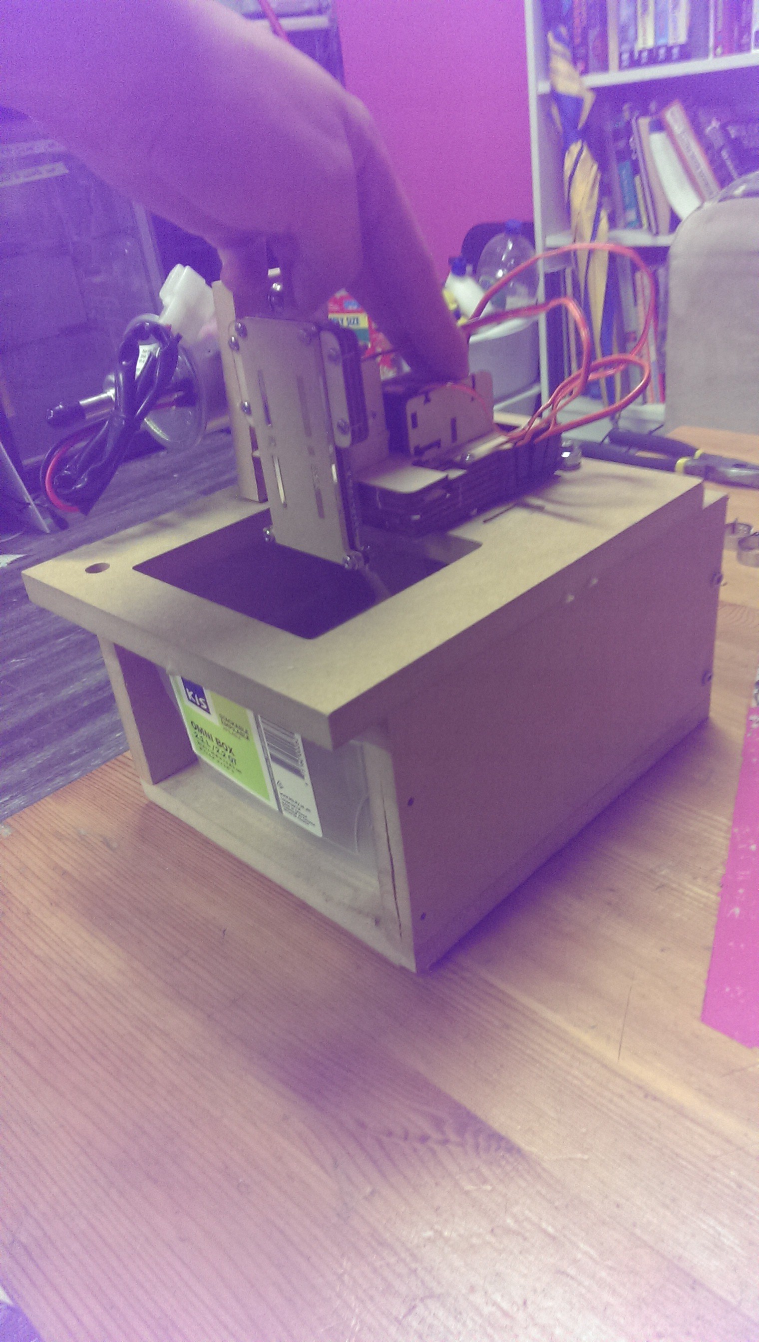
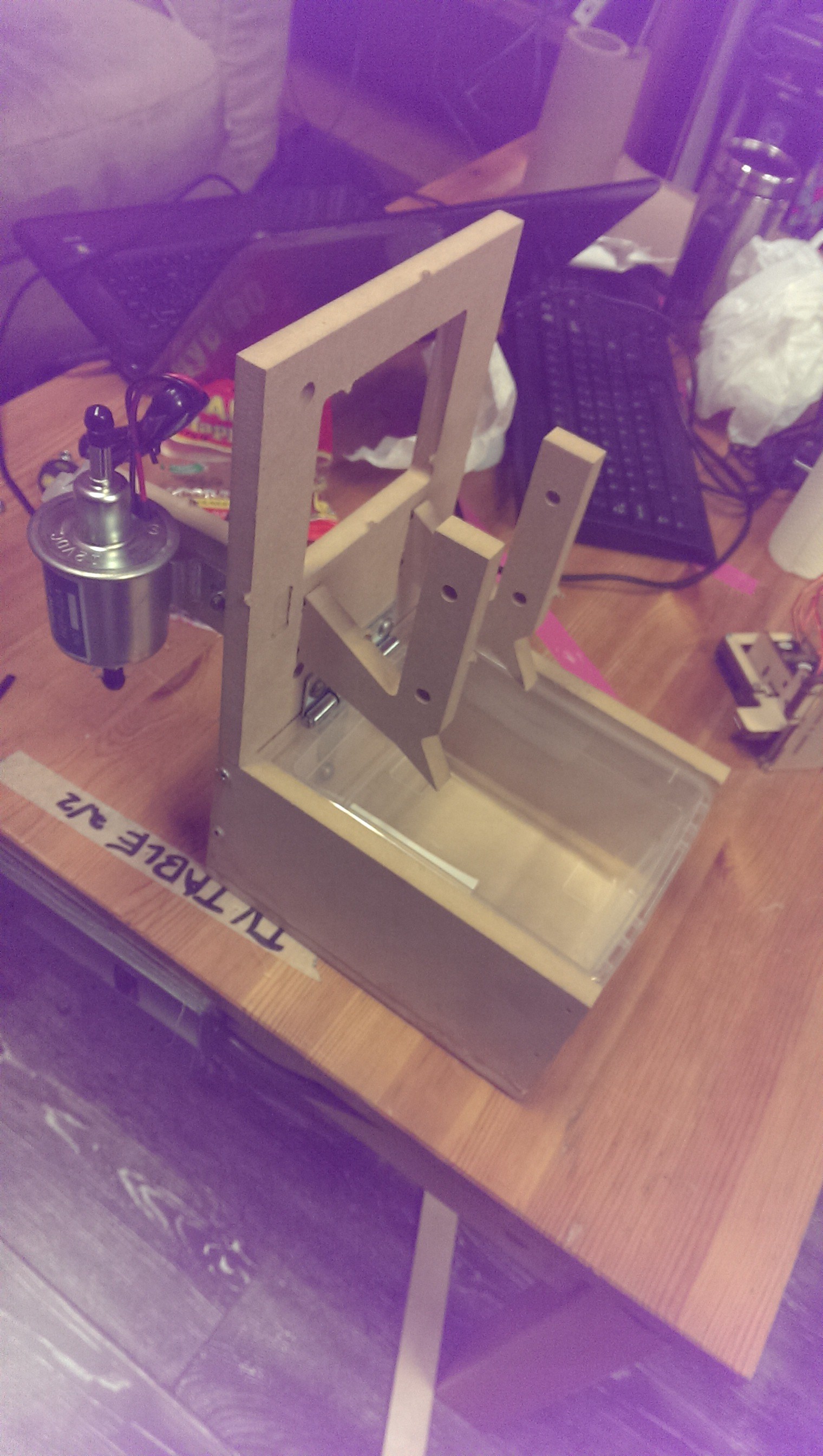
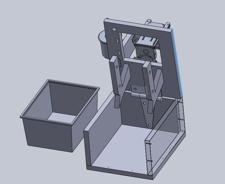
The rest of the frame is designed out of 1/2 inch MDF. The tank fits in the box, which can flip up like so:
![]()
And BAM. Hinges. The idea is that the whole mess can flip up for servicing, changing out the PCB, etc.
The PCB holders at the bottom might be changed a little before I build this, but the idea will stay the same. They'll be submerged in the EDM fluid in the tank during operation. Afterwards, the top flips up, and those PCB holders are angled so that the oil drips back into the tank.
That should mitigate oil going everywhere somewhat. I still expect this to get messy.
-
Well that was dumb
01/26/2015 at 07:47 • 0 comments90% of this project, I've gone ahead with hand tools or a soldering iron and just built stuff. Very little drawing out of stuff beforehand. That's my dayjob, planning ahead isn't fun.
So far the damage on this project has been two blown caps that I've over-volted, a bunch of wasted time building some motor drivers that ended up being too noisy (they would cause the microcontroller to brownout - I may fix this later, it's not too hard), and now a few more hours of wasted time.
I was getting some weird results with my power circuit (previous log), then I ran out of time and had to leave it for the day. Later in the shower, it hit me - duh. I was trying to drive the MOSFETs from the wrong voltage reference.
N-channel MOSFETs need a positive threshold voltage from the source to the gate. Usually (or often, I should say) they're going right to 0V, so my natural inclination is the drive the gate voltage using ground as the reference.
That's totally not what's going on in this circuit! Obviously! Here's a P-channel solution that I should have started with, given, like, 5 minutes of critical thought:
![]()
An incomplete survey of my hackspace tells me that I may have issues finding appropriate P-channel MOSFETs, though. They're much less common than N-channel. One of the local brick-and-mortar places has an old old list of transistors they used to stock in the 2000s, and that has one or two potential hits, both between $4-$6 per transistor :/
-
Bad news bump
01/18/2015 at 09:54 • 0 commentsSo I have't updated in awhile. I haven't lost interest or anything (quite the opposite).
Full story:
My hackspace(where I'm building this) got evicted a couple months ago. Everything got thrown into turmoil. A little while later, I got a frantic text message, "Pick up your shit!"
Heading down there a couple days later, well into the packing effort, to grab my project box, I couldn't find it where I left it. A little more effort turned up the distinctive blue box at the bottom of a shipping pallet, completely covered in shrink wrap.
Welp;
Anyway. We moved, we unloaded, and we're starting to unpack. The new place is a fair bit smaller than the old place, so we're in a purge phase.
And somebody purged my project box before I had a chance to grab it.
Through a completely offhand comment that someone made about finding a PicKit in the dumpster a couple days later, I rushed over and did some diving, recovering most of my project.
Whew.
I'm not sure the full extent of stuff I lost, but all of the important bits for this are okay, I think. Except for the power output stage, I couldn't find that board. It needed a bunch of rework, anyway.
The whole situation is ironic because it all happened the day before the hackspace is moved-in enough that I can work on stuff in there, for the first time in two months or so.
So I did some more work, rebuilding that output power board:
![]()
I've pretty much decided that this is a pre-alpha prototype, so I don't even care about the crappiness anymore. If every part of this project sort-of works, then I can prove my concept. After that, I start identifying the weak links and moving the project through a state of not-suck.
So this board: I left off the rectifier for now, so I'm not running it through my sketchy-as-hell antique transformer. I've swapped the order of the caps because I believe the mylar one will hold up better to repeated fast discharges. It's also a smaller value, so my pulses will be shorter, but be able to charge up as fast as the mylar cap can charge.
I'm still using simple red LEDs to indicate whether that stage has charge.
I still have to add bleeder resistors so that the system doesn't store energy while off. I have to add opto-isolaters to my micro to turn on the power MOSFETs.
I need some sort of analog readback at each of the stages.
The MOSFETs I'm using are totally unsuitable for this application, so I need to change them out. I'm not really happy at the selection of FETs at my disposal.
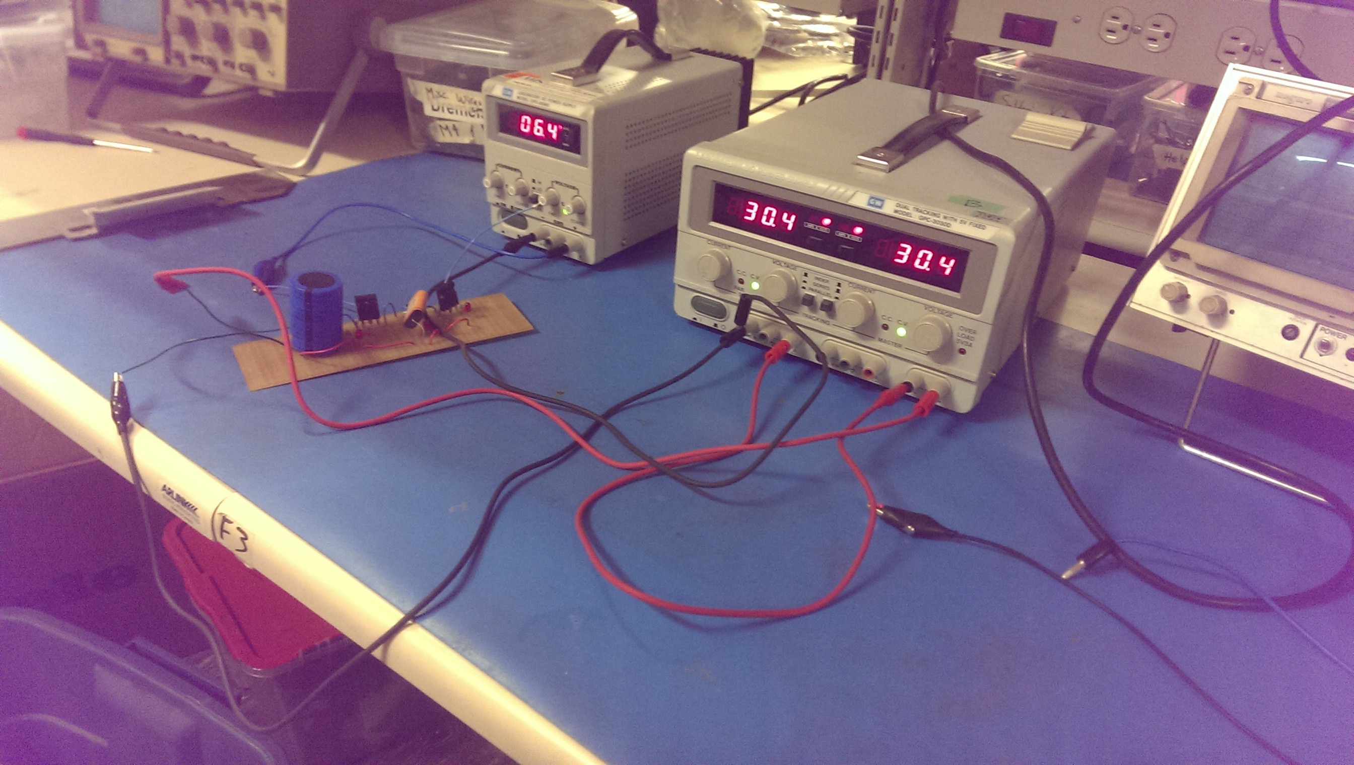
As you can see, without my xformer/rectifier, I'm just using a couple 30v power supplies in series (and another one to trigger the transistors). It's only 60v(my final circuit is 80v), but the principles don't change with the lower voltage.
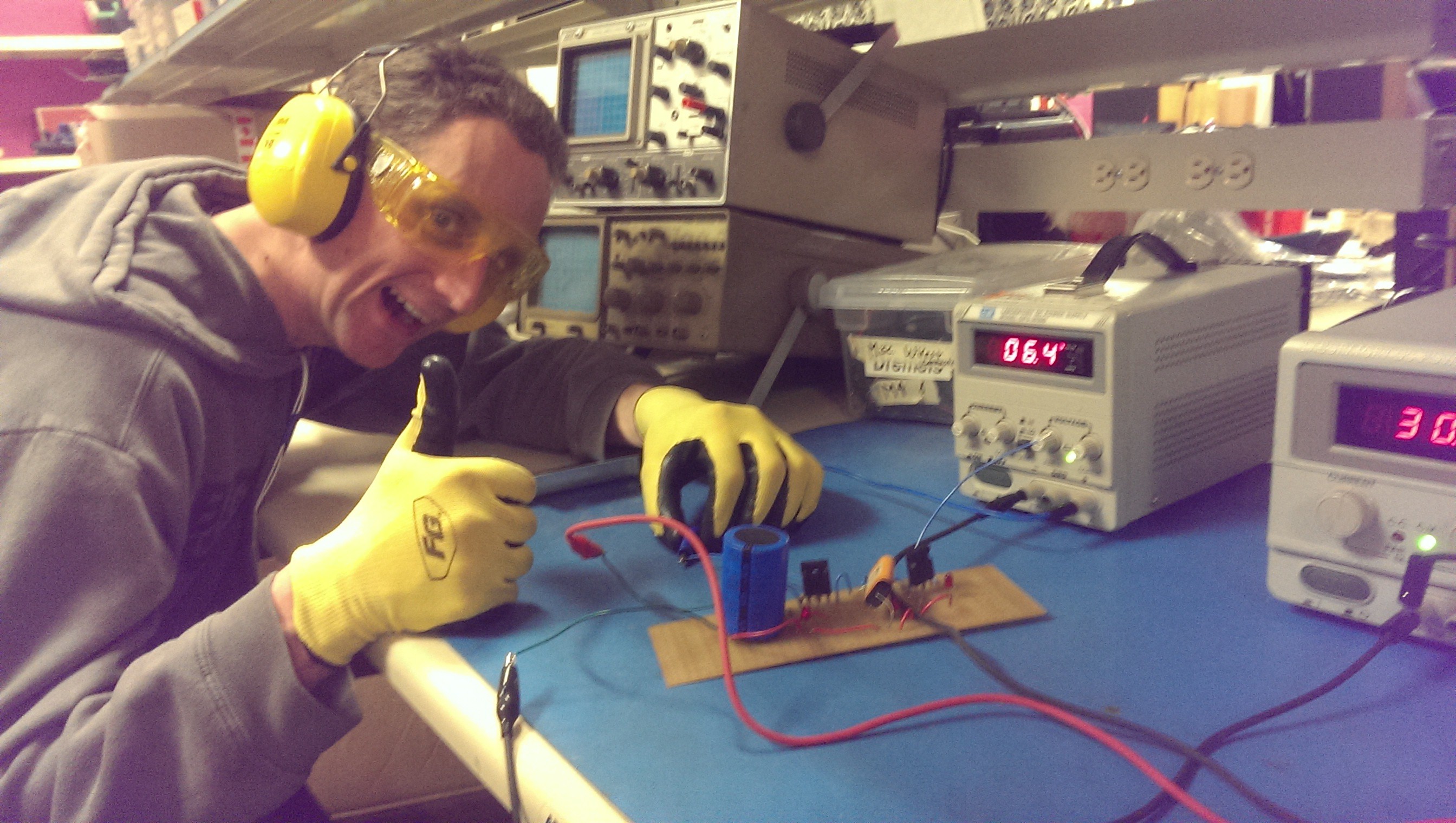
Bonus picture:
Whenever I'm feeling sketchy about a circuit, I get @TyIsI to touch the dangerous stuff!
![]()
-
MOSFET-life
11/14/2014 at 16:14 • 0 commentsHad some more time to work on this yesterday.
The Power section powers up! And nothing blows up!
The MOSFET family I'm using is the IRFBG30
I picked it out of the bin because all of the max values are acceptable, but there are some issues I need to keep in mind.
Foremost among them is that it takes 10v on Vgs to fully turn on. Max 20v on that junction. As it stands, I have a clean 5v rail and a dirty 80v rail. Eventually I may need a 12v rail for driving motors, but I'd like to put that off as much as possible.
The 5v section is isolated from this portion entirely, so I'll try using an optoisolator from my micro to feed 80v to a resistor divider, putting ~15v on the gate. How well this works will depend heavily on how well I can filter out the noise from arcing.
The transistor's max pulsed current is 12A, which is great (I plan on using 4A), but while I am technically doing pulses, it will be repetitive and as high duty cycle as my mechanical system will allow. These are rated for 2A continuous at high temperatures, so I may have to put to a couple in parallel.
If I come across a transistor that is slightly faster, lower Rds (this is 5 Ohm - too high!), lower max voltage but higher current, I would be pretty happy. Modern technologies are pretty great, I'm sure there are lots of options out there. I'm using components scavenged almost entirely from my hackspace's parts bins, however, so I am limited by what I can find.
That is made more difficult by the hackspace being in a state of flux at the moment after having our lease unexpectedly terminate recently.
-
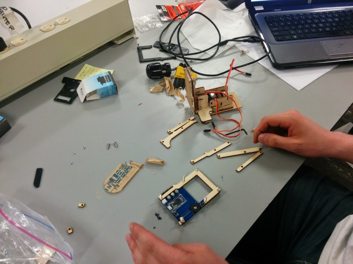
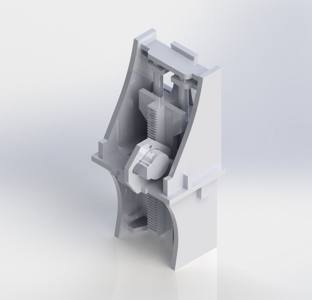
I like to move it move it
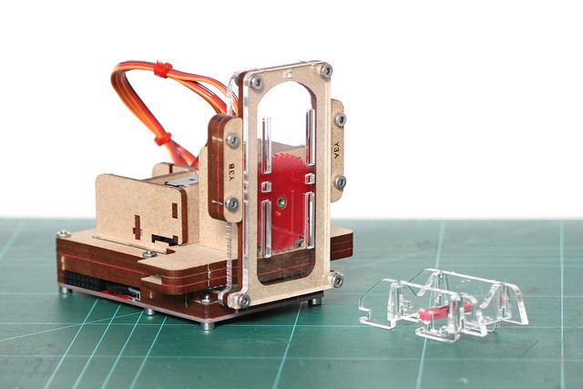
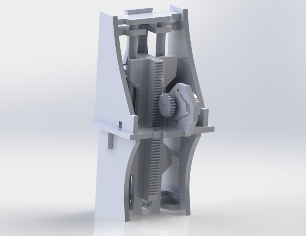
11/10/2014 at 22:42 • 0 commentsI also did this, like two months ago:
The idea behind this was a very cheap and quick Z-axis for controlling the spark. Basically when the electrodes get close enough with a high enough potential, then an arc gets created, ionizing the path between them. If you can get fine control of the up-down movement, then you can sustain this arc for a longer period of time, getting a better burn.
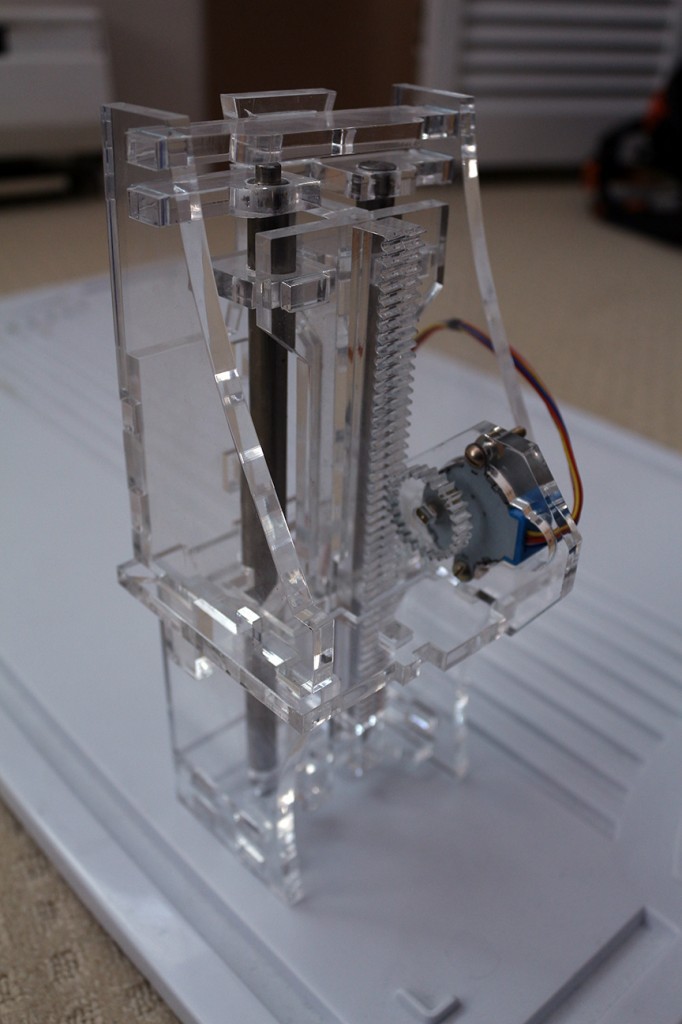
This took about 2 hours to mock up in SolidWorks, then 12ish to clean up and make sure it worked mechanically. 6 minutes to laser-cut out of 6mm acrylic, and then a couple hours to pressfit everything together.
![]()
![]()
![]()
![]()
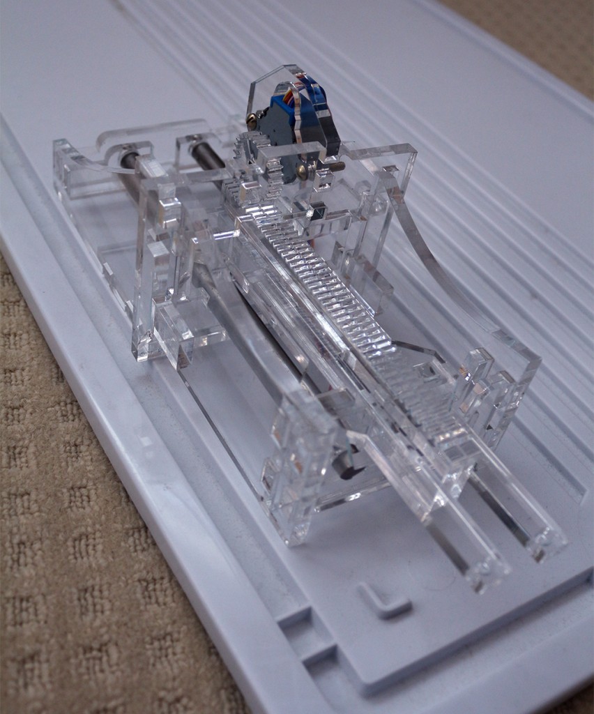
After building it, there are a couple problems. Next time I should do cutouts in my corners for laser cutting. The acrylic gets a little melty and it makes fitting pieces together a little challenging. That will also allow all of the tabs to fit in more thoroughly, helping the assembly keep in square and slide more smoothly.
I didn't use bushings on the linear rails. The rails came from a salvaged scanner, and I have the bushings, they're just encased in plastic and I haven't taken them out yet.
The backlash is also horrible with this design. I think that's going to have to change. Probably redesign at some point to use some threaded rod and homemade anti-backlash nuts.
Those motors are $2 eBay specials, but I made the mount for them reasonably modular to be swapped out with better ones.
-
Power! Almost.
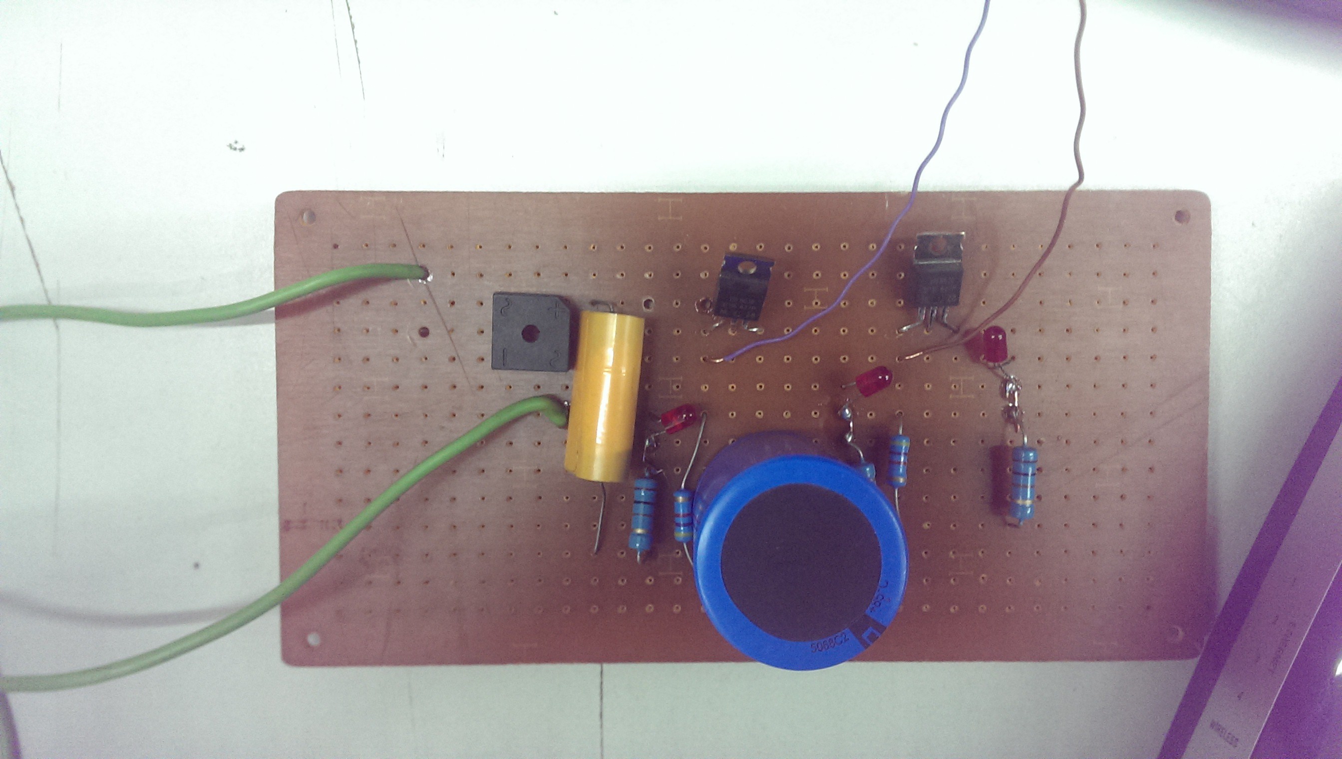
11/10/2014 at 22:15 • 0 comments![]()
Had a couple minutes to spend on this yesterday. This is the start of the power stage. It's pretty much like in that SPICE schematic I posted below, but with components I had lying around.
The idea is to pull max 10A from the wall at 120VAC. It goes through a 2:1 transformer (just left of this frame), and then through that square-shaped bridge rectifier in the top left. After that, I get about 80VDC, and it should be about 20 amps. It gets stored in that yellow mylar cap (side-note: I think I should change it to the same value or larger than the blue aluminum cap). Energy gets stored there, and then periodically transferred to the next stage through a MOSFET. I don't remember what the MOSFETs were, but the datasheet said it could handle ~10 amps with a 25ns rise time.
Energy then gets stored in the second stage, and the electrodes are in the third stage after one more MOSFET.
The idea is that I never want to open both transistors at the same time, potentially blowing a fuse when the electrodes short out.
There's also a red "DANGER!" LED at each stage.
Now that I think about it, that transistor should be fine for the 2->3 stage, but the first one will need to be able to pass 20 amps, probably. Then I need to limit current to 20A when cap 2 is depleted and transistor 1 first opens up, but doesn't limit current as much when cap 2 is half-charged, for example. A clever application of an inductor might be the solution.
As you can tell, I'm just plowing on and building things for this project. Finesse is for when I've finished a version 0.1 and want to start making it not-suck.
-
Sparky Sparky
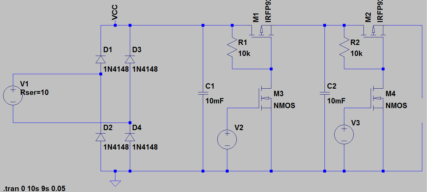
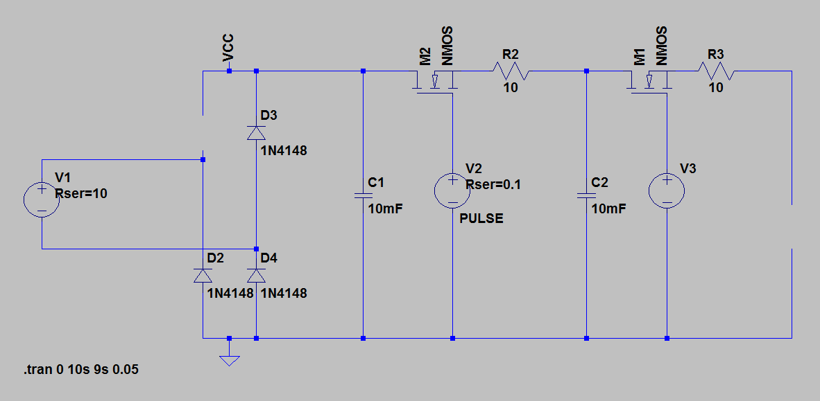
10/29/2014 at 07:20 • 2 commentsHere's the initial idea in LTSPICE for the power section. The input is from a 1:2 transformer, so around 60VAC, to 80VDCish. Electrodes are on the right. Obviously the MOSFETs will be driven from the PIC.
![]()
These values aren't anything close to final, I'm just playing around.
I'd like to add some sensing in there, too. Well, I need to, to know what's going on during a burn. I'll probably add some "danger" LEDs that turn on when the caps are charged up.
For measuring voltage and current, it's a little bit challenging when I need to keep the supplies isolated. I also don't particularly want to buy a fast isolated IC, and don't particularly need the precision.
I'm thinking PWM from PIC --> Optoisolator --> Big cap to smooth the PWM into an analog value --> comparator, added to the above schematic -> Back to optoisolator --> PIC Digital Input
That should get me a sort of homemade isolated 1-bit ADC.
-
A case for good enclosure
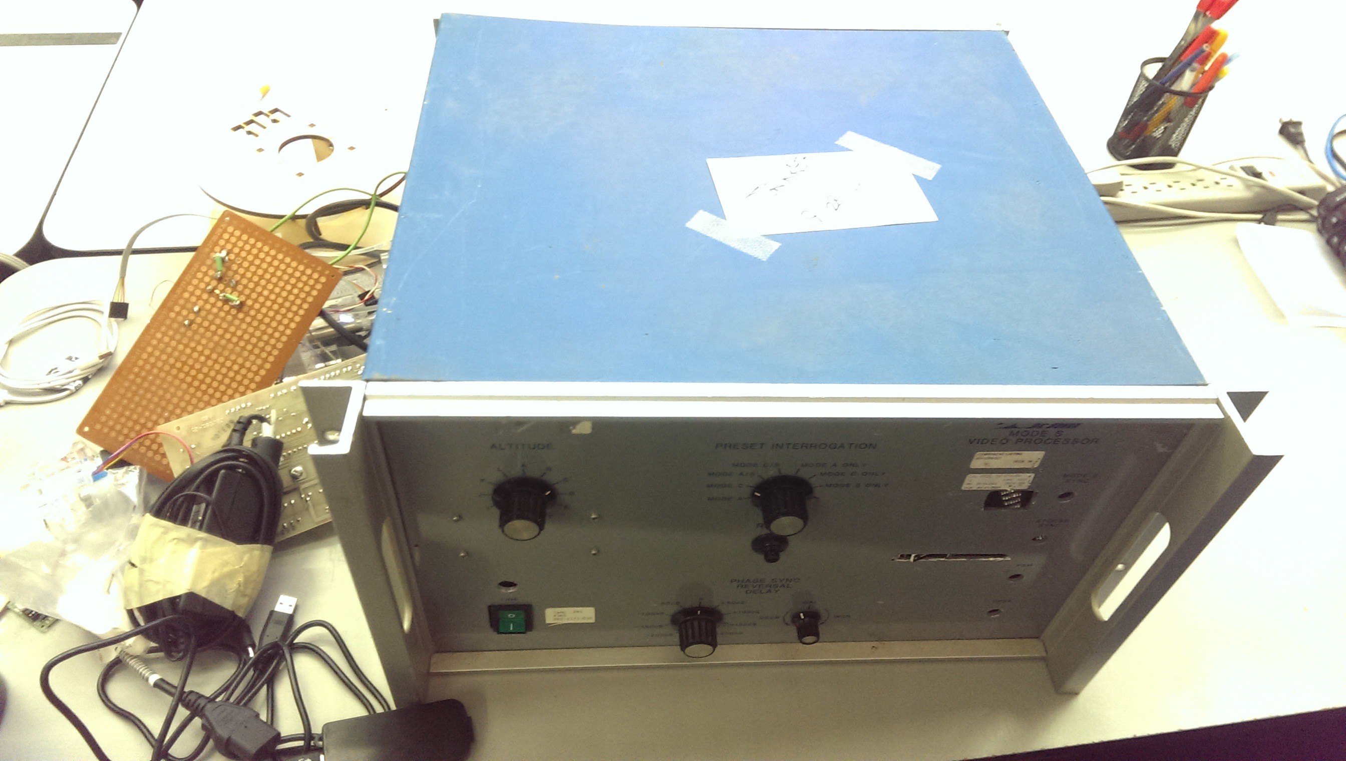
10/28/2014 at 21:09 • 0 commentsA member at my hackspace enlisted my help in clearing out some junk from his warehouse. I grabbed a cool-ass box. It had stuff in it, but after I took that out, there's plenty of room for me to put all my electronics crap into. Lots of room to work with, modular so I can replace panels with custom cut bits (when I know what components I want to mount), and comes with all sorts of cool switches and knobs that I'm totally going to try and work in where appropriate.
![]()
This is post-hacking on it for a bit. You can see some holes I cut for displays on the right, and the power switch on the bottom left is something I added.
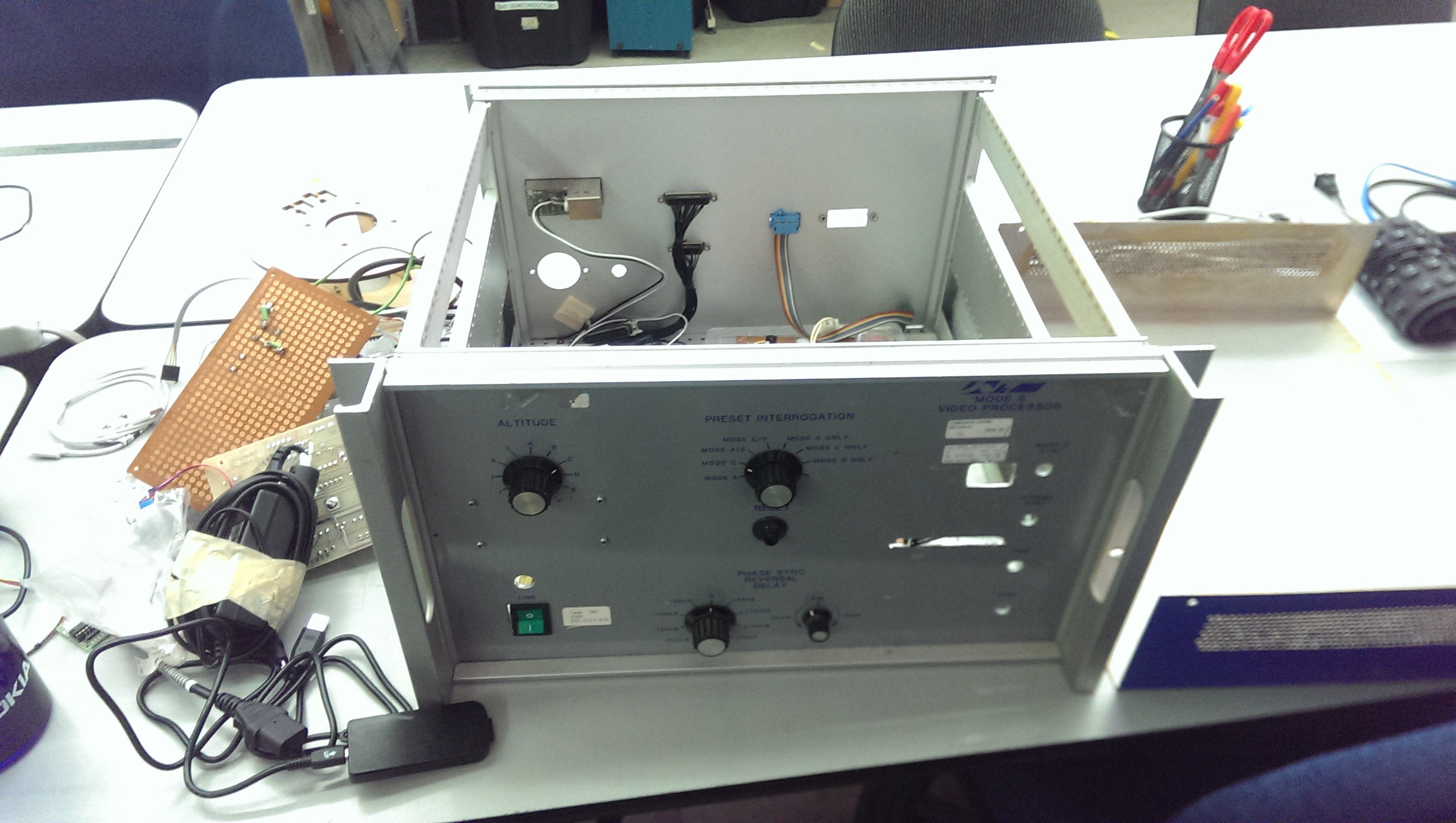
Top just slides off:
![]()
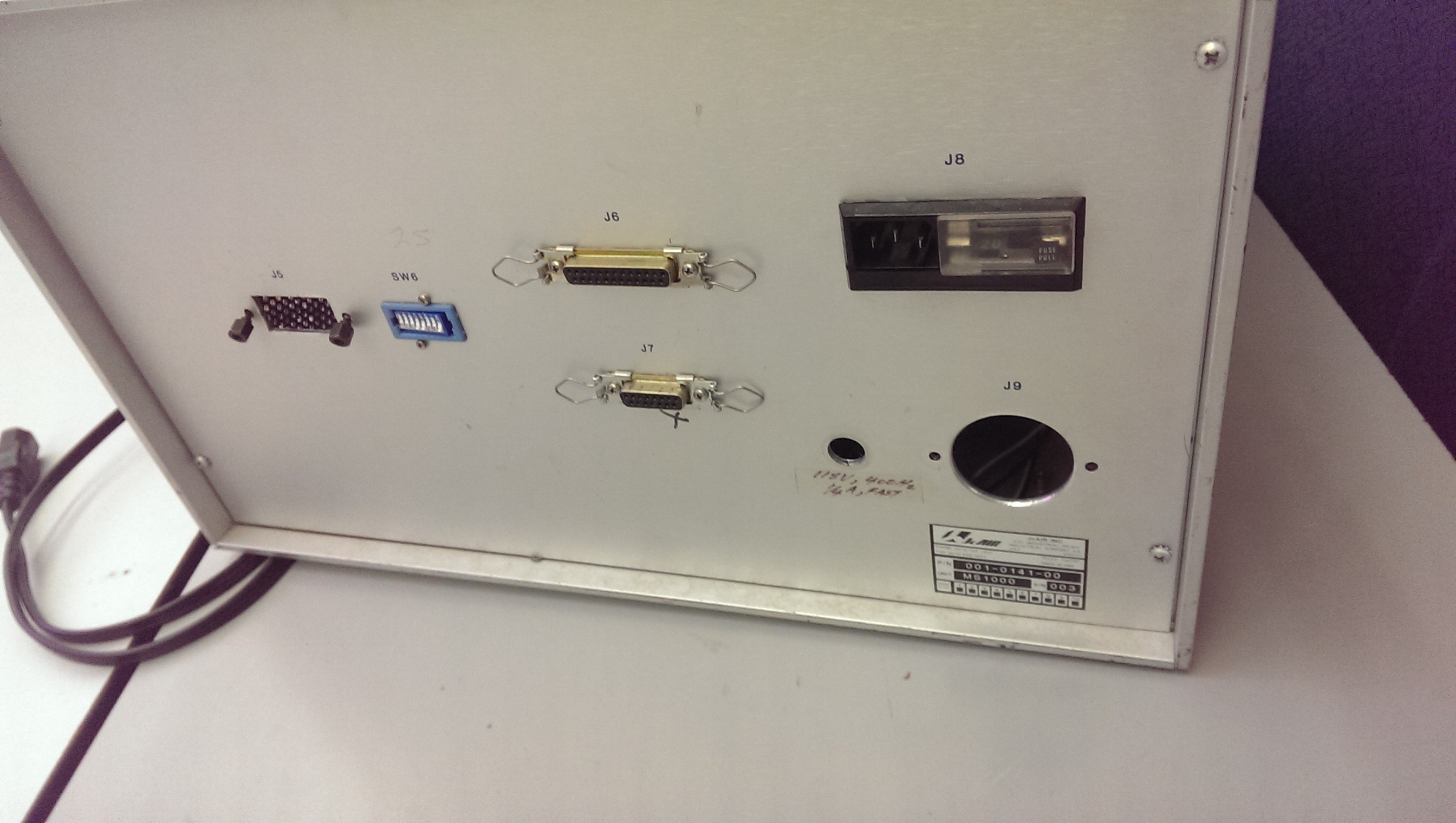
And around back, it came with an integrated fuse-holder and IEC power socket.
![]()
Note to future-Jarrett:
The fuse/socket unit claims to be rated up to 6A. I plan to eventually draw around 10A in pulses. If melts and catches fire, put it out, okay?
-
This is a many part project.
10/28/2014 at 19:14 • 0 commentsThere are three main categories in an EDM:
- The CNC system
- The electronics
- The fluid tank
I'm most comfortable with that electronics (that is kind of my thing), so I will start there.
The electronics can be broken up into two sections:
- The control side, and
- The power side
The power bit is the hard, industrial-trade-secret type thing that makes electrodes spark. I'm working on that, but I don't have a physical thing to show for it.
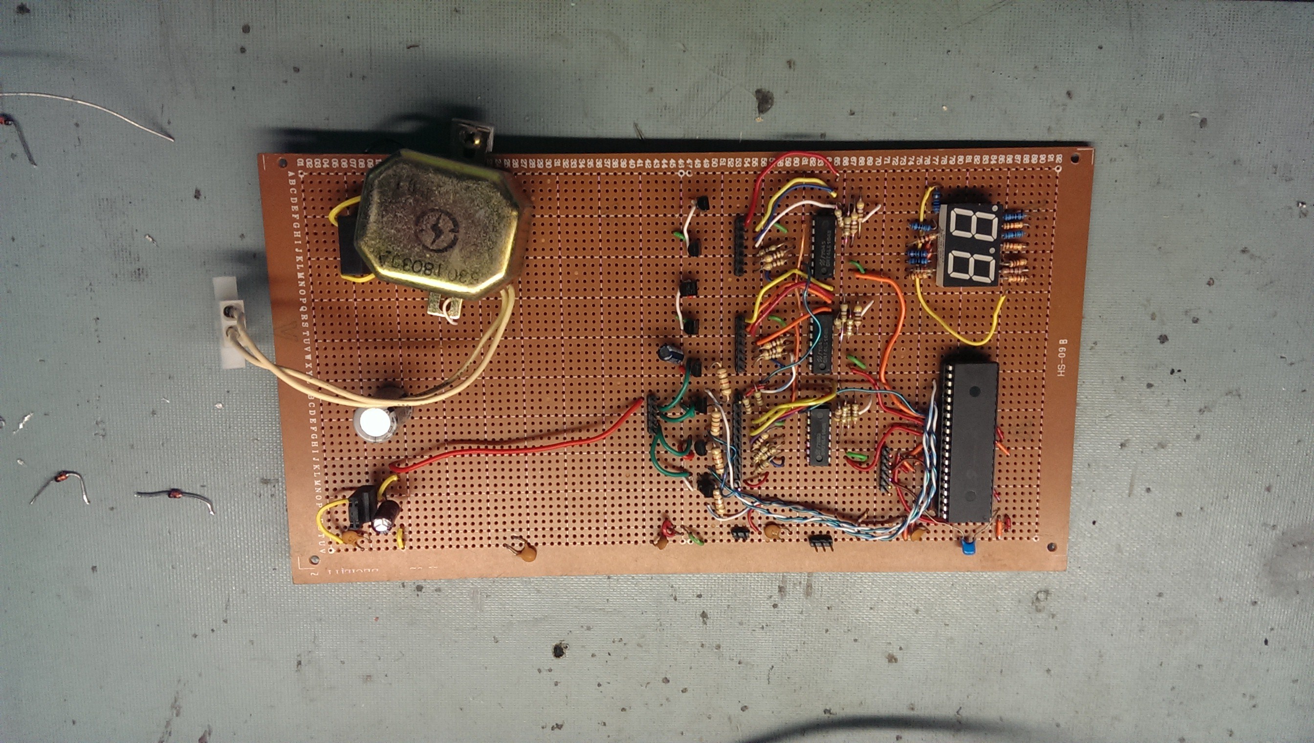
Here's what I have for control as of yet:
This will be hackish, and I've done many tens of hours on this and other parts already, so we're playing catch-up.
![]()
Left side: Transformer to 6-7VAC, full-wave rectifier, big cap, 7805 linear regulator
Right-to-left: PIC18F4320 microcontroller (one I had kicking around, a very beefy model ten years ago), dual 7-seg display that is no longer connected and I haven't finished desolder yet, a row of serial-to-parallel shift registers to drive LED displays in their new location, a row of not-fully-connected 2N2222 BJTs for motor drivers.
All of my control will be done in PIC, and I'll start keeping GitHub updatedish.
Not Your Father's EDM
No, not Electronic Dance Music - It's an Electro-Discharge Machine for PCB prototyping