Adam Fabio
-
Next Steps...
01/20/2014 at 03:39 • 0 commentsWhile I do have a working system, I still am not done with the project - I'd like to ditch the Arduino and use a PIC or AVR to drive the motor. I'd also like to get the entire assembly mounted in a more gauge like enclosure. Something that would look at home on a desk - well, at least among the electronics clutter of my desk.
-
Talking to the PC
01/20/2014 at 03:36 • 0 commentsNow with everything built and wired up to the Arduino, I had one last step. I needed to get my PC to share its processor utilization data with the Arduino. I figured I would be writing up some software in C# to do this, but found an even simpler way. LCD Smartie!
http://lcdsmartie.sourceforge.net/
LCD Smartie is software designed to send data from the PC to LCD's - usually monochrome character based or graphical LCDs. It contains drivers for several models of LCD and associated interface. I found that there was also a test driver, which I could modify with a format script. It was pretty simple to get the software to open the arduino's com port and send down simply a sync token (a semicolon in my case) and the processor utilization. The arduino then used that data to determine where to position the pointer.
http://www.youtube.com/watch?v=AedCPZO8LsM
-
Putting a Face on a Gauge
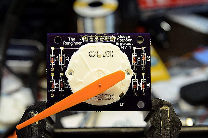
01/20/2014 at 03:30 • 0 commentsWith the PCB and parts finally back, and working pointers printed in safety orange, I started assembling.
![]()
About 10 minutes of soldering later, the finished board looked great
![]()
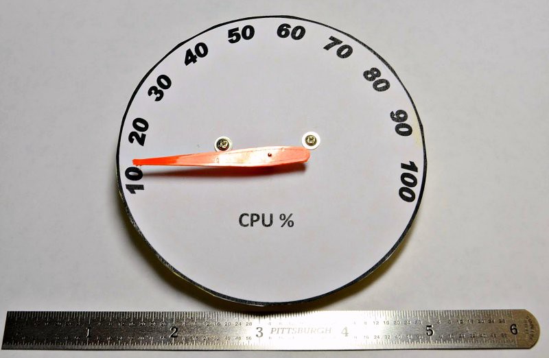
Now I needed a face for my gauge. I broke out word for windows (I know, I know) and quickly threw together a quick gauge face. This is a place where there is plenty of room for improvement. I didn't even put a 0% position on my gauge face!
![]()
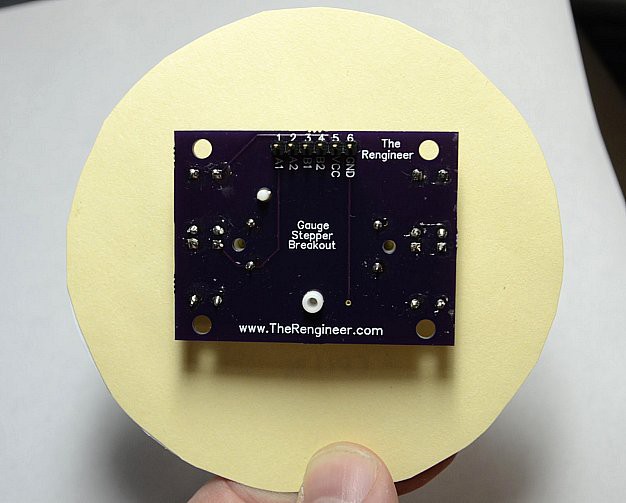
The Switec has holes for two screws to attach the gauge face. Servo screws, commonly included with standard sized hobby servos proved to be a perfect fit. Two of them tapped right into the plastic of the Switec motor, solidly holding the face to the gauge. I did find that heavy stock paper alone was a bit thin for the task, so I broke out the glue sticks and added some oaktag folder stock for a backing.
![]()
-
Of Pointers, Pins, and Needles
01/20/2014 at 03:18 • 0 commentsWhile the PCB's were being built, I turned my attention to the pointer issue. The switec motor's have a 1mm shaft. A good pointer has to be a press fit on the shaft, but not so tight that the mild steel motor shaft is bent while pressing the pointer on! It also had to be loose enough that the pointer could be re-positioned without destroying the motor's clockwork drive train. Switec's datasheet called for a very specific lobed triangular hole. The hole allowed for three points of contact between the shaft and pointer body. It was also damn near impossible to create without an injection molded part or a very accurate 3D printer.
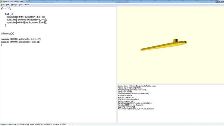
To make things work, I decided to put my personal 3D printer to the test. I designed a pointer in openSCAD.
![]()
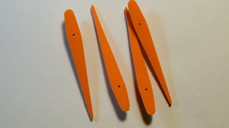
Then printed it out on my RepRap Prusa. The holes designed into the part closed up during the printing process. Knowing my printer's capabilities, I expected this. My hope was that the small amount of plastic closing up the hole would act as a guide for a drill bit.
![]()
I drilled out the holes with a #62 twist drill on my milling machine. Because of the physics of plastic melting while it is drilled, It took a bit of trial and error to learn how to best speeds to drill. In the end, I hand fit each pointer to a sample motor, drilling a bit more when needed to arrive at the perfect fit. A bit of sanding on the edges of the pointers also cleaned up any leftover strings from the printing process. Thanks to the 8 inch bed on my printer, I was able to print 11 of the pointers at once.
-
Designing a PCB
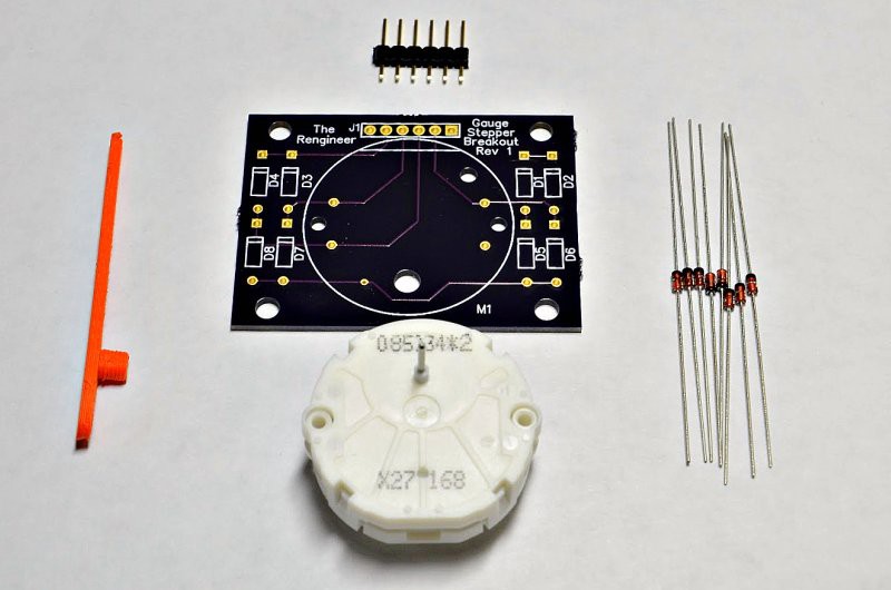
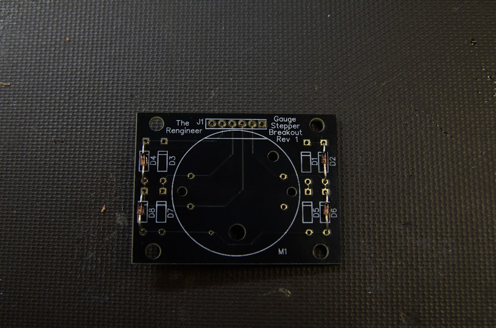
01/20/2014 at 02:55 • 1 commentI designed my PCB in my favorite software - Diptrace. The motor footprint from switec's datasheet was missing a few key dimensions. It took a bit of measuring with a caliper and calculating hole sizes, but I was able to get all the dimensions correct on the first rev
![]()
I also installed some flyback diodes. Each time the motor's coil is switched on and off, there is an inductive spike created. 8 diodes direct these spikes to the power rails, protecting the output pins of the microcontroller driving the motor. I added a standard .100 header, some all important mounting holes, and sent the design off to OSH park.
-
Prototypes ahoy
01/20/2014 at 02:48 • 0 commentsWith motors in hand, I built up a quick prototype. The X27 motors are designed to only move a small pointer. They draw so little current (under 20ma at 5v) that they can be driven by PIC and AVR micro pins directly. Soldering wires to the thin pins of the motors can be a chore though, so I used a bit of strip board as a holder. I wired everything up to an Arduino Uno and ran Guy's code. The motor moved... but it was pretty hard to tell with just a piece of tape wrapped around the motor shaft. Prototyping showed I needed two things: Pointers and a PCB.
-
First Steps
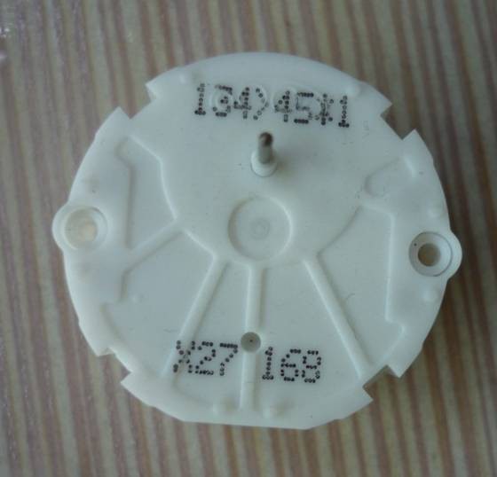
01/20/2014 at 02:25 • 0 commentsMy first steps were to get my hands on a motor. I started with the X27.168 motor, seen here.
![]()
There are a couple of variants of these motors. The 168 motors have the pins exiting on the back of the motor, while the drive shaft exits on the front. The 589 motors have the pins exiting on the same side as the drive shaft. Both versions have plastic pins used to hold the motor into its PCB. I grabbed a set of each motor, and decided to go with the 168 series.
Analog CPU Gauge
An analog gauge to show your computer's CPU utilization