 zakqwy
-
1Step 1
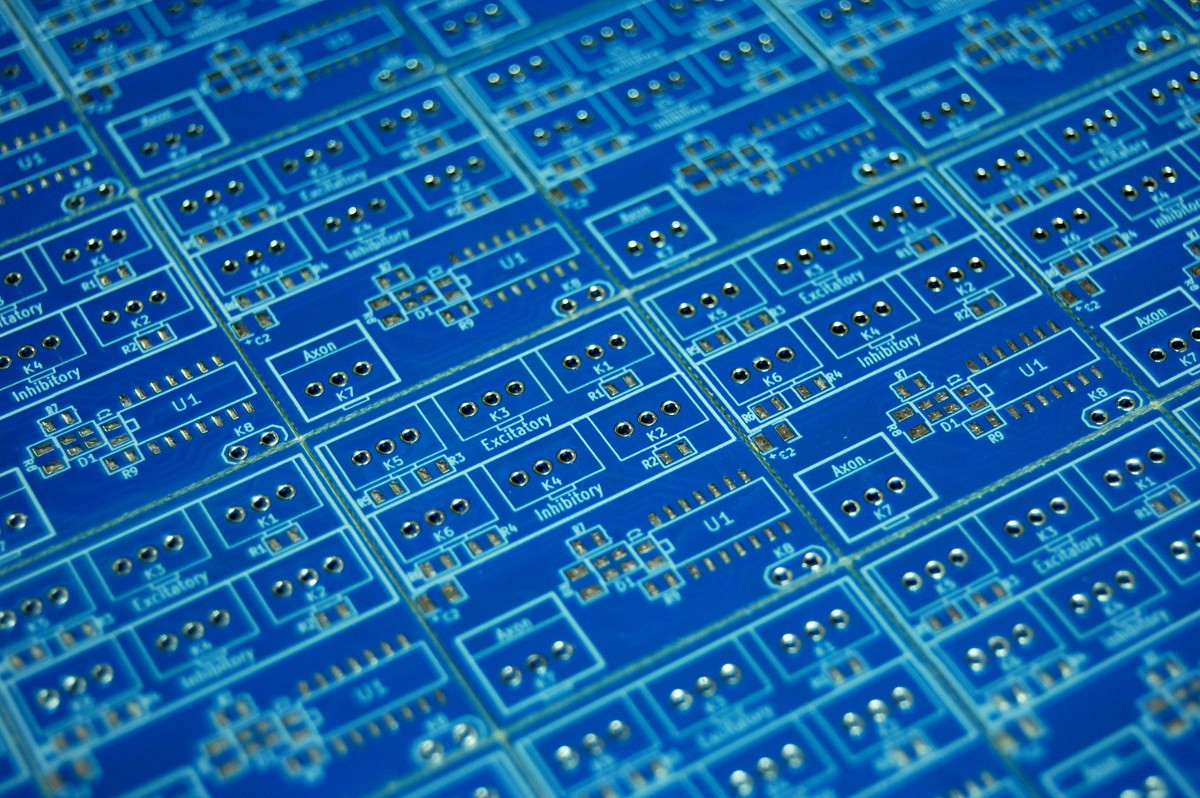
Get your hands on some NeuroBytes v04 boards.
![]()
You can grab the gerber files from the GitHub repo, and either etch the boards yourself or send them off to a place like OSHpark or DirtyPCBs for fabrication. I also have a number of individual boards left over from our production run, since we had a panel fail E-testing with a single problem (meaning 31 elements were still good). Drop me a line and I'll send a few your way, as we're pretty much done making v04 devices at this point.
-
2Step 2
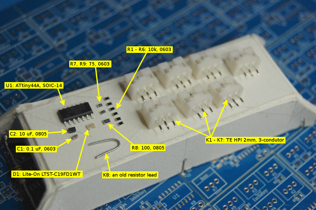
Obtain all parts listed in the 'Components' section of this page.
![]()
- Make sure you get the ATtiny44A model that comes in the 14-pin SOIC package.
- You might be able to substitute a different RGB LED, but make sure it has the same pinout as the cheap units I used.
- The passives are all pretty run-of-the-mill; you could probably swap different 0603 pulldown resistors in if you have something else on hand. The other resistors are specific to the various LED channels, so make sure they're correct.
- The larger filtering capacitor only seems to be necessary if you're directly powering servos using the Motor NeuroBytes firmware.
- Make sure you get the correct connector headers; the TE Connectivity devices I specified use 2mm spacing, which will seem small if you're used to 0.1" stuff.
-
3Step 3
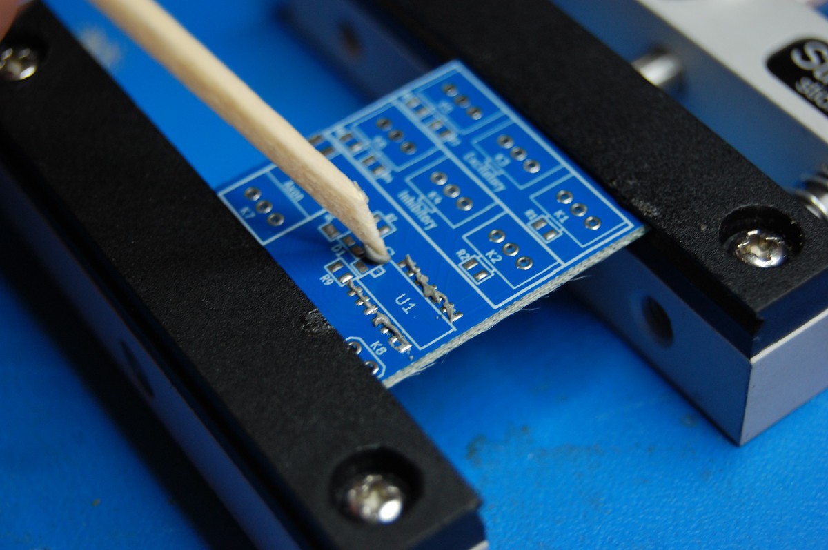
Apply solder paste.
![]()
We follow RoHS guidelines (the bare boards, even at the prototype level, were always destined for a classroom, so avoiding lead seemed prudent); as such, we used Chip Quik no clean Lead-Free from a syringe. You can use pretty much anything here, just make sure your board of choice is rated for the required reflow temperature.
Applying solder paste with a trimmed down matchstick seems to work pretty well. I generally run a line of paste along each side of the microcontroller, letting the solder mask work its magic to avoid bridges. The toughest part seems to be the LED; its leadless nature means if the quantity of solder on each of the four pads isn't consistent, you might miss one of the terminals and end up with RG (or RB or GB) device.
Or you could be smart and make a damn stencil. I hear kapton stencils are cheap. If you do this let me know and I will send you mad Internet kudos.
-
4Step 4
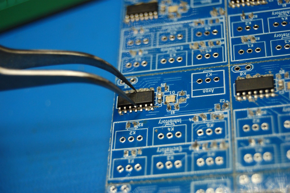
Place components.
![]() I usually start with the IC and work my way out. Make sure you get the polarity correct on the microcontroller, LED, and (if used) larger filtering capacitor. Seriously, my biggest source of scrap during production wasn't bad solder joints; it was backwards ATtiny44As. Watch the dot!
I usually start with the IC and work my way out. Make sure you get the polarity correct on the microcontroller, LED, and (if used) larger filtering capacitor. Seriously, my biggest source of scrap during production wasn't bad solder joints; it was backwards ATtiny44As. Watch the dot! -
5Step 5
Reflow.
![]() I use a modified toaster oven to reflow NeuroBytes, usually 8 or 12 at a time. It's not perfect; I usually watch the parts through the oven's window and sometimes need to manually extend the cycle to ensure everything reflows properly. I also tend to overcook NeuroBytes, which is why some are bright blue and others are a bit faded (scorched). Either way, I recommend following the reflow profile for your solder paste, or just manually switch the oven off when stuff starts to get shiny.
I use a modified toaster oven to reflow NeuroBytes, usually 8 or 12 at a time. It's not perfect; I usually watch the parts through the oven's window and sometimes need to manually extend the cycle to ensure everything reflows properly. I also tend to overcook NeuroBytes, which is why some are bright blue and others are a bit faded (scorched). Either way, I recommend following the reflow profile for your solder paste, or just manually switch the oven off when stuff starts to get shiny. -
6Step 6
Insert, solder, and trim headers.
![]() The headers have slightly bent leads, meaning they conveniently hold themselves snugly to the PCB while waiting to be soldered. As with the active components, make sure you watch orientation; the silkscreen clearly shows which side should get the header tab, but I've still messed it up before. Don't apply too much heat while hand-soldering or you'll melt the plastic around the header and start throwing the pin orientation out of whack.
The headers have slightly bent leads, meaning they conveniently hold themselves snugly to the PCB while waiting to be soldered. As with the active components, make sure you watch orientation; the silkscreen clearly shows which side should get the header tab, but I've still messed it up before. Don't apply too much heat while hand-soldering or you'll melt the plastic around the header and start throwing the pin orientation out of whack.After soldering, I also use a pair of flush-cutting diagonal snips to trim the solder joints flat with the bottom of the board. The joints probably won't pass NASA spec (which is quite particular about insufficient lead protrusion), but I haven't had any issues with connector breakage even with significant handling. YMMV if you don't use plated-through boards, I suppose; in any case, this step really saves the table (and your hands).
-
7Step 7
Build some accessories.
![]()
Depending on what you're trying to do with NeuroBytes, you'll likely want some accessories; at minimum, I recommend putting together one power supply and one each of Exciters and Axons per board. You're realize pretty quickly that things get a lot more interesting once NeuroBytes can talk to the real world, so I also recommend putting together a few switches of various sorts (PCB and snap-action are both perfect).
![]()
Oh yeah, and build a programming harness. Use a mini-grabber to connect to K8 (the ATtiny RESET pin). My harness has programmed 100 NeuroBytes to date and seems to be a decent solution. If you're only doing one, you could probably jury-rig something with a few axons and an alligator clip. Note the built-in AVR ISP adapter--super helpful, now it plugs right into my programmer!
-
8Step 8
Programming time!
![]() There are tons of ways to program an ATtiny44A; I happen to use Adafruit's excellent USBtinyISP, along with a few Linux command line tools (Make, VIM, etc). LadyAda has a great set of tutorials that can point you in the right direction; if you happen to be using the same setup, the Makefiles (and everything else) in the GitHub firmware directory is pretty much all you need. If you're using AVR Studio and a commercial programmer, you can reuse the 'main.c' files and set the fuses according to the Makefile.
There are tons of ways to program an ATtiny44A; I happen to use Adafruit's excellent USBtinyISP, along with a few Linux command line tools (Make, VIM, etc). LadyAda has a great set of tutorials that can point you in the right direction; if you happen to be using the same setup, the Makefiles (and everything else) in the GitHub firmware directory is pretty much all you need. If you're using AVR Studio and a commercial programmer, you can reuse the 'main.c' files and set the fuses according to the Makefile.When you first build a board, hit it with v04test_LED to make sure the LED is soldered correctly; if it is, the board will light up bright WHITE. After that, choose the NeuroBytes runtime program you want to use; most will stick with v04run_standard unless you're playing around with servos.
-
9Step 9
Try building a few neural circuits!
Starter ideas:- Basic ring oscillator: 5 NeuroBytes in a continuous loop.
- Self-extinguishing loop.
- Randomly connected NeuroBytes that do crazy things (you'll want some Axon Terminals to do this well).
Once you get a few servos and reflash a few modules to be Motor NeuroBytes, you can do a lot more!
 I usually start with the IC and work my way out. Make sure you get the polarity correct on the microcontroller, LED, and (if used) larger filtering capacitor. Seriously, my biggest source of scrap during production wasn't bad solder joints; it was backwards ATtiny44As. Watch the dot!
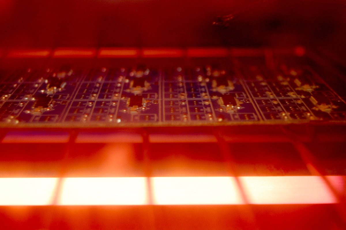 I use a modified toaster oven to reflow NeuroBytes, usually 8 or 12 at a time. It's not perfect; I usually watch the parts through the oven's window and sometimes need to manually extend the cycle to ensure everything reflows properly. I also tend to overcook NeuroBytes, which is why some are bright blue and others are a bit faded (scorched). Either way, I recommend following the reflow profile for your solder paste, or just manually switch the oven off when stuff starts to get shiny.
 The headers have slightly bent leads, meaning they conveniently hold themselves snugly to the PCB while waiting to be soldered. As with the active components, make sure you watch orientation; the silkscreen clearly shows which side should get the header tab, but I've still messed it up before. Don't apply too much heat while hand-soldering or you'll melt the plastic around the header and start throwing the pin orientation out of whack.
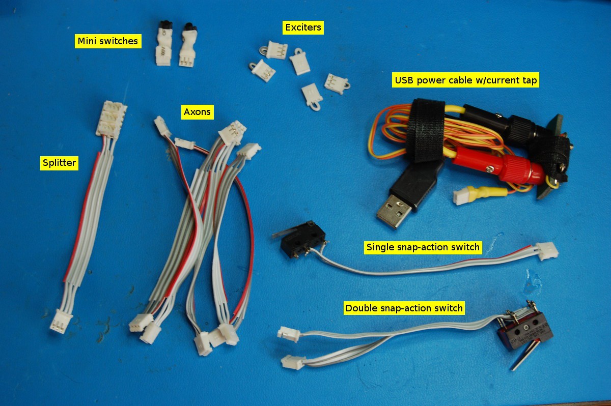

 There are tons of ways to program an ATtiny44A; I happen to use Adafruit's excellent
Discussions
Become a Hackaday.io Member
Create an account to leave a comment. Already have an account? Log In.