Kickstarter: 3 years of tedious planning, a month of frantic promotion, and a lifetime of apologizing for delays. This is hard and I am not very good at it, but we continue to move forward.
I recently posted our fifteenth Kickstarter update since the campaign finished over a year ago. As an aside, you may have noticed a distinct lack of posts on this project page; that's because I really owe our backers the first word, and I often lack the bandwidth to document the project in a few places simultaneously. I have a backlog of interesting technical challenges I will get around to discussing here at some point. Hopefully.
Jarod and I went to China earlier this year. To be precise, we crossed the International Date Line en route to Hong Kong around 5:00 PM local time on December 31st, so you could argue that we are still in 2018:
In any case, as I detailed in the aforementioned log update, the run went well. Really well! A lot of things came together at the last minute and we're even a bit proud of how some parts turned out (other parts, like the recycled packing material I specified, maybe a bit less so). But one part went distinctly less well, best illustrated by this traumatizing gif:
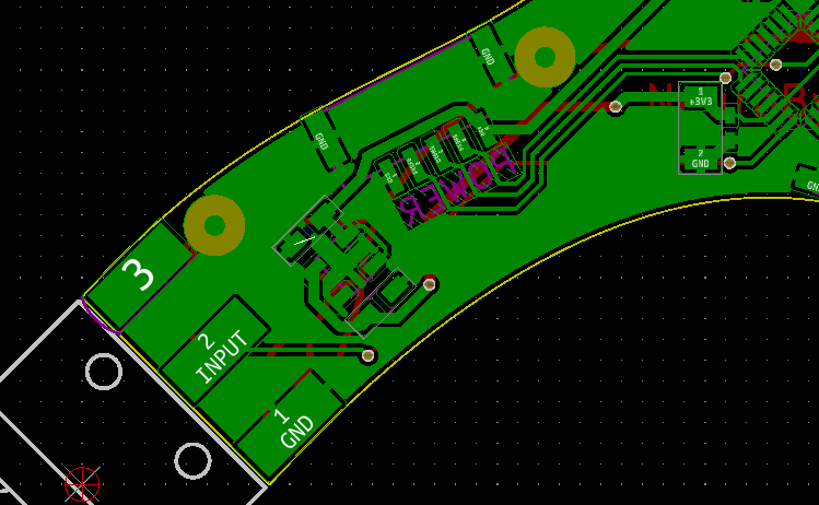
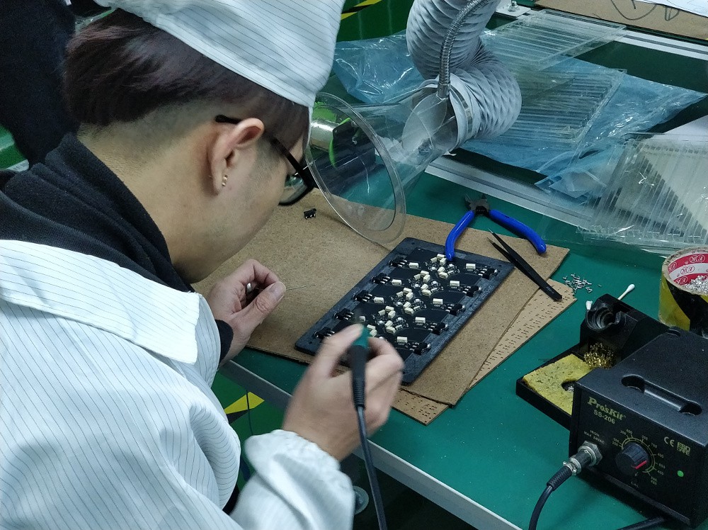
See what happened? At some point, I rotated the regulator footprint 90 degrees and repoured the ground planes, meaning the only evidence of the mistake was the now-visible ratnest. Well, that, and the DRC errors I would have gotten if I'd run a DRC as my absolute last step prior to fab file export. It meant we had to scrap all the Touch Sensory Neurons (a bit over 10% of the run), and this poor chap will need to re-solder switches on all the new PCBs once he gets back from Chinese New Year:
Lesson learned, the hard and expensive way. I even prototyped this board a few months earlier; I need to review my commits, but I believe the issue came up when I changed my SOT23-5 footprint in the library and then reloaded my netlist and replaced footprints. Ugh. DRC EVERY TIME, PEOPLE.
Moving on. The Chinese New Year comment above came about yesterday, after my manufacturing partner let me know they wouldn't be able to source all the parts prior to the holiday and our run (and thus ship date) would be pushed back to mid-February. Back in China, Jarod and I still hoped to solve the problem fast and get our Kickstarter fulfilled before the break. We pulled an inventory report and realized the run overage wouldn't cover a few components, including the STM32L0, the rear-mount RGB LED, and the snap-action switch. Sunday morning, we hired a car to take us from Dalang, Dongguan to Huaqiangbei, Shenzhen.
China is .. hard to describe. Jarod and I only saw a tiny slice of the massive country, from a tiny perspective, for a tiny amount of time. If you're interested in electronics, try to figure out a way to get to Huaqiangbei, Shenzhen; if you're interested in any other consumer goods, you probably should go somewhere else, as there is likely a massive city built around its supply chain somewhere in the country.
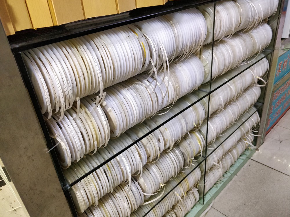
Our driver laughed as I excitedly took pictures of the LED signs showing spot pricing for various electronic components. We learned that in Huaqiangbei, it's pretty normal to see dropped SMT components and bits of tape on the ground, and most blocks feature a few people carrying around stacks of reeled parts.
Pollution is A Thing in China; when I took this picture from the 23rd floor of the Huaqiang Plaza Hotel, the AQI was around 150 and a decent number of folks wore face masks. Some parts of the surrounding area are quite clean (particularly restaurants, hotel rooms, lobbies, and the like), but many hard-to-reach surfaces have a bit of grime on them; it's especially visible on windows and polished metal surfaces. I imagine this is related to airborne particulate pollution.
We headed for the Golconda Electronics Market. This building, a 6-story electronics bazaar of sorts, is adjacent to the Plaza Hotel and seemed like a good starting point. As you go higher in the market, you pass through the passives section, to microcontrollers, to assemblies, and finally to LCDs.
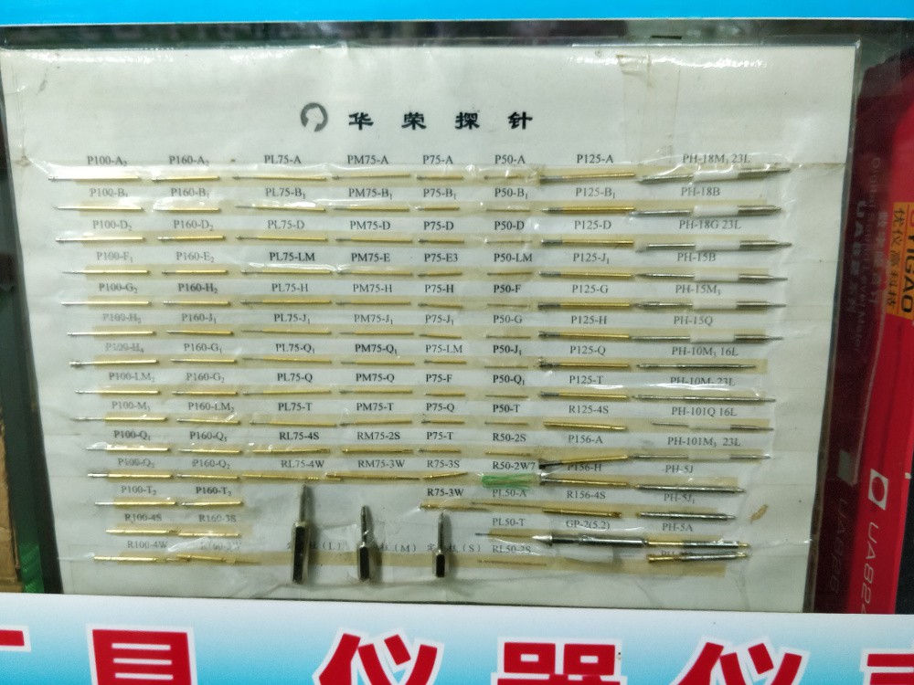
Some stalls, like the one shown above, had hundreds of reels mounted to the outside of the shop, presumably so you could examine the parts close up and maybe take samples. Others, like the pogo pin vendor shown below, kept their samples behind glass:
On Sunday, many of the vendors were closed, so we felt okay taking pictures of the displayed products. When we returned later that week, the building buzzed with activity; many aisles were completely blocked by teams of workers efficiently boxing up stacks of reels for shipment. Golconda, and Huaqiangbei in general, is a place for serious business, and the vendors aren't tour guides. If you do visit, be respectful of people's time, stay out of the way, and only engage if you're serious about making a purchase.
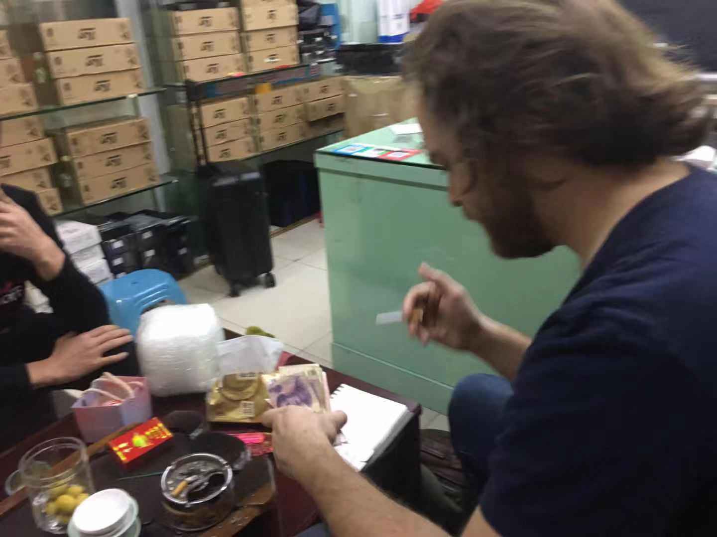
Soon, we came across a booth plastered with ST logos. The windows were blocked by stacks of boxes bearing the company's logo; mostly STM32F0 and F1 series parts, with a few STM8s sprinkled in for good measure. We knocked on the door and introduced ourselves to the vendor and showed him the part we wanted to purchase: STM32L011, qty 750 (a few extra for good measure). He immediately motioned for us to sit down on his couch, gave us cigarettes, and sat down at his computer. A few minutes later he got up, scrawled a per-piece price on a bit of paper, and indicated that we could pick the parts up in a few days, but he'd need a deposit.
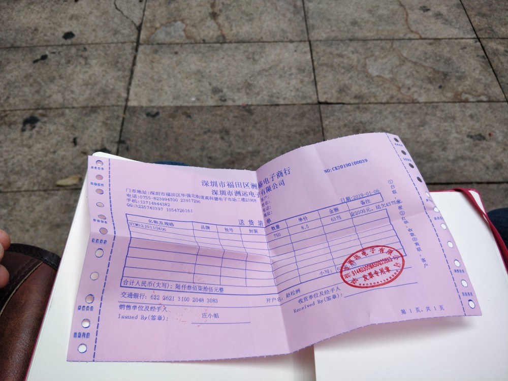
The picture above is a bit blurry, but hopefully you can see the important parts: Cigarette. ST boxes in the background. Tea table. Cash for a deposit. And bunnie's invaluable point-to-translate guide. We asked for a receipt, which he provided but it was clear to us that this wasn't the norm:
It was time to leave. We were invited to stay for tea but deferred; we wanted to find other parts (which ultimately proved unsuccessful) and had a hard deadline to get back to Dongguan.
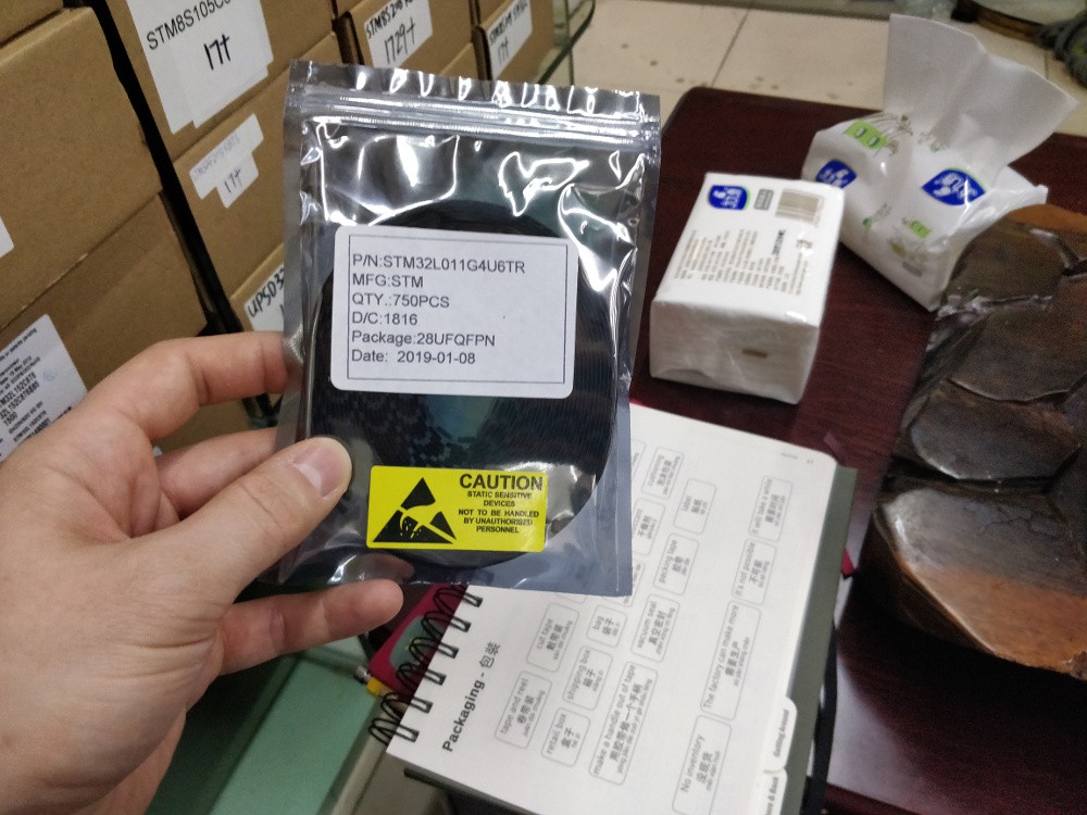
When we came back later that week with an even larger stack of yuan, the transaction was easy. I wasn't set up to test the microcontrollers, but I was able to visually inspect them and confirm the markings. Per bunnie's guide, the price was about what I expected, which gave me reason enough to trust the authenticity of the parts.
Our business done, the vendor invited us to their office a few blocks away for tea. I enjoyed the traditional tea routine generally, and was particularly fascinated by the automatic tea table (complete with auto-filling tea pot):
After going out to lunch with our new business associates, we parted ways for a final time, but not before exchanging WeChat scans.
Time to update the Project Details Section again. Saving the previous version here for posterity. Something something revision control readme.md etc
Thanks for checking out NeuroBytes!
This Project Details section is current as of 9/25/2017. To see the previous edition, follow this link.
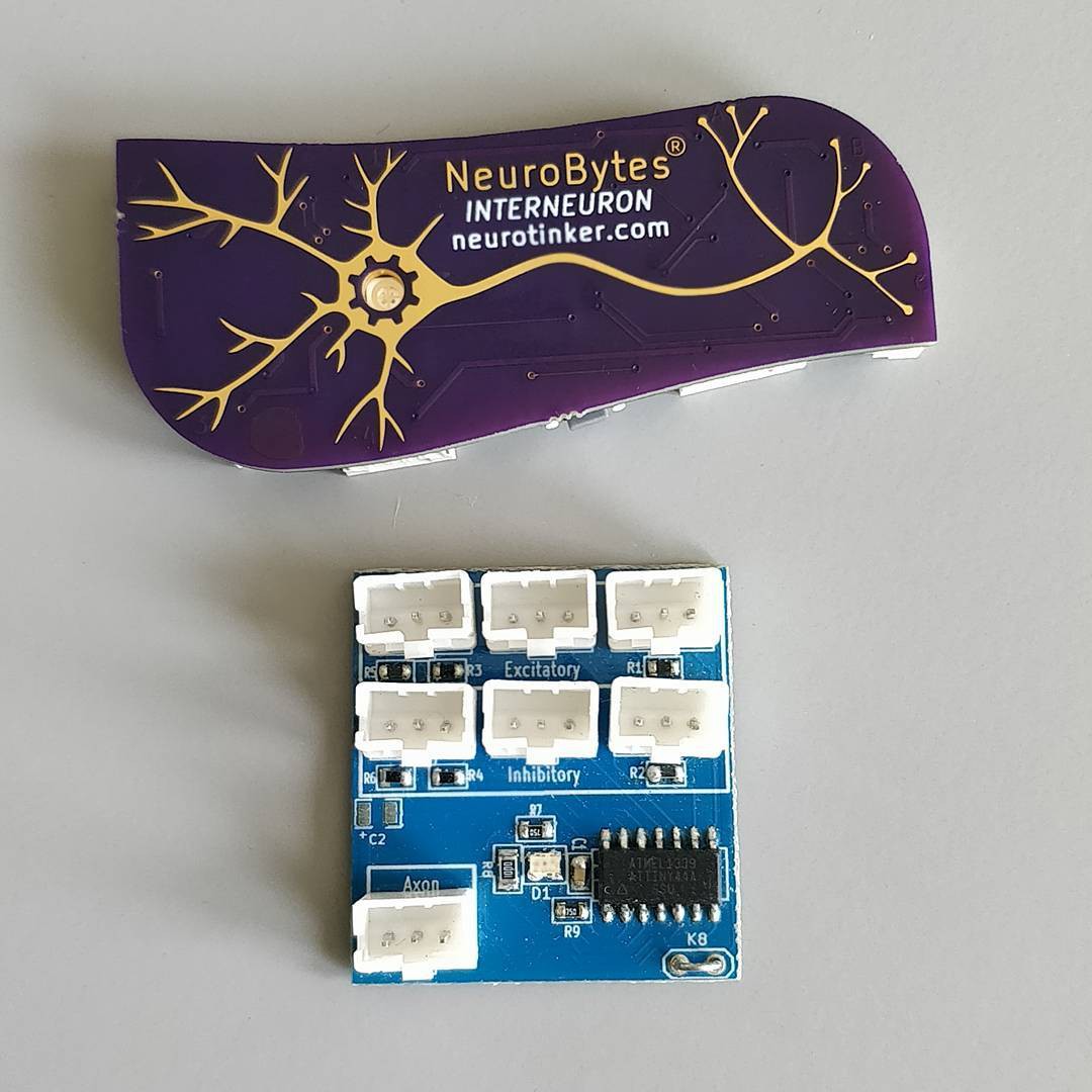
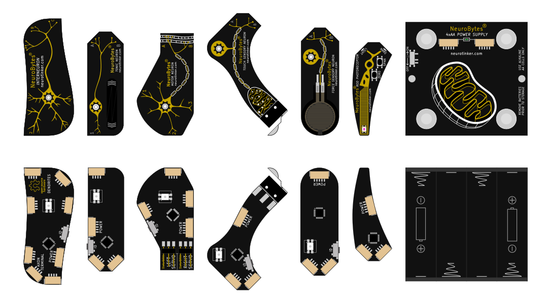
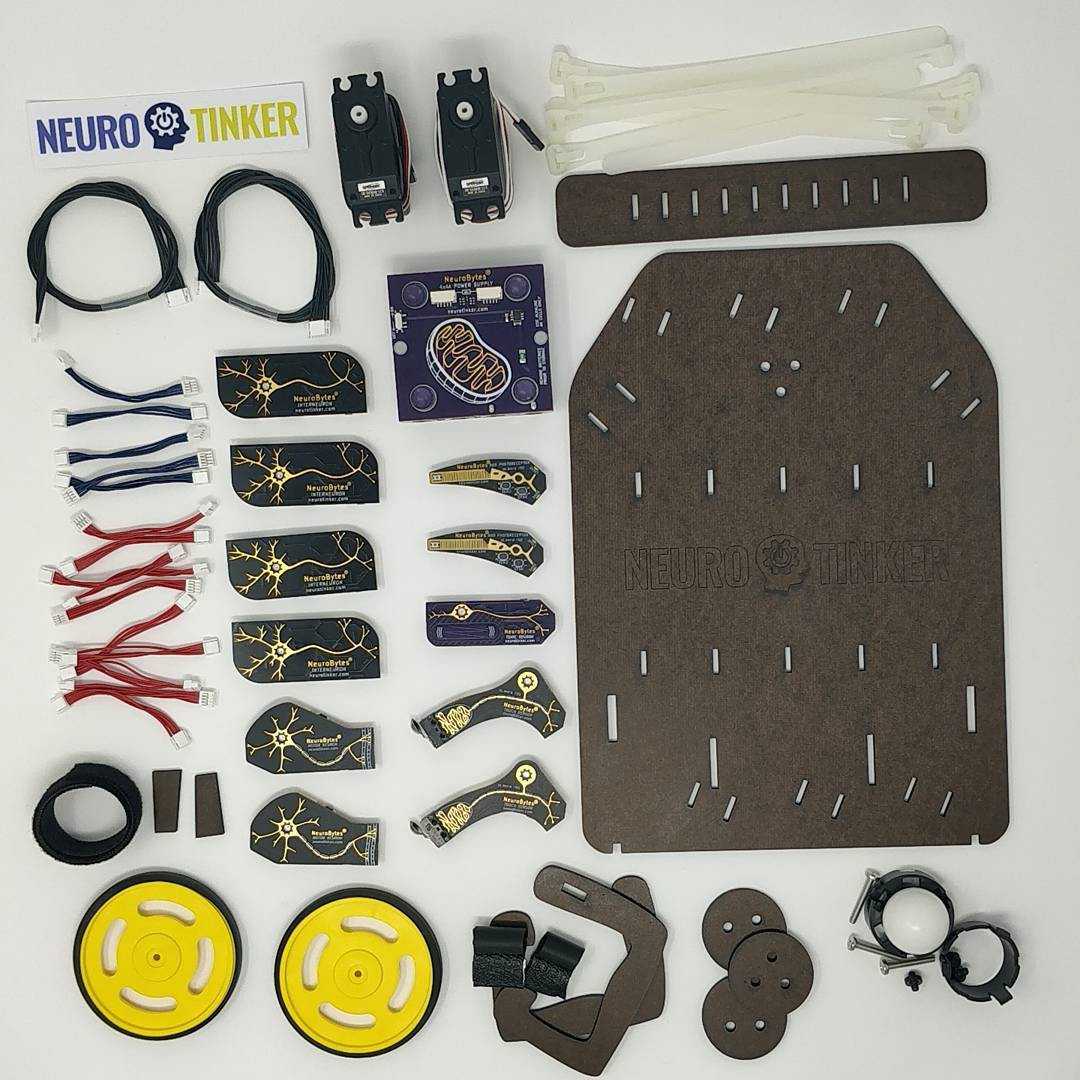
[Above: 3+ years of NeuroBytes evolution. The new boards have different connectors, different microcontrollers, different graphics, different LEDs, different communication protocols, and ... well, different just-about-everthing. Below: the current NeuroBytes ecosystem as rendered from the original PCB designs, all of which have been prototyped and some of which have been produced in 100+ board quantities. Left to Right: Interneuron, Tonic Neuron, Motor Neuron, Touch Sensory Neuron, Pressure Sensory Neuron, Rod Photoreceptor, Battery Pack. Not shown: Vestibular System, Cochlea, NID, Braitenberg Vehicle chassis, Patellar Reflex model, etc...]
NeuroBytes® are open-source electronic neuron simulators designed to help students understand basic neuroscience. Each module can be freely connected with others to form complex and biologically representative neural networks. On-board reverse-mounted RGB LEDs indicate current state: excited, inhibited, firing, learning, etc. The boards are based on the STM32L0 ARM Cortex M0+ microcontroller and the libopencm3 hardware library, and communicate via a novel board-to-board networking protocol that allows central data collection and global message broadcasting.
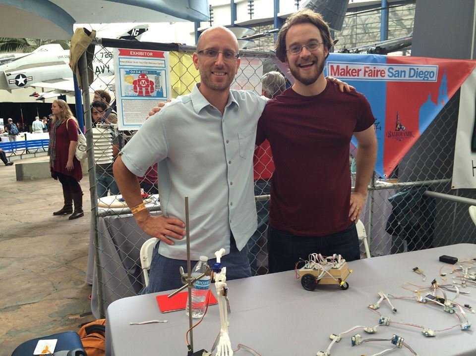
[img: NeuroTinker co-founders Joe (left) and Zach (right) at San Diego Maker Faire 2015]
Since its inception in mid-2012 and hardware development starting in February of 2014, this project has gone through many iterations and spawned the formation of NeuroTinker, LLC, a for-profit company primarily funded via Phase I and Phase II SBIR grants from the National Science Foundation. We are currently on track to commercially launch the product via a crowdfunding campaign before the end of 2017, and will have products for sale on the general market in early 2018.
NeuroBytes GitHub Repository. The firmware and hardware files for this project are released under GPLv3 and the latest version will always live in the linked GitHub organization. Individual boards are listed under their respective names (Interneuron, Motor Neuron, etc).
NeuroTinker company site. This is where we share additional information related to the NeuroBytes product line, such as operating instructions, kit purchase links, and social media account info. We have a public forum on the site that sees occasional use, and a spot to sign up for infrequent email newsletters that make every effort to consolidate important info into one location.
This project page. Yes, the project page you are currently reading. New project logs will appear somewhat frequently and tend to provide a good up-to-the-minute record of technical challenges and developments; conversely, if you want an exhaustive history of NeuroBytes you can start at the beginning. We've had a few great conversations in the log page comment sections (along with the main comment section), so don't hesitate to provide your input.
[img: jumbo-sized and functional NeuroBytes v0.91 board built for World Maker Faire 2016.]
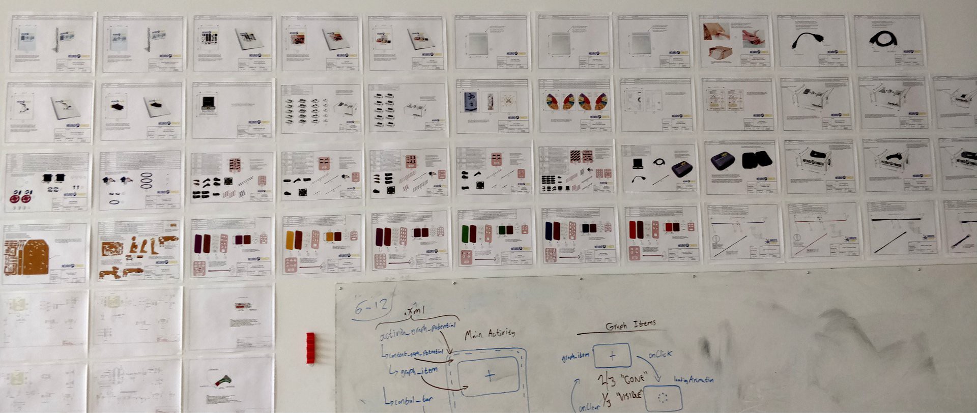
Above: Over the past few months I started putting production prints and assembly instructions on my wall as a way of keeping track of progress. It got a bit out of hand but was quite satisfying to see.
Last week, after many months of back-and-forth with our NeuroBytes manufacturing partner, I issued the production purchase order and wired a bundle of cash to kick off our first real run. We are making 4,285 STM32L0-powered NeuroBytes boards, along with 475 Battery Packs and 130 Network Interface Devices. The factory is also building 6,600 cable assemblies and sourcing servos, laser cut wood parts, packaging trays, manuals, and much more to produce 525 complete NeuroBytes kits. I am excited that this number represents five times our Kickstarter commitment, meaning we will have plenty of kits left to fulfill other pre-orders we have received since the close of our campaign and put a bunch of kits into inventory. There is still much that could go wrong, but NeuroBytes are much closer to becoming a Thing You Can Buy (If You Want).
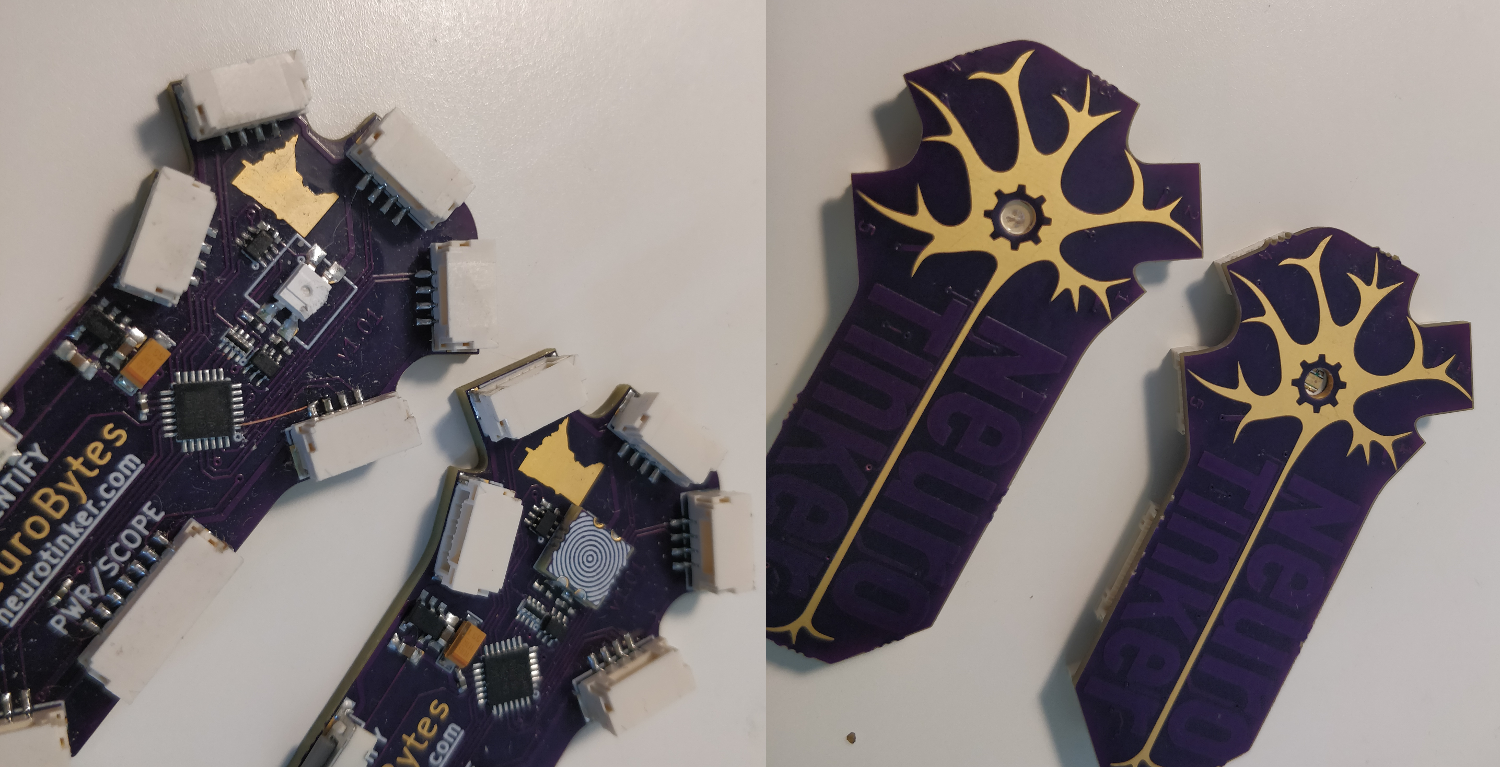
@Davor recently posted a request for an alternative to the SunLED reverse-mount RGB LED we used on nearly all NeuroBytes boards. @Jarod White actually had the same thought when he first joined the company, and I created a 6mm x 6mm castellated daughterboard that allows one to reverse-mount a common-anode 0606 RGB LED (I used the LTST-C19HE1WT from Lite-On) in place of the specified device. I had to dig this one out of the archive; I only tested it on an old-logo-design ARM prototype:
The boards look a bit different but the LED effect is the same. And I included a sweet concentric circle silkscreen pattern on the back for good measure. I think I did forget a polarity alignment mark though.
Design files for the daughterboard (KiCad and Gerbers) are in the Files section. Uploading the design kicks back an error on OSHpark as the boards are just below 0.25" x 0.25", but it's simple enough to pattern the design in KiCad so several are fabricated at once. And now that the SunLED devices appear to be out of stock (at least on Digi-Key), this design may become ever more relevant.
... and other cool stuff @Jarod White came up with but hasn't had time to talk about. Sorry to jump the gun, friend, but feel free to comment if you have anything to add.
Revisiting the Oscilloscope
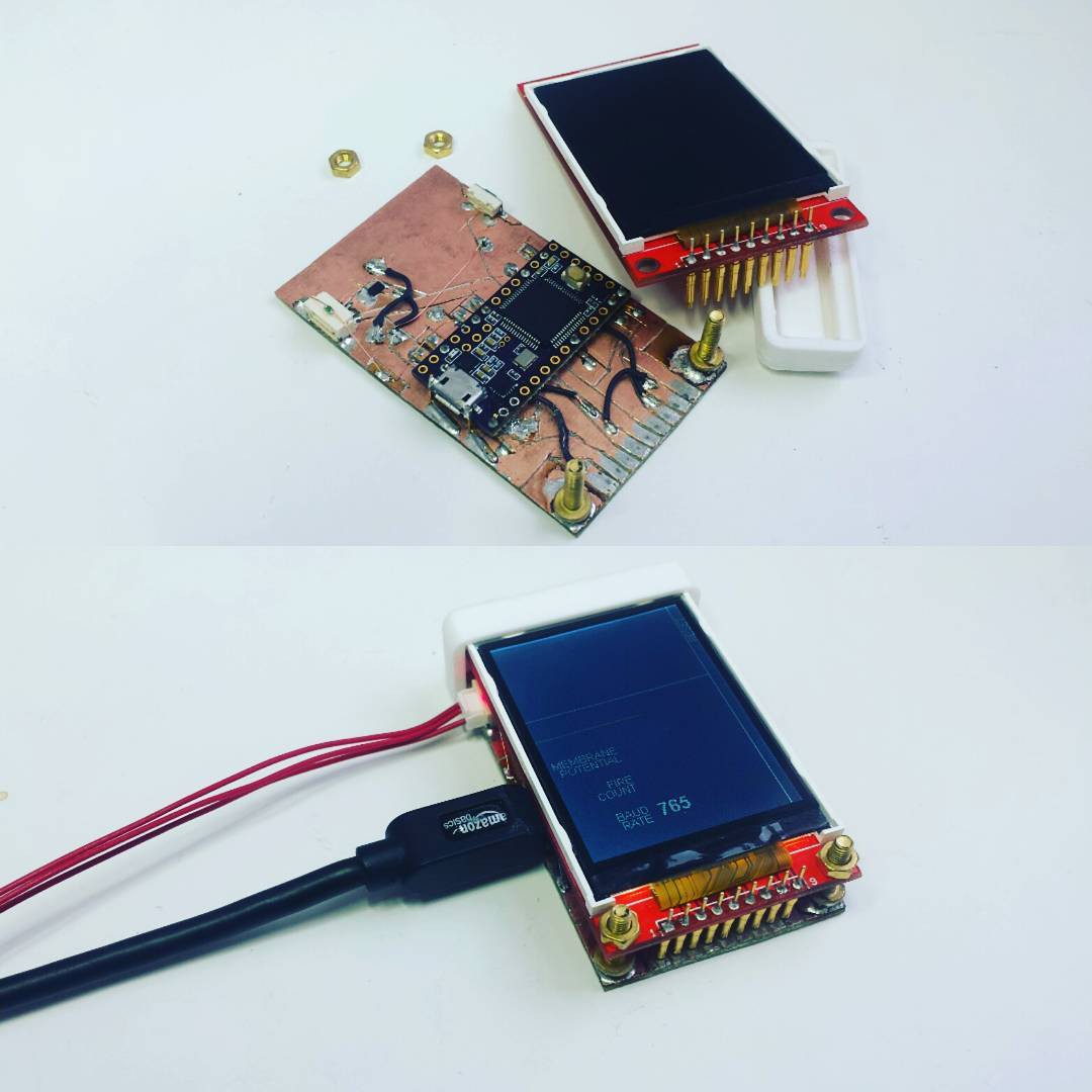
Sometime in early 2016, I created the NeuroBytes Oscilloscope, a prototype device that allowed one to view the real-time membrane potential of a connected NeuroBytes board:
I built two Oscilloscopes, one for me (below) and one for @NeuroJoe (above). The devices, based around the #Teensy 3.0 & 3.1 & 3.2 & 3.5 & 3.6 with a portrait-style 320x240 LCD, worked with ATtiny88-based NeuroBytes v0.8. The boards ran modified firmware that bitbanged UART data via one of the dendrite connections. Note the baud rate indication on the LCD in the image above; the bit-banging wasn't carefully clocked, so I tweaked the Teensy's UART speed to get good data (in this case, at 765 baud).
We didn't anticipate the reception we would get showing these devices to potential customers. At Maker Faires, on college campuses, and in high school classrooms, the consensus came in that this was our missing piece. Viewing real-time membrane potential allowed the user to fully grasp the meaning of the LED color on each NeuroBytes board. Students immediately grasped concepts like temporal and spacial summation, dendritic weighting, action potential thresholds... the list went on. The Oscilloscope had the makings of the NeuroBytes 'killer app'.
Platform Change
After NeuroBytes v0.91 (the green boards), we decided to change microcontroller platforms from the ATtiny88 to the STM32L0. Part of this was performance-driven; our decay algorithm at the time made use of 16-bit variables on an 8-bit micro, something that could cause issues with our use of pin-change interrupts if we weren't careful. And the ATtiny88 lacked three independent timer outputs, meaning the RGB LED had to be PWM'd manually. This led to all sorts of code optimization tangents that never really eliminated LED flicker and significantly limited algorithm complexity.
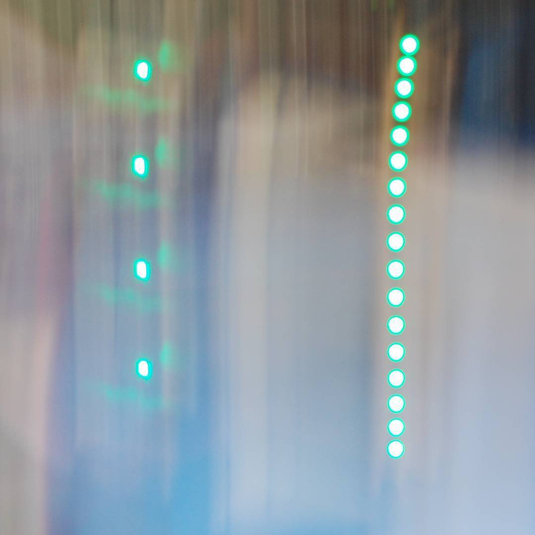
[above, swinging a long-exposure camera at NeuroBytes v0.4 (left) and v0.8 (right). Flicker got better, but 160 Hz still ain't good enough for an RGB LED running at 10% brightness.]
Mostly, the decision to switch microcontroller platforms was driven by cost. Say what you will about the Microchip acquisition of Atmel; all I know is that around that time, ATtiny88 prices doubled and suddenly the 32-bit L0 was the budget option. Goodbye avrdude, hello st-link and libopencm3.
When I designed the first NeuroBytes boards based around this new processor, I wanted to build in oscilloscope functionality from the start. I also wanted to ditch pogo connections for programming so end users could more easily reflash boards. And we wanted a dedicated and unique (i.e. not 4-pin) power connection for each board -- students were getting confused by the notion of plugging a battery pack into an axon or a dendrite ("but I thought neurons were unidirectional, why does the power connection not matter... ?"). In any case, I added on a 7-pin JST GH connector for power, programming, and a dedicated SPI port for the 'scope:
We eventually ran into issues with the 7-pin JST GH connector; the plastic webbing on the top of the connector spanned far enough that it was easy to damage. The clear answer was to ditch the SPI NSS and MOSI lines and move to a 5-pin connector.
Jarod has an idea
The new oscilloscope concept, as I planned it at least (with 4 channels), would have worked something like this:
Black wires are 'scope data, red cables are NeuroBytes impulses. Problem: cables are expensive and tend to get out of control when you have a lot of them in a small space. Jarod thought we could do it like this: The NeuroBytes would send data along the same cables as they originally sent simple pulses to indicate action potentials. Inter-neuron communication! Data packets! Routing! Loops! Gah! I told him to prove he could get it to work, and in the meantime I kept the SPI port exposed as a backup.
JARONET
He got it to work. I started calling the inter-neuron communication protocol JARONET, but eventually we started saying 'NeuroBytes Comms' or 'interneuronal communication protocol'. But I wanted to say 'JARONET' one last time, so.. here it is. JARONET.
We spoke with a great number of smart people about this problem and were frequently told to use a standard peripheral and an established protocol; I2C came up a lot due to its ubiquity. However, the NeuroBytes use case presents a few challenges to this plan:
Some of our boards, such as the Interneuron, include 7 individual connections that are all intended to be used simultaneously. We'd need a microcontroller with an on-board peripheral multiplexer or one with sufficient channels to cover all dendrites and axons, or we'd need to bit-bang everything. More on that shortly.
We simulate neurotransmitters using cables and distinguish between excitatory (red) and inhibitory (blue) connections. These cables can be wired differently, but they have to use the same connectors and don't have any active components. NeuroBytes v0.8 and v0.91 simply added a fourth signal wire to indicate inhibitory pulses; if both lines went high, the downstream NeuroBytes board knew to decrease its membrane potential. In other words: the protocol needed to handle straight-through and crossed data lines, and adapt to both cases on the fly since the network can be freely reconfigured at any time.
Data needs to go both directions. The Oscilloscope (later the NID, or Network Interface Device) could be connected to a sensory neuron at one end of the network or an Interneuron in the middle; in both cases, the user needed to be able to get data out of any board on the network. So while the v0.4, v0.8, and v0.91 NeuroBytes were unidirectional (i.e. the dendrite pins were always configured as inputs), the new boards would need to be flexible depending on neurotransmitter cable type and location on the network.
The solution was a low-speed bit-banged communication protocol based around pin-change interrupts and multi-part variable-length messages. All of the communications bits live in the NeuroBytes_Common GitHub repo, since they're shared among all boards. Jarod has done a great job documenting the various messages so I'll reproduce his comments verbatim:
/*
    This and comm.c define all communication protocol using the NeuroBytes
    protocol specification.

    All packets are between 4 and 32 bits in length and begin with 1-bit high
    and a 3-bit message header:
    [1-bit high] [3-bit header]
    The message headers are:
    0b000  -   Unused
    0b001  -   Blink (Debug)
    0b010  -   Data to NID
    0b011  -   Downstream Ping
    0b100  -   NID Global Command
    0b101  -   NID Selected Command
    0b110  -   NID Ping
    0b111  -   Downstream Pulse
    There are three types of communication that are supported in this protocol:

    1.  Network Interface Device (NID) broadcasting to all neurons in the
        network.
        Messages are sent by NID and received by all devices on the network.
        Global Commands are processed by every device on the network.
        Selected Commands are processed only by the device with the channel
        specified by the message.

        Included message headers:
        0b001 - Blink
        0b100 - NID Global Command - Send a command to the entire network
        0b101 - NID Selected Command - Send a command to a previously selected device
        0b110 - NID Ping - Propogate ping in order to update NID route

        ####### NID Global Command ########
        NID Global Command structure:
        [1-bit high]
        [3-bit header]
        [6-bit command]             - See list of global commands below
        [More depending on command]
        Global Commands:
        0b001 - Identify. Followed with 3-bit channel
        0b010 - Version. Followed by 16-bit board id and version number. Used to blink out-of-date boards.
        0b011 - Pause.
        0b100 - Play.
        0b101 - Zero
        0b111 - Span
            *Note: 6-bits is probably excessive for global commands. Might change in the future.
        Example NID Global Command:
        Identify new neuron on channel 2.
        1           [1-bit high]
        100         [NID Global Command Header]
        000001      [Identify Command]
        010         [Channel 2]
        _______
        = 0b1100000001010

        ######## NID Selected Command ########
        NID Selected Command:
        Used to either send a command to a specific neuron (e.g. go into
        learning mode) or change the value of an operating parameter
        (e.g. set dendrite 1 to 120%)
        NID Selected Command Structure:
        [1-bit high]
        [3-bit header]      - always NID Selected Command Header (0b101)
        [3-bit channel]
        [1-bit change parameter flag]
        [4-bit command] OR [4-bit parameter ID] - depending on if [change
            paramater flag] is set
        (optional) [16-bit data]
        NOTE: Parameter IDs are board-specific (i.e. different for every board).
        They are not all fully specified yet. Currently Interneurons and
        Motor Neurons are set.
        Their values can be found in their repos (main.c).

        Example NID Selected Command:
        Set the value of dendrite 1 on an interneuron on channel 4 to 256
        1                   [1-bit high]
        101                 [NID Selected Command Header]
        100                 [Channel 4]
        1                   [Change Parameter]
        0010                [Dendrite 1] *Parameter IDs can be found in main.c for each board (NOT FINAL)
        0000001000000000    [Change to 256]
        ________________
        = 0b1101100100100000001000000000

        ######## NID Ping ########
        Functional Summary:
        NID pings are periodically sent (~200 ms) by NID to the whole network
        in order to update the shortest-route-to-NID memorized by every device.
        The NID ping packet contains a 6-bit distance field which is
        incremented by every successive neuron. The shortest route is
        determined by every neuron to be through the dendrite/axon that
        receives the NID ping with the shortest distance value. Memorized NID
        connections are lost if a NID pin is not received within
        NID_PING_TIME (~1000 ms).

        NID Ping Message Structure:
        [1-bit high]
        [3-bit header]      - always NID Ping Header (0b110)
        [6-bit distance]
        NID Ping Example Message:
        NID Ping relayed by two neurons so far
        1           [1-bit high]
        110         [NID Ping Header]
        000010      [distance = 2]
        _______
        = 0b111000010

    2. Selected neurons sending data to the NID.
        Messages are sent by identified devices and are relayed along the
        shortest path to the NID. The shortest path to the NID is maintained
        by NID pings. Messages sent from identified devices to the NID.
        Capable of sending many different types of data (16-bits) to the NID.
        Included message header:
        0b010 - Data to NID

        ######## Data to NID #######
        Data message structure:
        [1-bit high]
        [3-bit header]              - 0b010 (Data Header)
        [3-bit subheader]           - specifies type of data being transmitted
        [3-bit channel]             - specifies channel sending the data
        [1-bit fire flag]           - flag indicating the neuron fired
        [4-bit parameter id]        - (optional) further specifies the type of
            data (e.g. dendrite weighting number)
        [16-bit data]
        Subheaders:
        0b000   - membrane potential
        0b001   - board type
        0b010   - unique id
        0b011   - operating mode
        0b100   - board-specific parameter
        At this time, board-specific parameters (for Parameter ID) have not
        been fully assigned. But some values can be found in their respective
        firmware repos in main.c

        Example Data Message:
        Data message from an interneuron on channel 3 sending its membrane potential:
        0b[1][010][000][011][0][0000][0000001101011100]
        Motor neuron on channel 1 sending dendrite 1 value of 2048
        1                   [1-bit High]
        010                 [Data Header]
        100                 [board-specific parameter]
        001                 [channel 1]
        0                   [fire flag 0]
        0100                [Dendrite 1 Parameter ID]   *see motor neuron repo for Parameter IDS (NOT FINAL)
        0000100000000000    [dendrite 1 = 2048]

    3. Upstream neurons sending pulses to downstream neurons (axon -> dendrite).
        All neuron->neuron communications are maintained by the downstream
        ping which distinguishes excitatory and inhibitory connections.
        Only two messages sent in this category:
        0b1011 - Downstream ping message
        0b1111 - Downstream pulse message
*/
There are messages that establish optimal routing from each NeuroBytes board back to the NID; there are messages that identify which type of neurotransmitter cables connect boards; there are messages that simply send action potentials to downstream NeuroBytes (which in previous generations were 5V 200ms blips); there are messages that reconfigure parameters on a given board; there are membrane potential messages; and there are many more functions we have planned for the future. As of today, the protocol is extensively tested, extremely robust, and gives us a ton of bandwidth for future expansion. On an arbitrary 20-NB network, we can easily pull 20 update/second membrane potential data out four random NeuroBytes boards without any detriment to standard network functionality (i.e. normal action potentials, etc). And we've tested higher data rates and higher simultaneous channel counts without issue.
More to come.
This post is long enough so I'll dedicate a future update to NID functionality and the companion tools (Android app and Linux command line interface) that allow user interaction.
First some good news: we made our Kickstarter goal by a comfortable margin ($34k of a $25k target). Thank you to all of our supporters, especially those whom found us via the timely Hackaday blog post. We aren't immediately cutting a PO to manufacture the products (for reasons I cover below), but our plan is to do a ~$50k manufacturing run -- in other words, if you missed the KS campaign we'll have tons of inventory left to sell. And we're fortunate that we don't need Kickstarter money to pay our salaries or cover the costs of testing. We are lucky -- most don't have that luxury.
Earlier this month, Jarod and I spent the day at a local compliance testing facility. Our products -- the NID, the battery pack, and all the NeuroBytes boards -- don't have any intentional RF sources on board, so the radiated emissions testing under FCC 15.109(g):2018 and ICES-003:2016 is called 'unintentional radiator' testing. Before I discuss results, a few pictures from the 10m anechoic chamber:
above, the 10m anechoic chamber entrance. Of note: the inner door handle is plastic. You can also see the low-frequency antenna mounted on its automated rising boom. This test is a farfield measurement, so the antenna is 10m from the target and measurements are taken with horizontal and vertical polarities from a variety of heights.
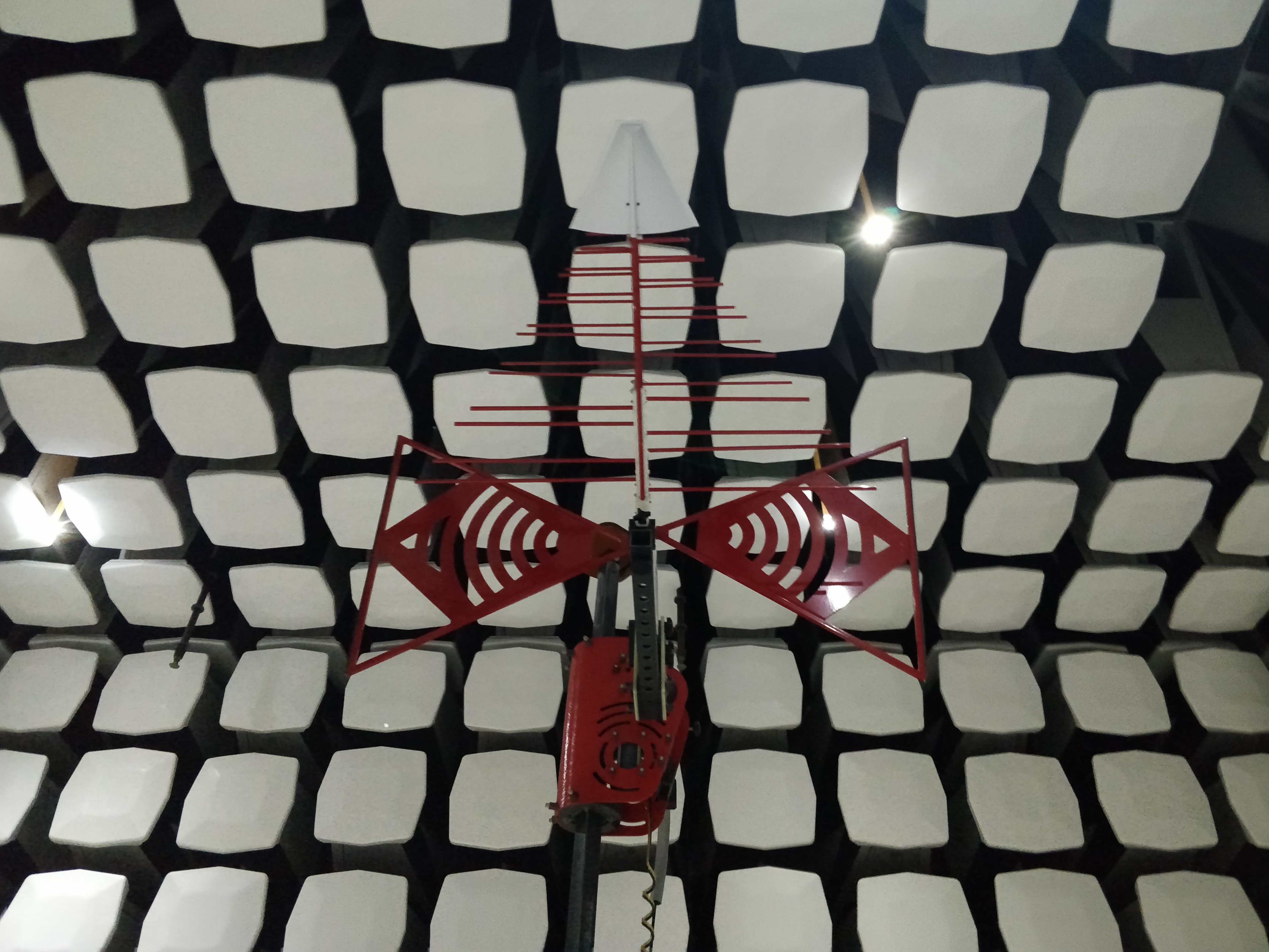
above, a close-up of the low-frequency antenna. Note the bizarre conductive foam anechoic panels (they are probably 600mm square and extend back into the wall 1m), and the expensive fiber-optic lights.
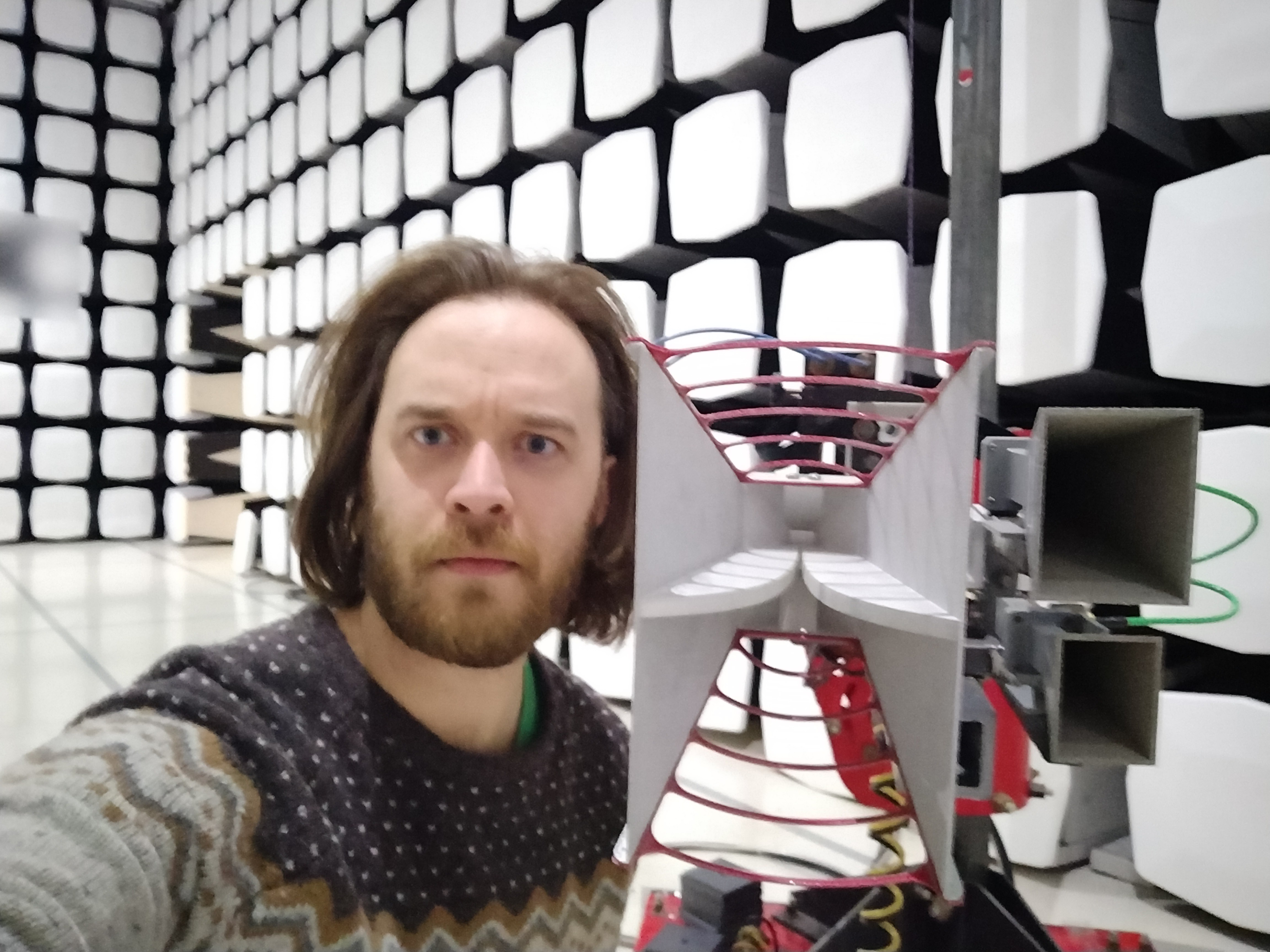
above, obligatory high-frequency antenna selfie. We didn't use this one since our equipment didn't have any active radiators (so we swept up to 1 GHz).
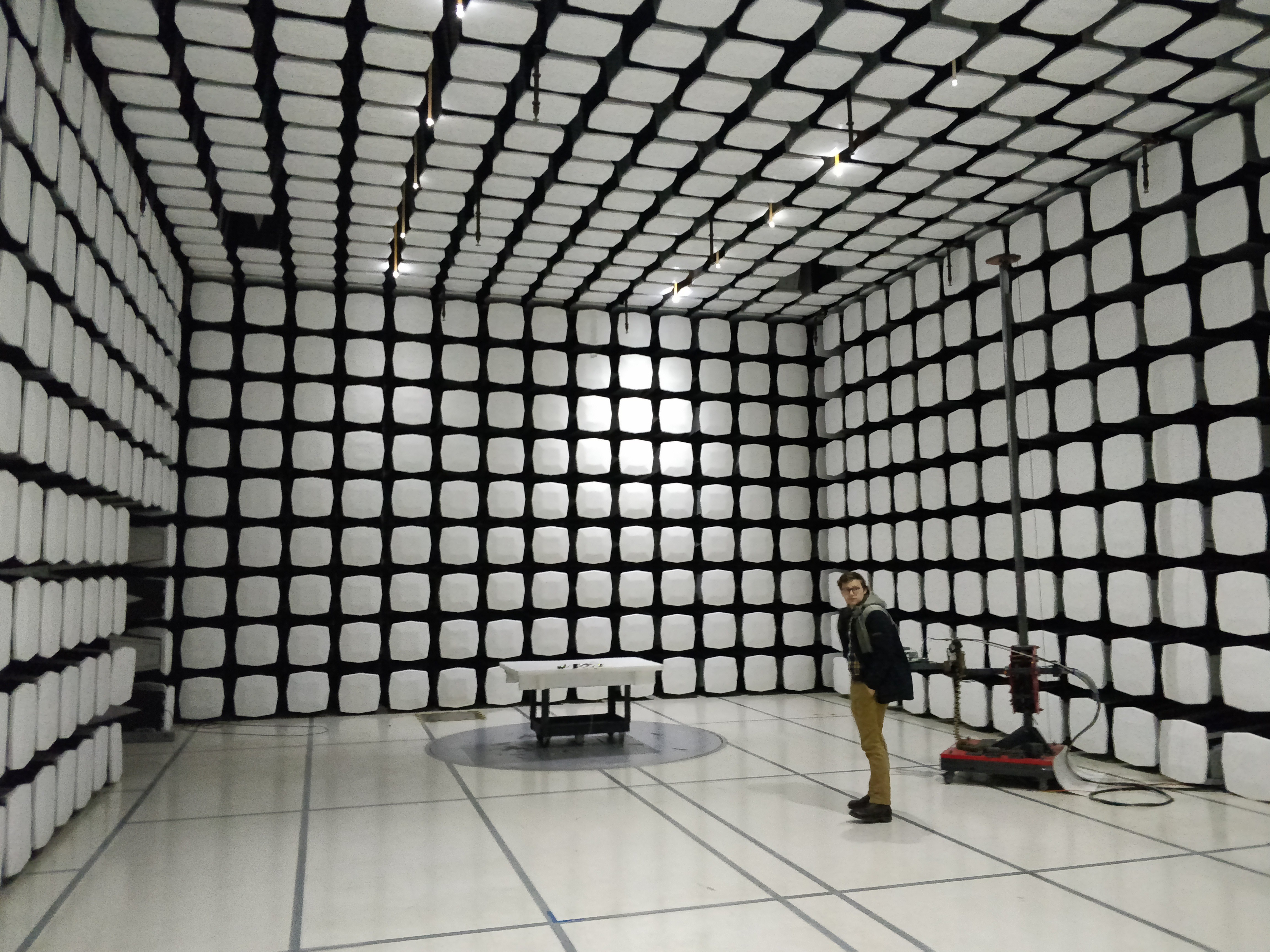
above, Jarod stands by the high frequency antenna. The table on the round floor piece holds the NeuroBytes network (barely visible) and rotates continuously during testing. We stashed the NID's tablet in the floor so it (hopefully) wouldn't interfere with results.
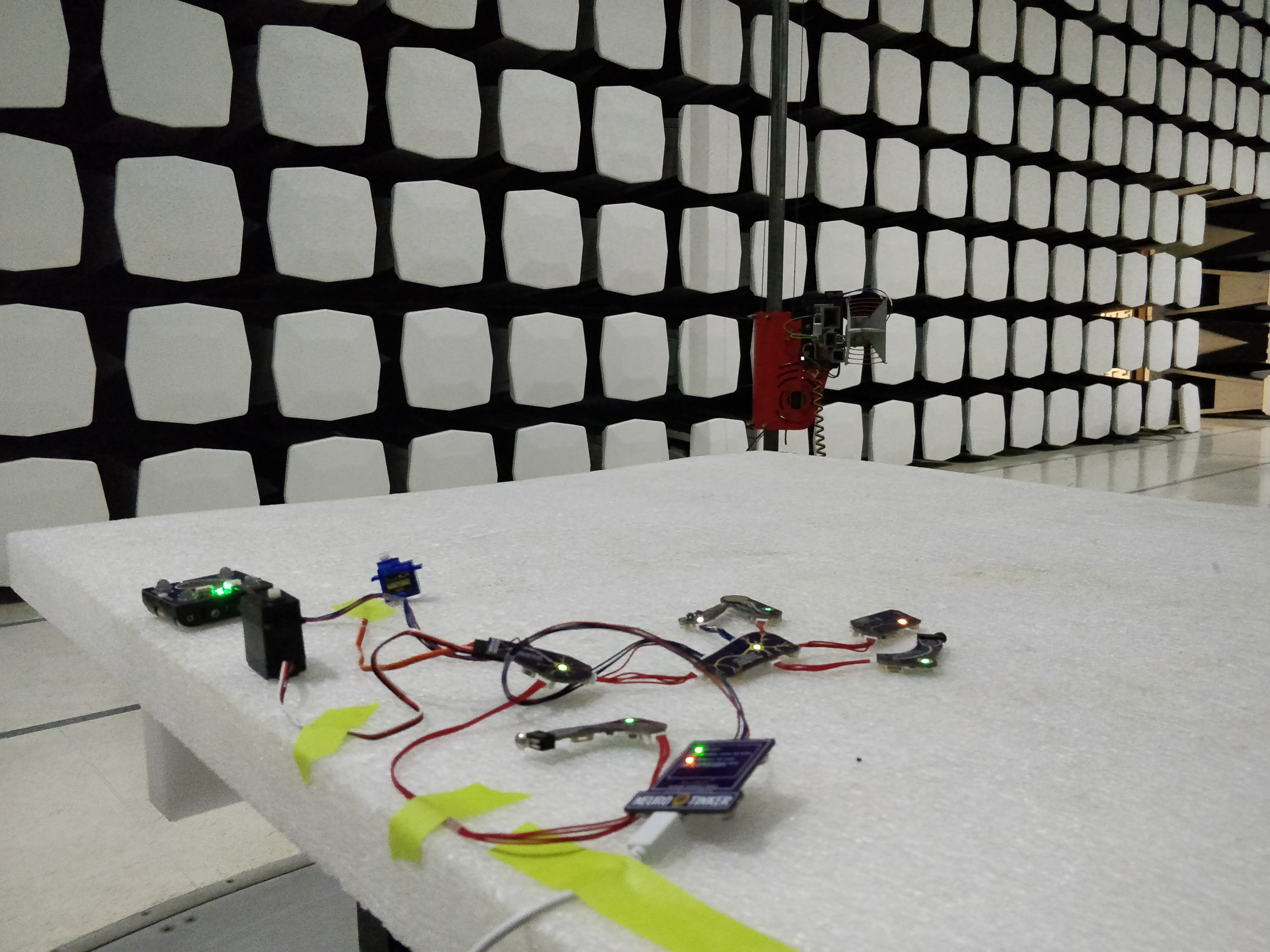
above, our chosen NeuroBytes network configuration for compliance testing. After consulting with the lab and a number of other sources we determined that a representative network with a 'typical' amount of traffic would suffice; testing boards individually would be cost prohibitive and, more importantly, not representative of how NeuroBytes are actually used.
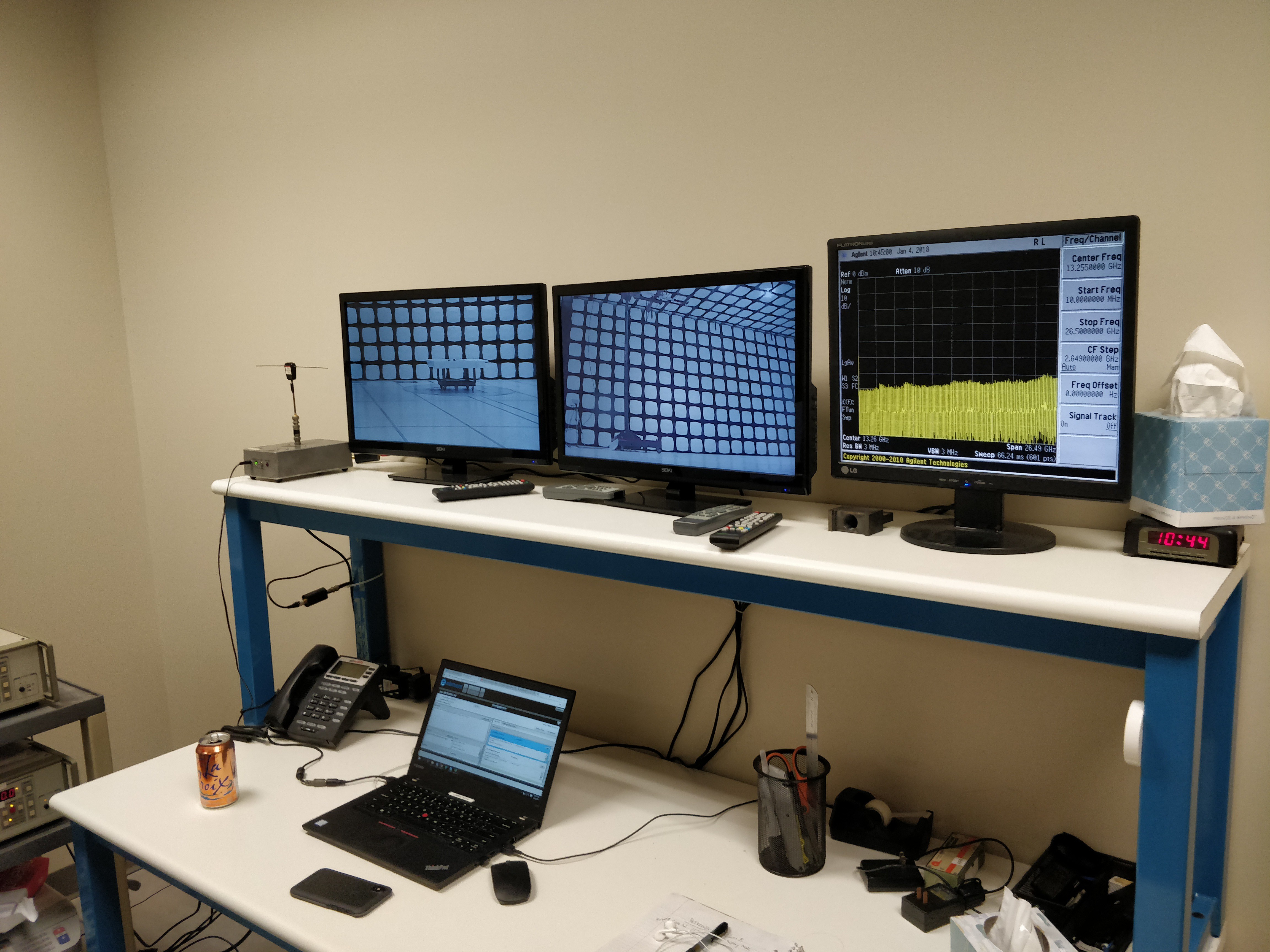
above, part of the analysis setup at the lab -- several shielded cameras recording the DUT (Device Under Test) along with a screen from their insanely fancy Agilent spectrum analyzer (whose model number I forgot to jot down).
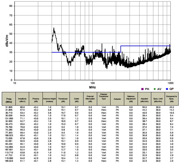
Yeah, it was a neat experience, and the tech who worked with us for the 2-hour radiated emissions test was helpful and well-informed. Then we failed the test! Results:Above, a full NeuroBytes network test with the NID attached and the tablet graphing real-time data. This graph shows raw cumulative test data and we didn't actually fail in all the spots shown; after running through the quasi-peak detector we found that the first big hump (~30 MHz - 40 MHz) is the one we need to worry about.
We got the result above after a ~10 minute test, so we had plenty of time to try various experiments to narrow down the problem. I was concerned with rise time on the inter-neuron communication lines causing EMI spikes; our tech thought the USB cable may have been the issue. We didn't have any better-shielded or ferrite-equipped cables with us, so he tried snapping a giant 'suitcase ferrite' onto the USB cable:
Above, maybe we're on the right track going after the USB cable? The 32 MHz peak is down quite a bit, but the 39 MHz peak jumped a few dBuV/m...
Not shown here, we also tried pulling both the continuous rotation servo and the micro-servo off the network; even though they're tiny I thought we might be seeing some commutation noise. No change.
Next, we ditched the tablet and USB cable entirely. Unfortunately this meant we didn't have data running between the NID and the first NeuroBytes board, but we wanted to be sure the emissions weren't coming from the inter-NB connections: Above, bingo! The two peaks around ~110 MHz wouldn't cause a failure after quasi-peak detection so we're in the clear for a NB-only network.
Finally, as the end of the second hour approached, we ran a test with _just_ the tablet and NID. And we got some very strange results: We didn't have time to do anything else, but I'm inclined to think that we were picking up excess EMI from the tablet itself; during testing it sat under the floor but the shielding had a fairly substantial (~150mm) hole, and the USB cable we brought was only 1m long. This wasn't our best day, but I think we learned a lot. For starters, we verified that NeuroBytes on their own are good to go with respect to EMI -- all the issues we encountered had to do with the USB communications between the NID and the tablet (with the aforementioned caveat regarding NID-->NeuroBytes comms not being independently tested). When we initially planned for EMI testing we considered doing some pre-tests, either in-house or at a lab, but decided to take a chance that we could pass based on extensive research and discussions with numerous more experienced engineers. It's probably a risk I would take again; re-creating EMI testing conditions in the lab is difficult and expensive, and pre-testing certainly doesn't come cheap either.
Having said that, our plan going forward has a few parts. First, we're going to recreate the results above in our lab, using a spectrum analyzer, a small test chamber, and a handful of hand-held nearfield probes. While these tests won't give us absolute data, we do have a few relative measurements (i.e. with USB and without) to compare to, so we should be able to see if any fixes we implement get us in the right ballpark.
Second, I bought a bunch of USB cables. Some are nicely shielded. Some have ferrites. All are longer than 1m, so when we go back for testing we'll be able to make sure the tablet is deep in the shielded floor area.
Third, we're going to play around with a few design elements -- improving ground planes where possible, adding ferrites and filter caps where needed, etc.
Fourth, we're going to do everything we can from a firmware perspective to increase rise times and eliminate high-frequency elements on the boards. Unfortunately we don't have a great deal of flexibility on the USB side (as it needs to be full-speed 12 Mbps for reasons I'll cover later), but we do have options.
And fifth -- I'd love to hear some ideas from you, dearest reader. Especially if you've been through radiated emissions testing and have thoughts about DIY testing. While we had the budget to re-test once, I have no intention of re-testing twice -- that means when we schedule our next visit to the lab, it should be the last.
Yes, the day is here. We've worked on this project for damn near 5 years (well, 3 years that are documented here, at least) and it's finally time to see if anyone actually wants to buy NeuroBytes. If you have kept up with my logs, hopefully you're confident in our ability to deliver products in a timely manner; we've sorted through the manufacturing side of things and when push comes to shove, our products really aren't all that complicated. I should also be clear about our goals: we want to get our products into the hands of real paying customers that will get angry and break things, and plow as much profit as possible into building inventory so we can make a big splash at NSTA's national meeting next year.
I guess I don't really expect a lot of Hackaday.io readers to be interested in actually backing our campaign -- I didn't start publishing logs here with that intent! In fact, if you're interested in NeuroBytes, I hope you head to our Github repo ( https://www.github.com/neurotinker ), grab our KiCad files, and spin up your own boards. Really, the QFNs are easy to solder by hand since they don't have ground pads.
However, if you have parents, relatives, students, or anyone else that you think might be interested in learning more about neuroscience in a hands-on way, I do ask that you pass our campaign on to them. Joe and I are new to this crowdfunding thing (and PR/marketing in general), so any help is appreciated!
[up next: less of this commercial spam and more interesting technical posts about things like our new Network Interface Device board, I promise]
[above, our NeuroBuggy Kit. Designed for building Braitenberg Vehicles and playing around with simple neural network-controlled robotics.]
Yes, the day is finally near at hand -- we're going to launch a Kickstarter campaign in the coming weeks to fund our first major production run. Joe and I (and Jarod, and Jill, and Andrew, and Pat, and Mel, and Cecilia, and a great many other people) have been working on this project for a number of years and it's time to push the concept into the real world.
We're starting with five kits; the NeuroBuggy Kit shown above, along with three physiology kits (the Knee Jerk Reflex Kit, the Eye Kit, and the Skin Kit), and one Advanced Kit that includes a whole bucket of NeuroBytes. We are also offering a few other reward options -- a sticker, a 'random board only', a standalone Network Interface Device, and two classroom-scale sets with curricula.
Expect at least one more log update pushing our KS campaign, but I'll also get back to the technical side soon enough. Jarod is getting close to a working NID prototype (I just ordered boards!), and its functionality is probably what has excited and driven us most in the past year.
So. If you are interested in following our KS launch, I suggest heading to the NeuroTinker website -- neurotinker.com -- and signing up for email updates on our page so you know when the campaign goes live. We're tentatively planning for 11/7, but... there are still many things to be done...
Time for another Project Details update. I guess these happen annually now? In any case, the previous text is below... this log mostly exists to preserve the 10/10/2016 copy:
Thanks for checking out NeuroBytes!
This Project Details section is current as of 10/10/2016. To see the previous edition, follow this link.
[img: NeuroBytes v0.91 boards getting programmed and tested, October 2016]
NeuroBytes® [we did register the name and the NeuroTinker logo, as discussed here] are open-source electronic neuron simulators designed to help students understand basic neuroscience. Each modular board includes five inputs (or dendrites) along with two outputs (its axon terminal) that allow easy connection with other identical boards. A rear-mounted RGB LED allows learners to quickly visualize various characteristics of each neuron, including membrane potential, operating mode, and firing rate. Additionally, analog sensors can be used for advanced biological modeling using our littleBits interface adapter and suitable analog input Bits (such as the light/dark sensor). Outputs can be connected to "muscles": 9g hobby servos driven through a NeuroBytes board switched to Motor Neuron mode.
[img: NeuroTinker co-founders Joe (left) and Zach (right) at San Diego Maker Faire 2015]
Since its inception in mid-2012 and hardware development starting in February of 2014, this project has gone through ten iterations and spawned the formation of NeuroTinker, LLC, a for-profit company primarily funded via a Phase I SBIR grant from the National Science Foundation. As of October 2016, we have submitted a Phase II application under the same prompt, joined an edtech-focused accelerator called EDSi, run a MN-based manufacturing trial that resulted in prototype sales into both secondary and post-secondary education markets, and generally spent a great deal of time preparing the products and accessories for commercial sale.
NeuroBytes GitHub Repository. The firmware and hardware files for this project are released under GPLv3 and the latest version will always live in the linked GitHub repo.
NeuroTinker company site. This is where we share additional information related to the NeuroBytes product line, such as operating instructions, kit purchase links, and social media account info. We have a public forum on the site that sees occasional use, and a spot to sign up for infrequent email newsletters that make every effort to consolidate important info into one location.
This project page. Yes, the project page you are currently reading. New project logs will appear somewhat frequently and tend to provide a good up-to-the-minute record of technical challenges and developments; conversely, if you want an exhaustive history of NeuroBytes you can start at the beginning. We've had a few great conversations in the log page comment sections (along with the main comment section), so don't hesitate to provide your input.
[img: jumbo-sized and functional NeuroBytes board built for World Maker Faire 2016.]
A few months ago, I mentioned that we were preparing to embark on a prototyping sprint. While prototyping will forever be a continuous and fluid process, at this point the fast-setting cement that is hardware development has solidified enough to share in a more formal manner than overly stylized Instagram posts:
In two(ish) months we are launching a crowdfunding campaign (I know... 'ugh'. Agreed. I promise to keep my project log spam to a minimum) with the following nearly finalized boards:
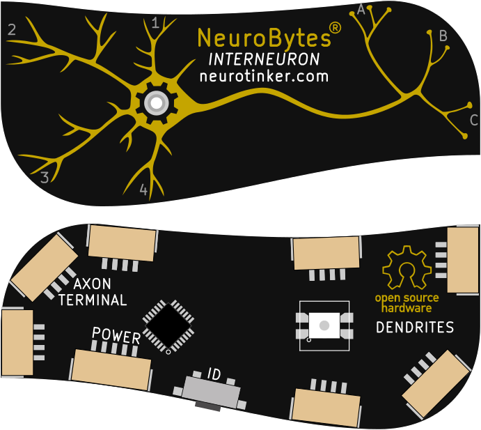
Interneuron
The Interneuron board operates as an integrate-and-fire neuron simulator, similar to the previous (v0.4, v0.8, v0.91, etc) NeuroBytes boards. Beyond the ARM upgrade (STM32L0 + libopencm3), these boards have a more balanced dendrite-to-axon ratio (4:3) which helps a great deal when building complex circuits. The graphics have changed quite a bit as well -- we're moving away from our previous logo-based design to something a bit more physiologically accurate, so the dendritic tree is quite a bit more spindly on this board. The learning mode features continue to grow more sophisticated; our latest iteration features potentiation and depression, both of which are triggered by switching modes with the on-board switch. And most importantly, these boards (along with the others in this post) no longer send simple voltage spikes to indicate a firing event; instead, they communicate via JarodNet, a novel protocol developed by @Jarod White that really deserves a post of its own.
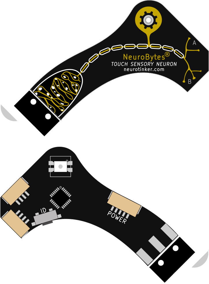
Touch Sensory Neuron
The Touch Sensory Neuron (previously Touch Sensor, previously^2 a tiny snap-action switch that attached to standard NeuroBytes) is pretty simple -- it fires immediately whenever the switch is pressed. From a pure cost perspective this board could be simplified a bit (or integrated with the Interneuron), but separating mechanoreceptors from interneurons is critical from a biology education point of view. The board graphics also show a few new concepts that can be taught in the classroom -- myelination (although this board doesn't operate any faster than others) and unipolar neuron physiology.
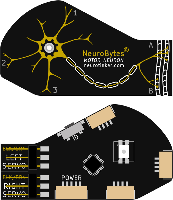
Motor Neuron
The Motor Neuron is currently the only output device (beyond on-board LEDs) in our ecosystem. Initially designed for our patellar reflex demonstration, the Motor Neuron is now also used to drive continuous rotation servos for building Braitenberg Vehicles (again, this deserves its own post). These boards have three equally-weighted dendrites and on-board connections for two servos, so we no longer need fussy and easy-to-lose JST-to-servo adapters. The ID switch is used to change between CR and STD servo mode.
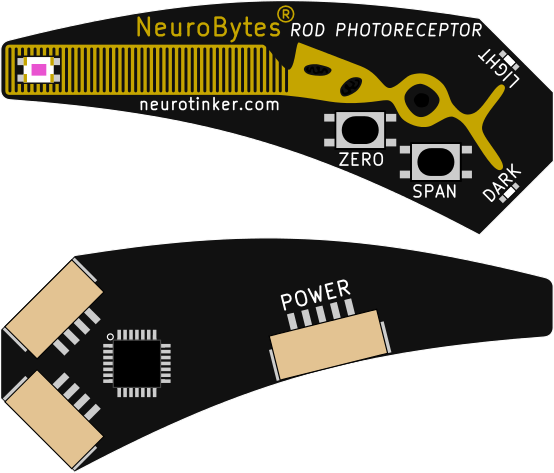
Rod Photoreceptor
The Rod Photoreceptor emulates its biological analogue by causing downstream NeuroBytes boards to fire at a rate inversely proportional to the light intensity at the sensor. In the interest of building more nifty circuits, we also provided a not-quite-biologically-accurate 'light output' that is directly proportional to light intensity. The boards use a Broadcom ambient light sensor, which is super slick because it integrates a photocell with a logarithmic-response amplifier circuit -- that means it responds to light like the human eye, and has the effect of giving us a few extra bits on the STM32L0's ADC. Crucially, the boards also have easy-to-use zero and span buttons so they can be quickly calibrated to ambient classroom conditions. And the top and bottom curves on the boards match up, so they can be stacked with the sensors quite close to each other:
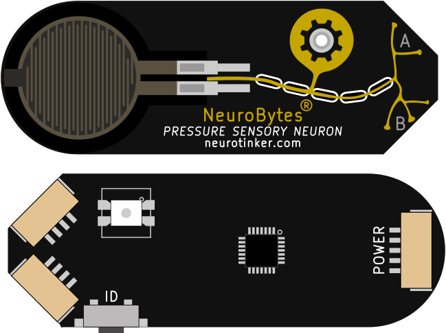
Pressure Sensory Neuron
The Pressure Sensory Neuron is another type of mechanoreceptor that fires action potentials at a rate proportionate to the pressure applied to the on-board force sensitive resistor. This is a great board for testing networks quickly, and it has quite a bit of range-ability -- the FSR combined with the STM32L0's 12-bit ADC mean a light touch and a hard press both produce noticeable changes. In the future we'll probably integrate some kind of adaptation mode so a constant pressure gradually decreases the action potential rate, just like in biology (this is why you stop noticing your shoes after a bit of time). This board is a bit more expensive than we'd like, mostly because the excellent FSRs are $5+ in 1000-lot quantities. Boo.
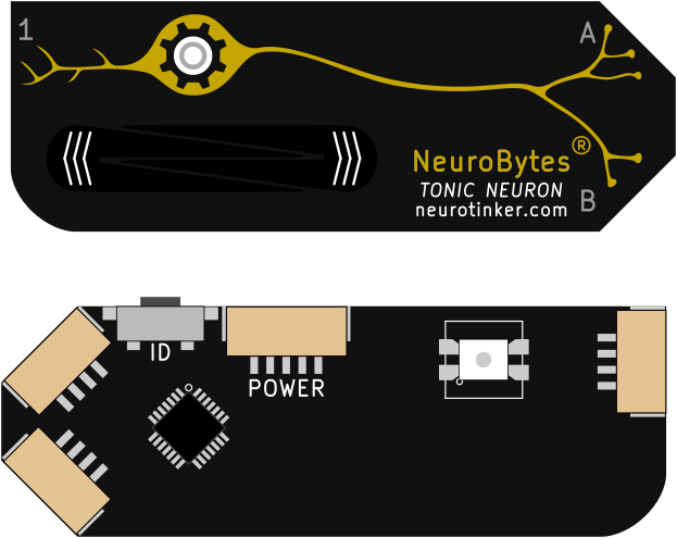
Tonic Neuron
The Tonic Neuron uses a linear touch slider (exhaustively detailed in a previous post) that allows the user to adjust the board's firing rate. Tonic neurons act as pacemakers, so you can inject arbitrary signals into the network and adjust (and hold) them quickly. The single dendrite connection means one can temporarily excite or inhibit the board, too. These boards run Patrick Yeon's excellent Izhikevich dynamics port, and will eventually give us the option to simulate more advanced neurons such as fast-bursting cells.
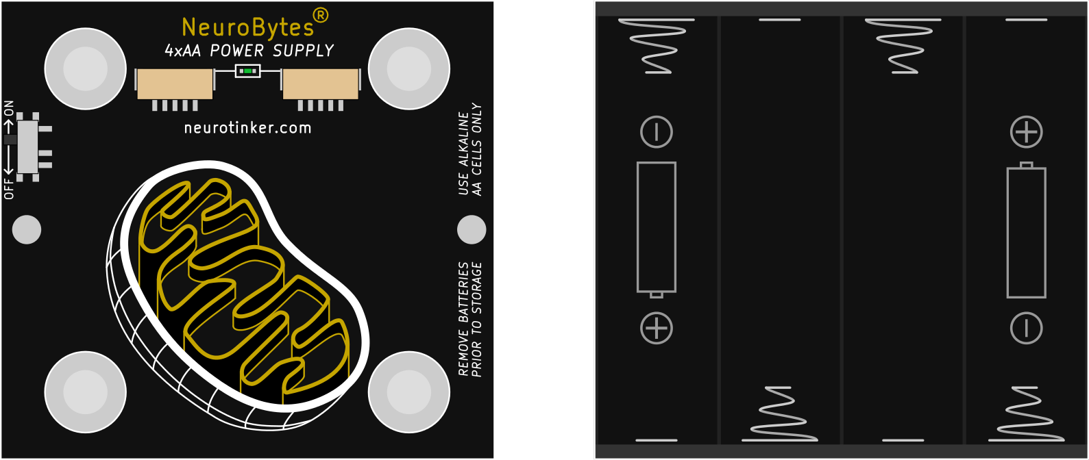
Battery Pack
The Battery Pack now uses a dedicated 5-pin connection (previously 7-pin, etc...) to provide power to NeuroBytes boards. We found that students got confused when we first told them to not connect NeuroBytes incorrectly (i.e. axon-to-axon), and then told them to attach the 4-pin battery cable to any port they wanted. More importantly, this allows us to break out the STM32L0's SWD contacts, making firmware updates a pogo-pin-free operation. The battery pack PCB is designed around a 4xAA PC pin pack I found on Digi-Key and includes a few polyurethane bumpers to protect the connectors. It uses a 5VDC LDO to output a stable 5VDC to the connected NeuroBytes. Yes, a buck converter is more efficient (and was prototyped), but EMI/FCC/simplicity/etc. And no, we aren't going to get into the business of shipping LiPo batteries.
That's it for now. The picture at the top of this post showed a few other awesome boards (the Vestibular System and Cochlea), and we're still working on the Network Interface Device that ties this together with the JarodNet platform. More to come, as usual..
 zakqwy
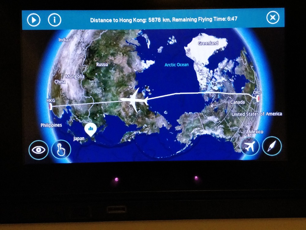


 The boards look a bit different but the LED effect is the same. And I included a sweet concentric circle silkscreen pattern on the back for good measure. I think I did forget a polarity alignment mark though.
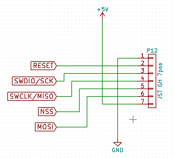 We eventually ran into issues with the 7-pin JST GH connector; the plastic webbing on the top of the connector spanned far enough that it was easy to damage. The clear answer was to ditch the SPI NSS and MOSI lines and move to a 5-pin connector.
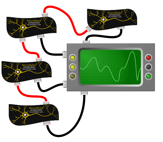 Black wires are 'scope data, red cables are NeuroBytes impulses. Problem: cables are expensive and tend to get out of control when you have a lot of them in a small space. Jarod thought we could do it like this:
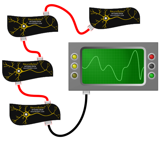 The NeuroBytes would send data along the same cables as they originally sent simple pulses to indicate action potentials. Inter-neuron communication! Data packets! Routing! Loops! Gah! I told him to prove he could get it to work, and in the meantime I kept the SPI port exposed as a backup.
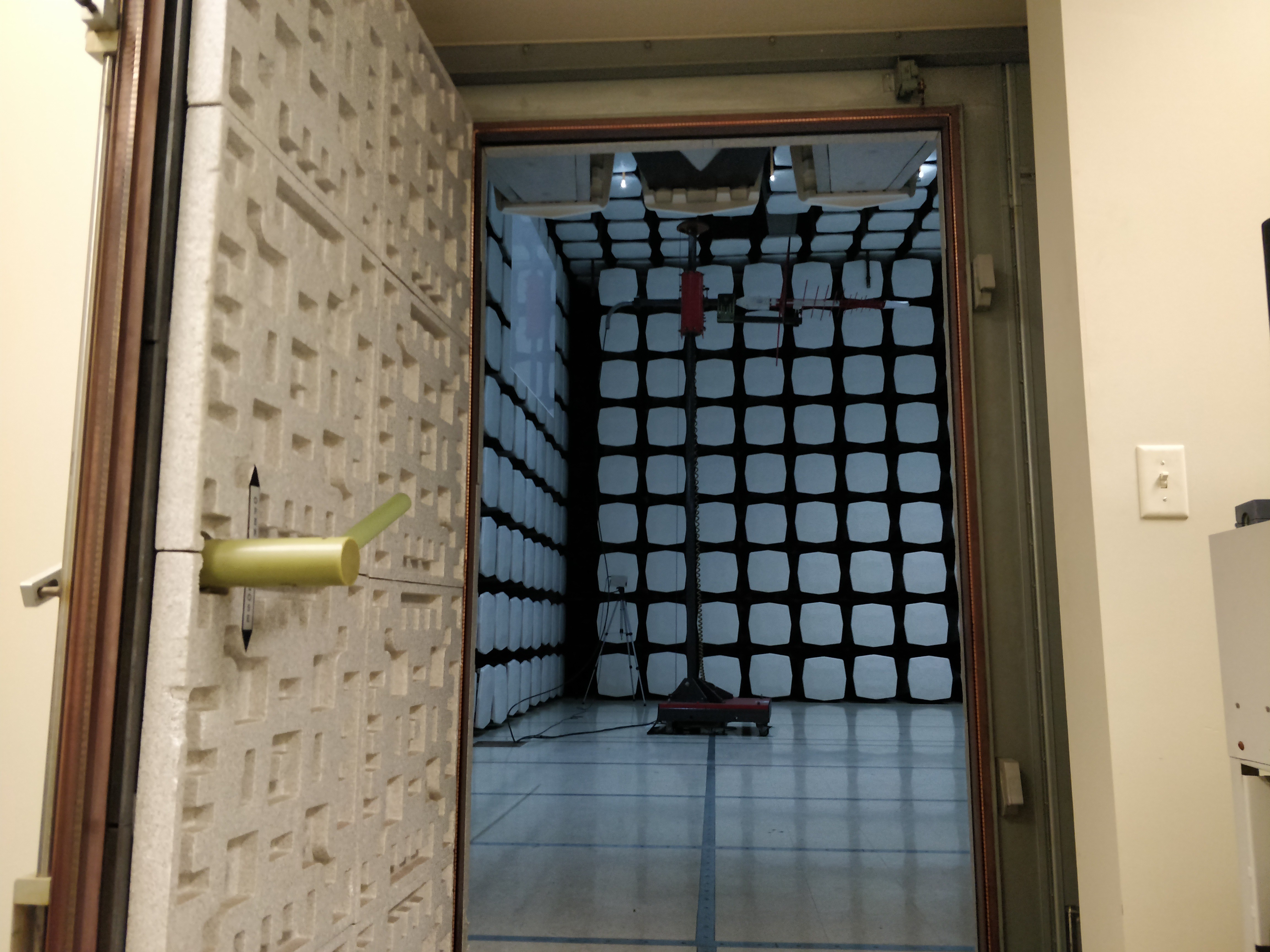
 Above, a full NeuroBytes network test with the NID attached and the tablet graphing real-time data. This graph shows raw cumulative test data and we didn't actually fail in all the spots shown; after running through the quasi-peak detector we found that the first big hump (~30 MHz - 40 MHz) is the one we need to worry about.
 Above, maybe we're on the right track going after the USB cable? The 32 MHz peak is down quite a bit, but the 39 MHz peak jumped a few dBuV/m...
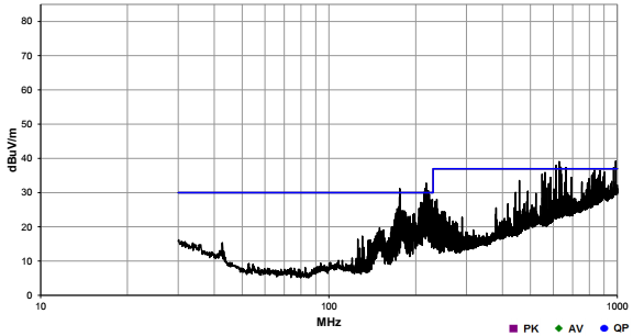 Above, bingo! The two peaks around ~110 MHz wouldn't cause a failure after quasi-peak detection so we're in the clear for a NB-only network.
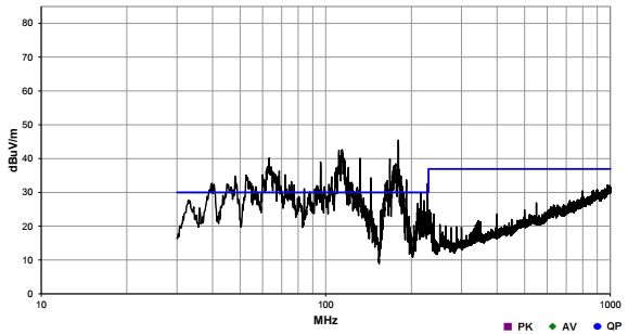 We didn't have time to do anything else, but I'm inclined to think that we were picking up excess EMI from the tablet itself; during testing it sat under the floor but the shielding had a fairly substantial (~150mm) hole, and the USB cable we brought was only 1m long.

 [above, our NeuroBuggy Kit. Designed for building Braitenberg Vehicles and playing around with simple neural network-controlled robotics.]
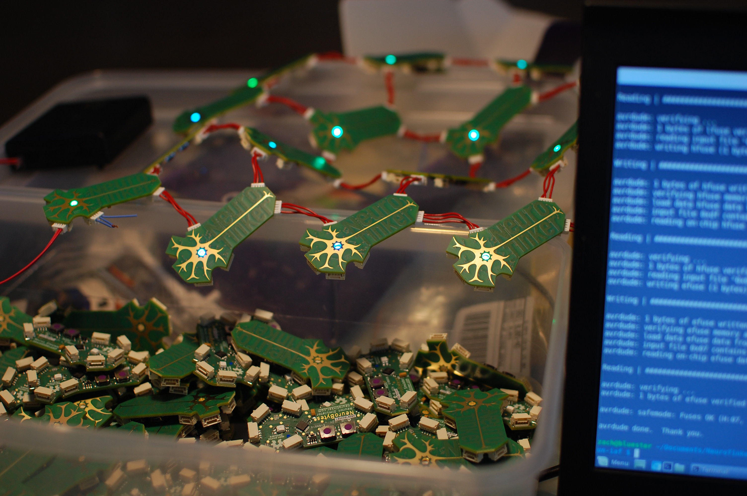
 [img: jumbo-sized and functional NeuroBytes board built for World Maker Faire 2016.]
 In two(ish) months we are launching a crowdfunding campaign (I know... 'ugh'. Agreed. I promise to keep my project log spam to a minimum) with the following nearly finalized boards: