zakqwy
-
Hot Garbage and Iteration
11/14/2016 at 17:20 • 5 commentsHot Garbage, as in poor product design decisions that I am finally fixing. I'm talking, of course, about the first NeuroBytes v0.8 power supply:
![]()
I covered the panicked construction of these power supplies in a previous log. Briefly, I needed a 5VDC power supply that was somewhat self-contained and JST GH compatible, so I bodged the boxes shown above together at the eleventh hour. They were Hot Garbage for any of a number of reasons; in particular, the slide switch was horrifically unreliable and had a nasty habit of pushing into the case after a few uses.
The move to on-board LDOs with NeuroBytes v0.91 meant the power supply boards became a good deal less complex. However, I still made some bad decisions with subsequent iterations:
![]()
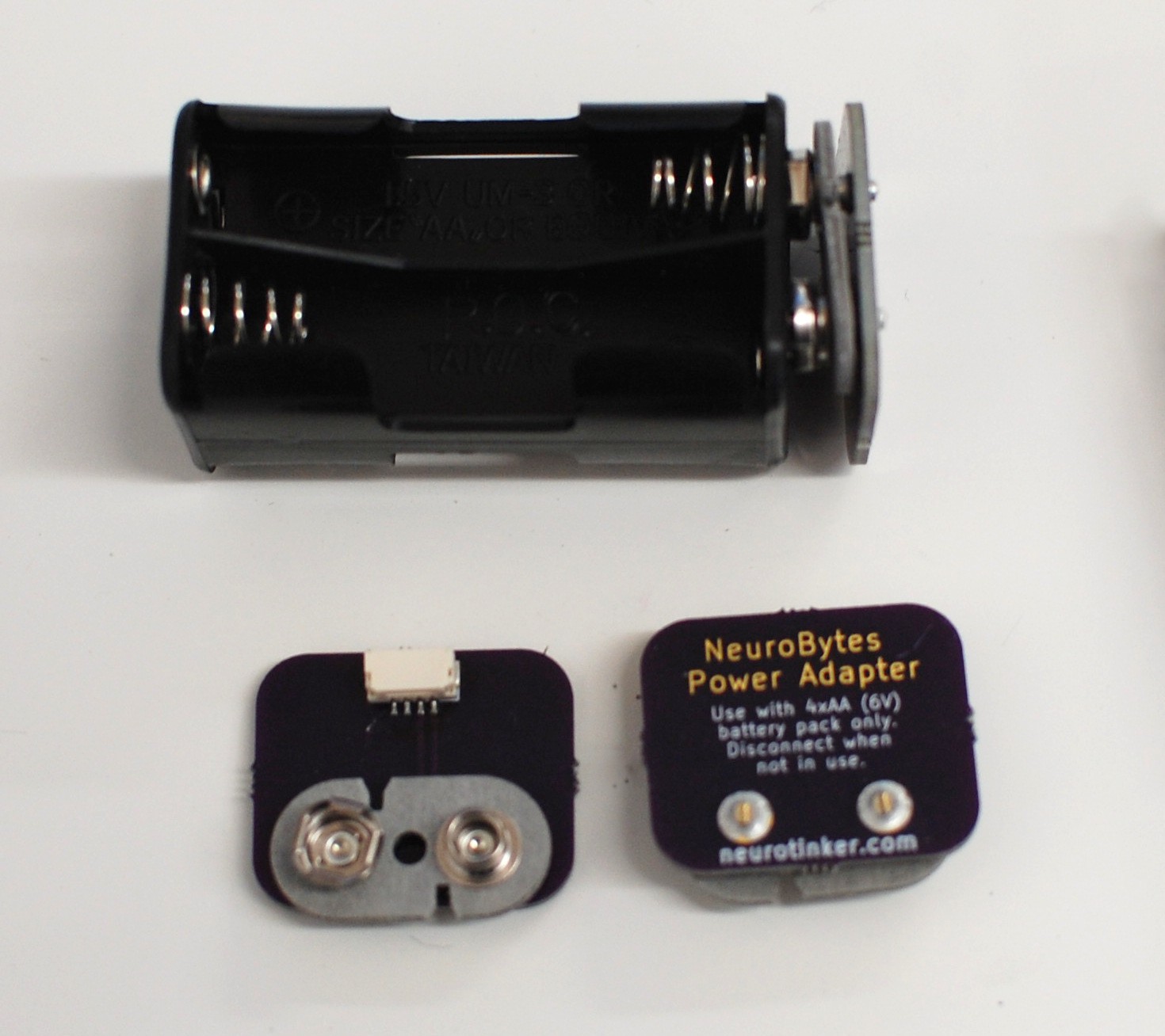
Above: Still not great. The 9vdc snap doesn't sit flat on the 4xAA pack which looks bad. Also, someone could easily hook up a 9vdc battery which wouldn't be great for any number of reasons. No, I won't take a better picture. Sorry.
![]()
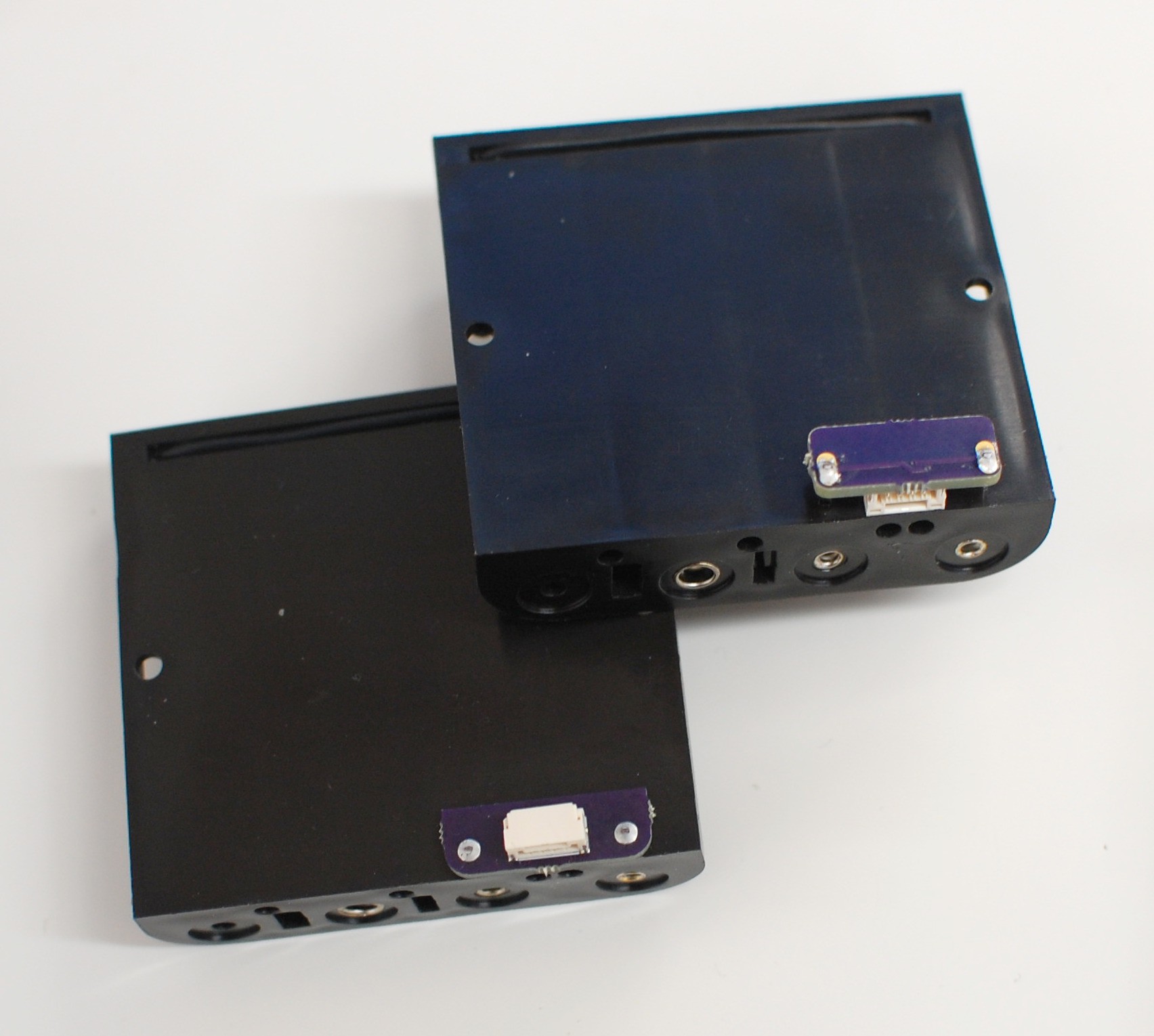
Above: Two similar minimalist options. I tried to make the board as small as possible to minimize cost. Yes, the top right iteration was backwards, so I could either turn the board around or flip it upside-down. Both of these designs were simple enough, but they're also prone to damage when stored loose in a box with heavy batteries installed. Also, the asymmetry means they don't sit flat on the table. A quick fix but in need of another revision.
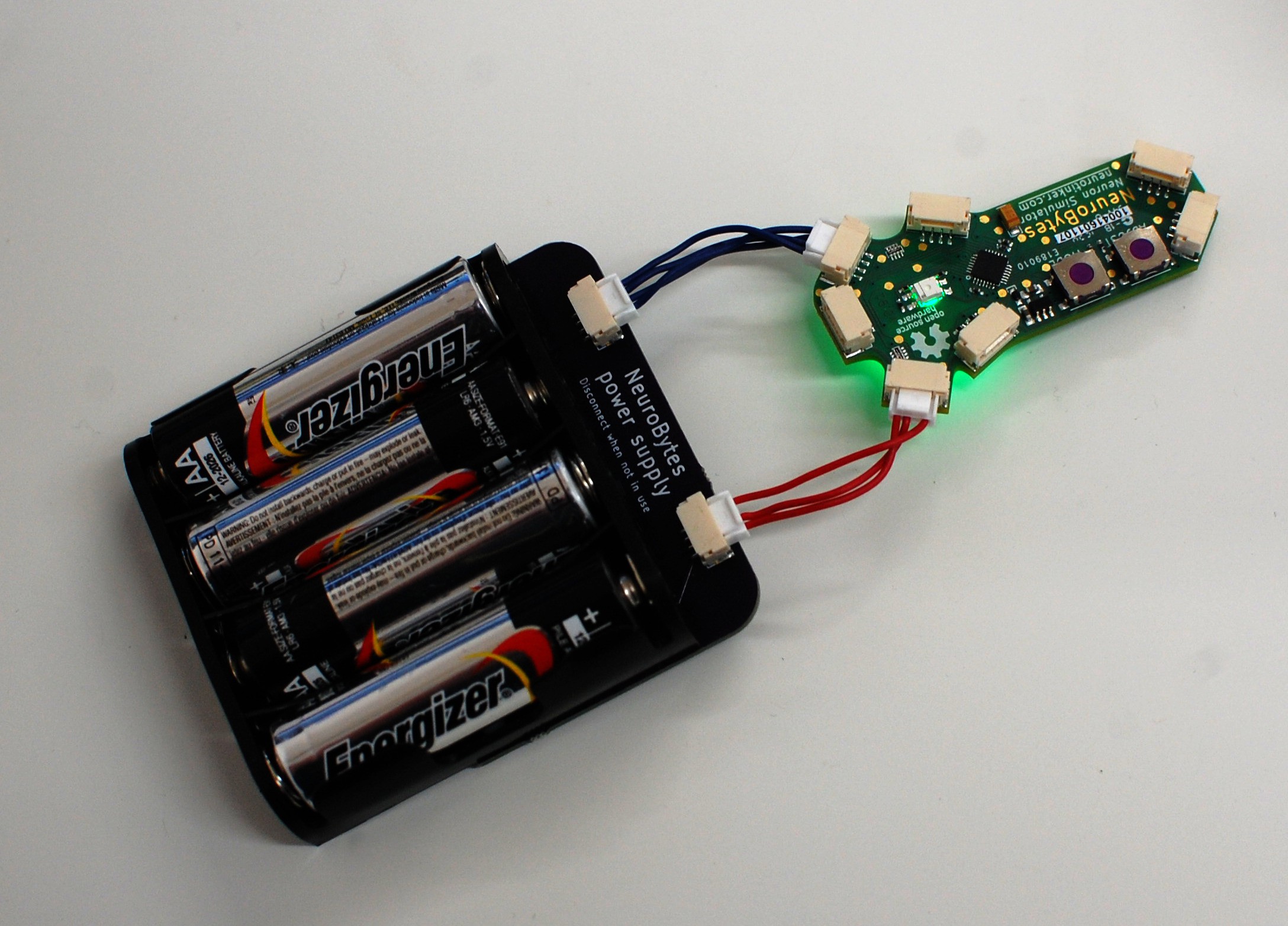
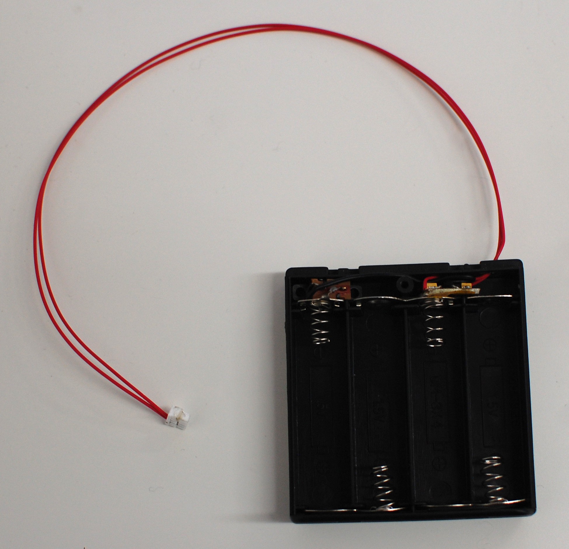
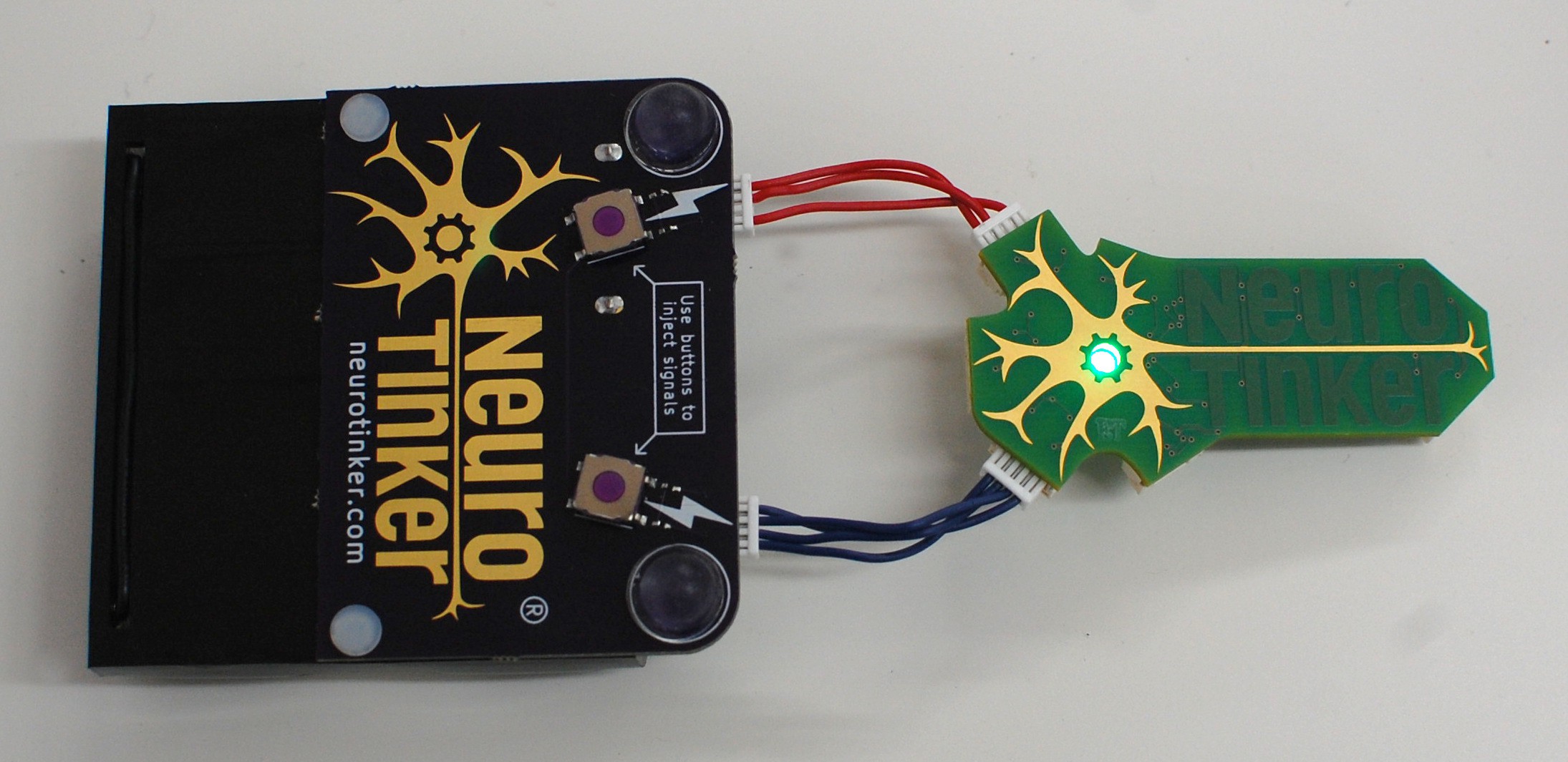
![]() Above and below: Many important changes. For starters, I located a nylon rivet on McMaster that _precisely_ fits the two holes in the battery pack, and is sized right for 1/16" FR4. The rivets are incredibly secure and allowed me to expand the circuit board quite a bit. Secondly, I inset the JST GH connectors a bit; when cables aren't plugged in, they're somewhat protected by the board overhang and are less likely to break off if the battery pack is stored loose in a box. Thirdly, I included test switches for each power jack (along with the now-required resistor divider to avoid sending 6vdc to the ATtiny), greatly improving the usability of the battery pack--now it can fully control a connected central pattern generator circuit. Finally, the pair of stick-on polyurethane bumpers prevent the switches from breaking off. We'll see how well they stay adhered; this power supply is going to get the shoulder bag pocket treatment as a real stress test.
Above and below: Many important changes. For starters, I located a nylon rivet on McMaster that _precisely_ fits the two holes in the battery pack, and is sized right for 1/16" FR4. The rivets are incredibly secure and allowed me to expand the circuit board quite a bit. Secondly, I inset the JST GH connectors a bit; when cables aren't plugged in, they're somewhat protected by the board overhang and are less likely to break off if the battery pack is stored loose in a box. Thirdly, I included test switches for each power jack (along with the now-required resistor divider to avoid sending 6vdc to the ATtiny), greatly improving the usability of the battery pack--now it can fully control a connected central pattern generator circuit. Finally, the pair of stick-on polyurethane bumpers prevent the switches from breaking off. We'll see how well they stay adhered; this power supply is going to get the shoulder bag pocket treatment as a real stress test.![]()
Next steps? Probably one more iteration; I may extend the circuit board a bit to allow more silkscreen documentation (beyond our logo which I like showing off at every possible opportunity). I need to fix a few minor dimensional issues as well, including hole sizes and general alignment. And I'm not convinced the overhang design is the right move; I may keep the board flush with the battery pack and put the connectors on the bottom, along with another pair of bumpers.
-
Documentation Update
10/10/2016 at 23:09 • 0 commentsTime to update the Details page; while the project logs are current, the main NeuroBytes project page is woefully outdated. The pre-10/10/2016 page is shown in this log.
Thanks for checking out NeuroBytes.
![]()
We are excited and honored to be selected as one of the ten Best Product finalists. This section was updated a few times prior to the finals deadline, most recently on 9/21/2015. The previous Details section is here. We also put together a log update that covers the entry requirements.
What are NeuroBytes?
![]()
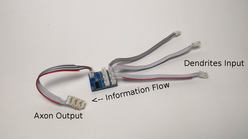
NeuroBytes are tabletop electronic neuron simulators that can be freely connected to form simple biological neural networks. Each element of such a network has a number of inputs, called dendrites, that can be activated by upstream NeuroBytes modules or environmental sensors. The elements, roughly the size of postage stamps, can also send signals to downstream NeuroBytes via an onboard axon connector, or they can activate output devices such as servo motors.
![]() Each NeuroBytes board is powered by an Atmel ATtiny44A microcontroller running various flavors of open-source firmware written in AVR-C. Standard devices are flashed with asimple neuron program that lags severely in one of its timing loops but still manages to dim the on-board RGB LED and keep track of internal membrane potential. Other versions of the code are designed to interface with external devices like hobby servos (both standard and continuous-rotation), touch/light sensors, and MIDI synthesizers (someday!). All of the firmware--and hardware, for that matter--is open source, covered under GPLv3.
Each NeuroBytes board is powered by an Atmel ATtiny44A microcontroller running various flavors of open-source firmware written in AVR-C. Standard devices are flashed with asimple neuron program that lags severely in one of its timing loops but still manages to dim the on-board RGB LED and keep track of internal membrane potential. Other versions of the code are designed to interface with external devices like hobby servos (both standard and continuous-rotation), touch/light sensors, and MIDI synthesizers (someday!). All of the firmware--and hardware, for that matter--is open source, covered under GPLv3.The product is currently in its fourth generation. Previous NeuroBytes iterations, v0.1, v0.2, and v0.3, were progressively refined prototypes that gave our team the confidence to scale up production a bit to produce a usable quantity of devices. The current version was developed with a number of goals in mind chiefly related to low per-unit cost and home manufacturability. The rough BOM cost came to around $3.50/unit (including the circuit board) and once the design was finalized we started producing NeuroBytes.
![]()
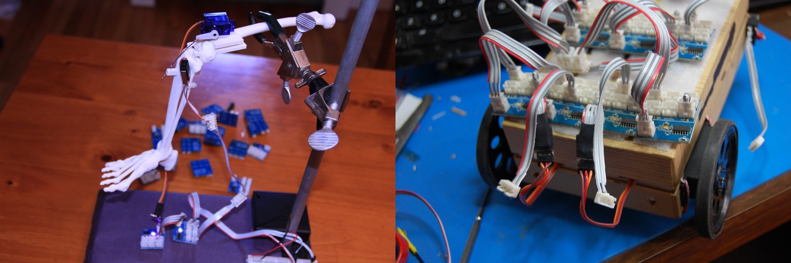
Along with roughly 100+ working devices, we have also put together various accessoriesand sensors, along with a few interesting “case studies”: a skittish cellphone box robot, atwitchy cardboard limb, a touch-sensitive MeArm, and a realistic leg model.
Why are you doing this?
@NeuroJoe said it best in the first part of our THP2k15 finals video: we think neuroscience education is really important. Most major neurological diseases areincurable. We still don't understand basic features of the brain, such as memory and consciousness. So we need to inspire the next generation of scientists to study neuroscience, and that starts with improving STEM education.
We believe that NeuroBytes will increase student engagement with neuroscience, robotics, electrical engineering, and other varied and important fields of study. Our platform is unique in that it is hands-on rather than virtual, and yet still retains the ability to grow with students as they progress through secondary school and higher education.
We also want NeuroBytes to engage the greater programming and hardware communities. Hobbyists and lifelong learners can learn how NeuroBytes are assembled, understand how they are programmed, and ultimately modify how they behave while also gaining new knowledge about anatomy and physiology. To encourage this activity, NeuroBytes are completely open source--both hardware and firmware--licensed under the General Public License, Version 3.
Who are you?
![]()
Joe Burdo is the neuroscientist on the team and works on identifying neuron behavior in real nervous systems to model in a simplified manner, as well as educational curricula. His background is in undergraduate education and neurodegeneration research.
Zach Fredin designed and manufactured the current generation of NeuroBytes prototypes. His background is in materials science and engineering (with a long history of electronics tinkering), so he's been learning a lot about neuroscience as of late.
After collaborating together since February of 2015, we have confirmed that our skills complement each other quite well for this project.
-
Boards look great... [rework LED] ...and they're functional!
09/12/2016 at 23:24 • 0 commentsSeriously, the new boards look amazing; my pictures can't do them justice, so I may actually try flatbed scanning a few when I get home. Needless to say, professionally pasted, placed, reflowed, cleaned, and depanelized boards look a tiny bit better than those I assemble in a toaster oven.
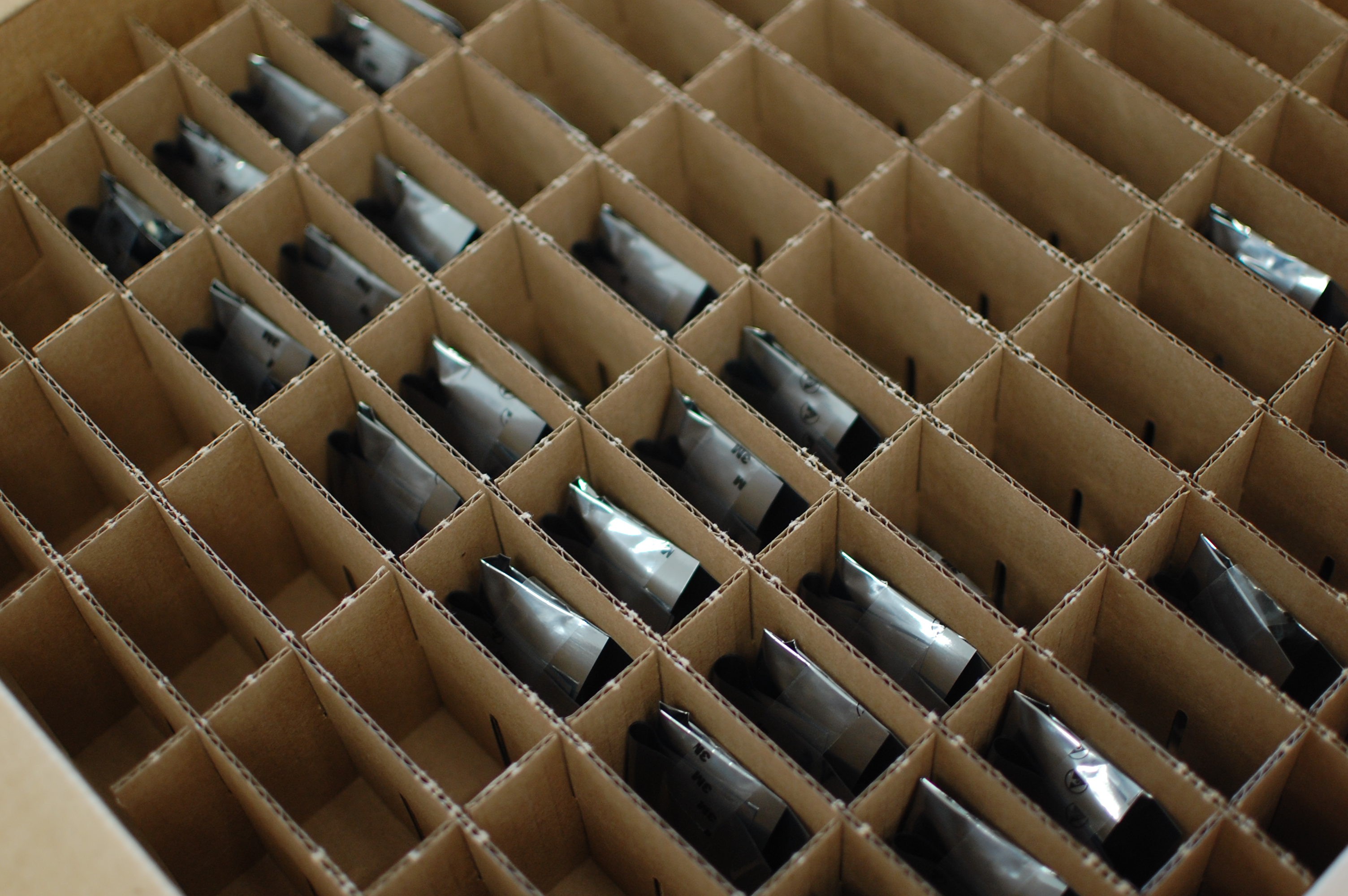
Sadly, the best contract manufacturer around can't escape the power of an incompetent designer [me]. In this case, I (a) misrepresented the rotation angle of the RGB LED on the placement file, and (b) didn't put a clear dot marker on the PCB to indicate orientation. Okay, I didn't put _any_ dot on the PCB, which I will fix shortly. So after driving a few miles (so convenient) and picking the boards up this morning, all wrapped up in their adorable little anti-static bags and safely packaged between some anti-static foam... :
![]()
... I did this:
![]()
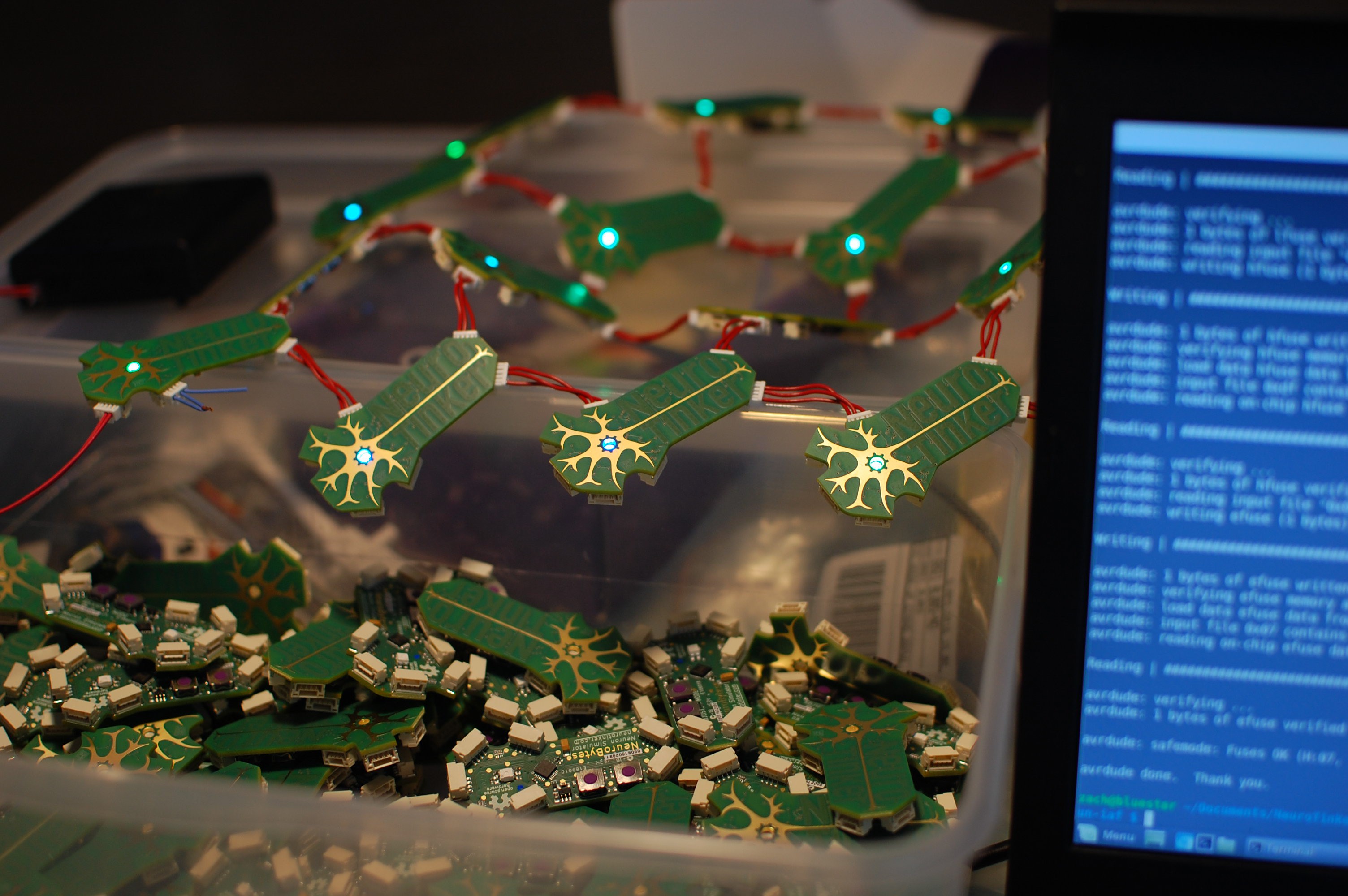
Ouch, painful. Fortunately, I was able to rescue every single LED, clean up each board a tiny bit, and resolder the LEDs in the proper orientation in a few hours. I've only tested 30 or so of the 120-piece run, but every single one works perfectly:
![]()
I also never got around to laser cutting a polycarbonate guide for the v0.91 pogo rig, so programming required a steady hand and careful aim (as the pogo pads are only 1.2mm in diameter):
![]()
However, it all went pretty smoothly now that I finally picked up a fresh cable for my USBtinyISP.
So. Lesson learned? We'll see. Due to an unexpected global shortage of JST GH headers, KeytronicEMS was only able to do a partial run, and that was only because I swung by the plant and dropped off my partial reel left over from v0.8 production (did I mention how much I love having my CM in the same metro area?). It sounds like the balance of the boards will hit the line at the end of the month, and I've already confirmed that they're able to change the machine setup so this problem should be put to bed.
-
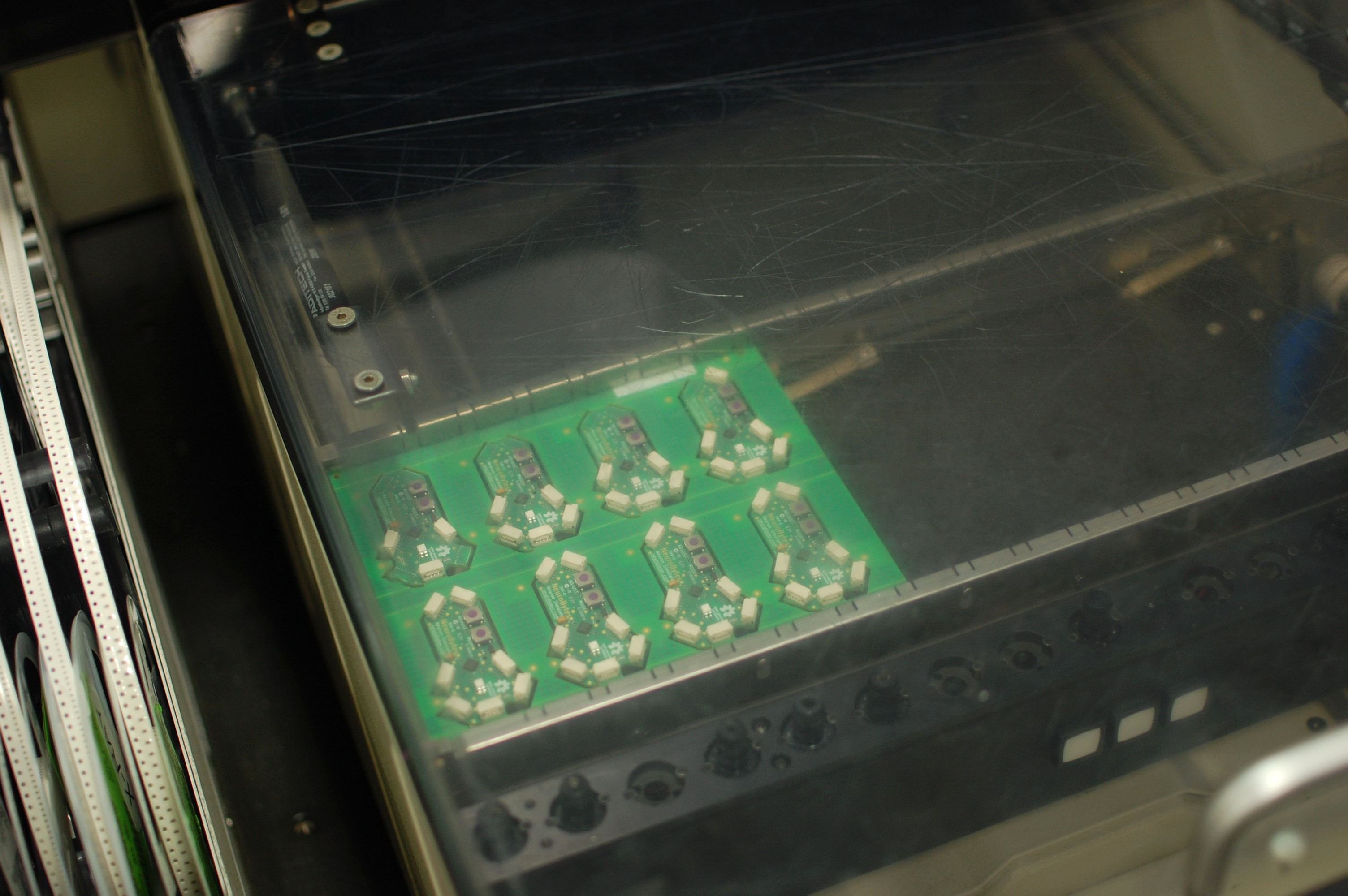
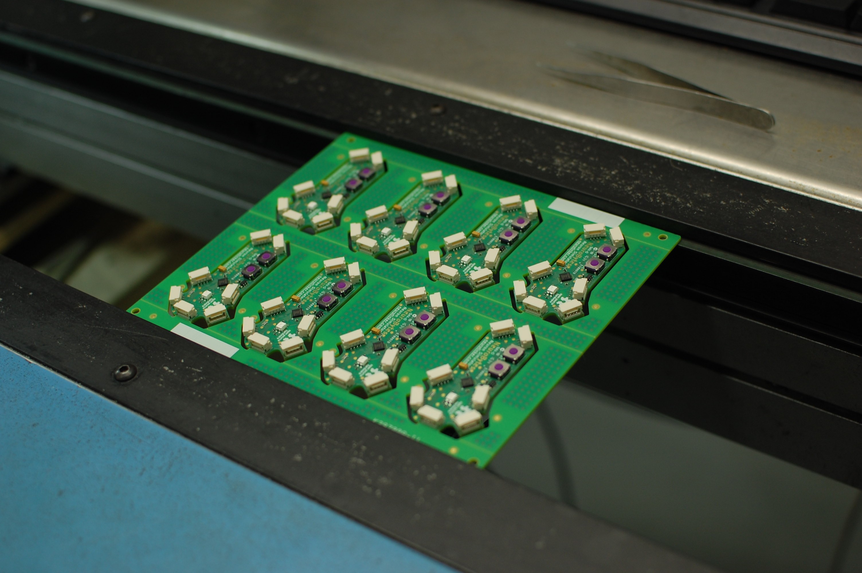
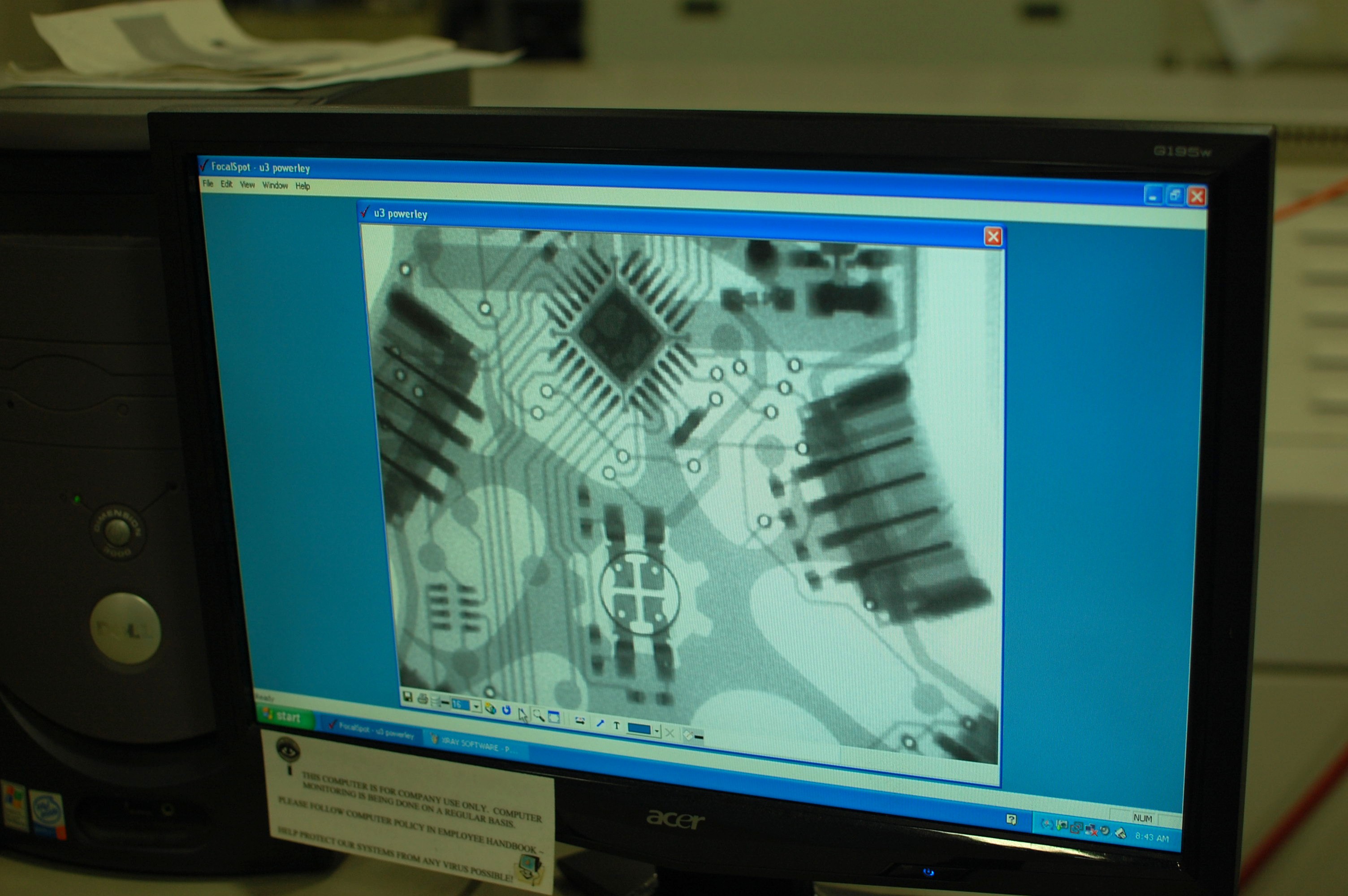
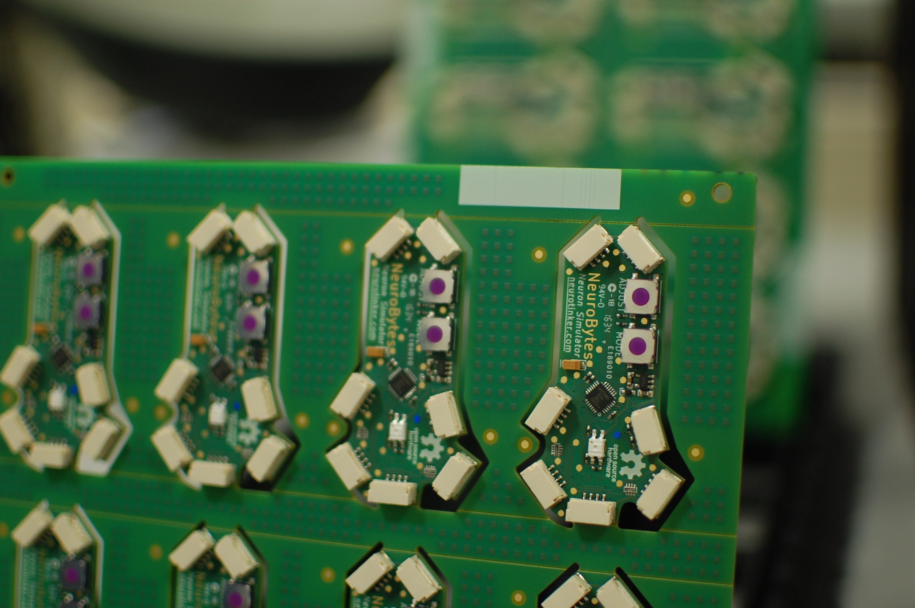
First PnP run!
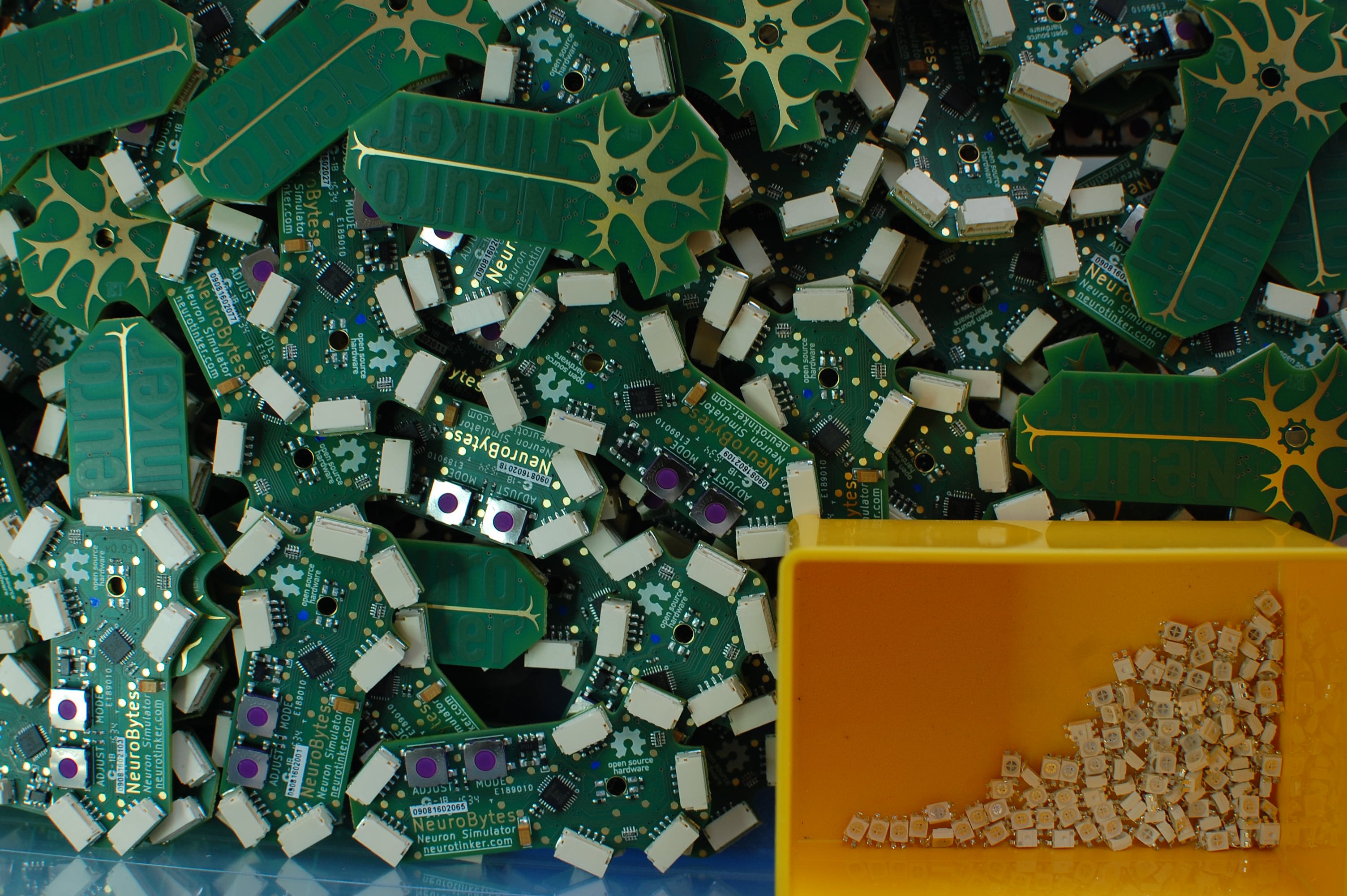
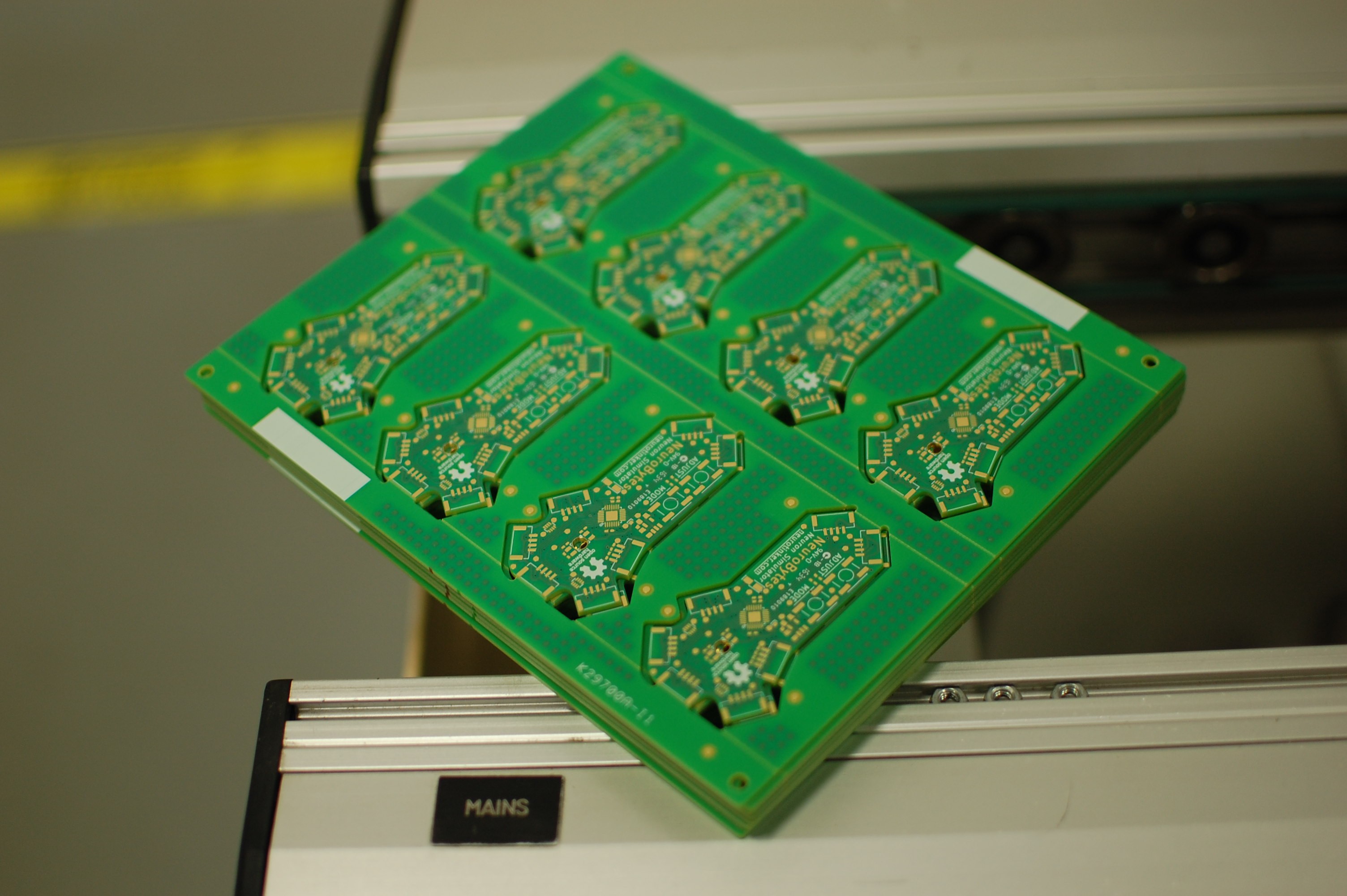
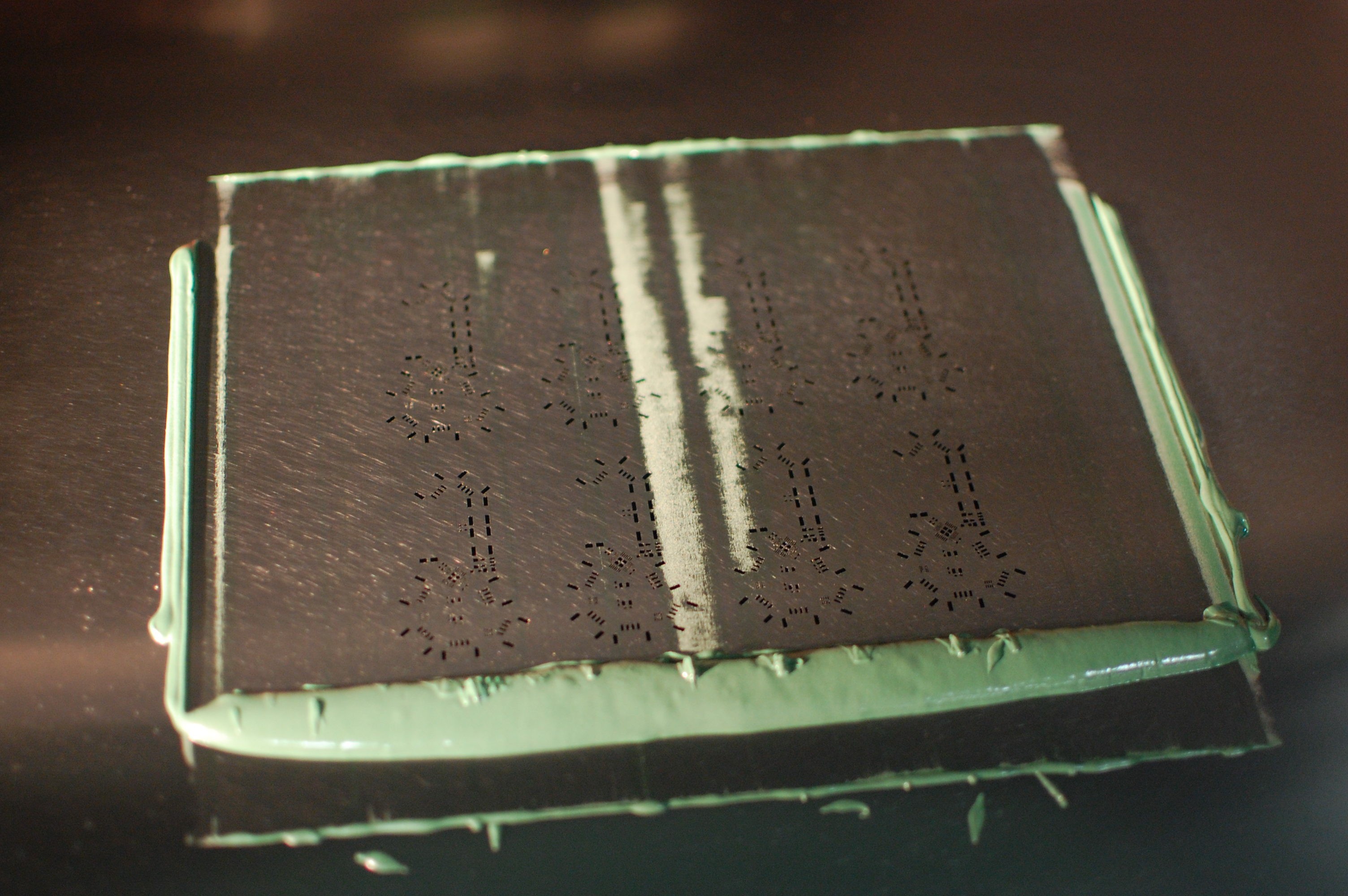
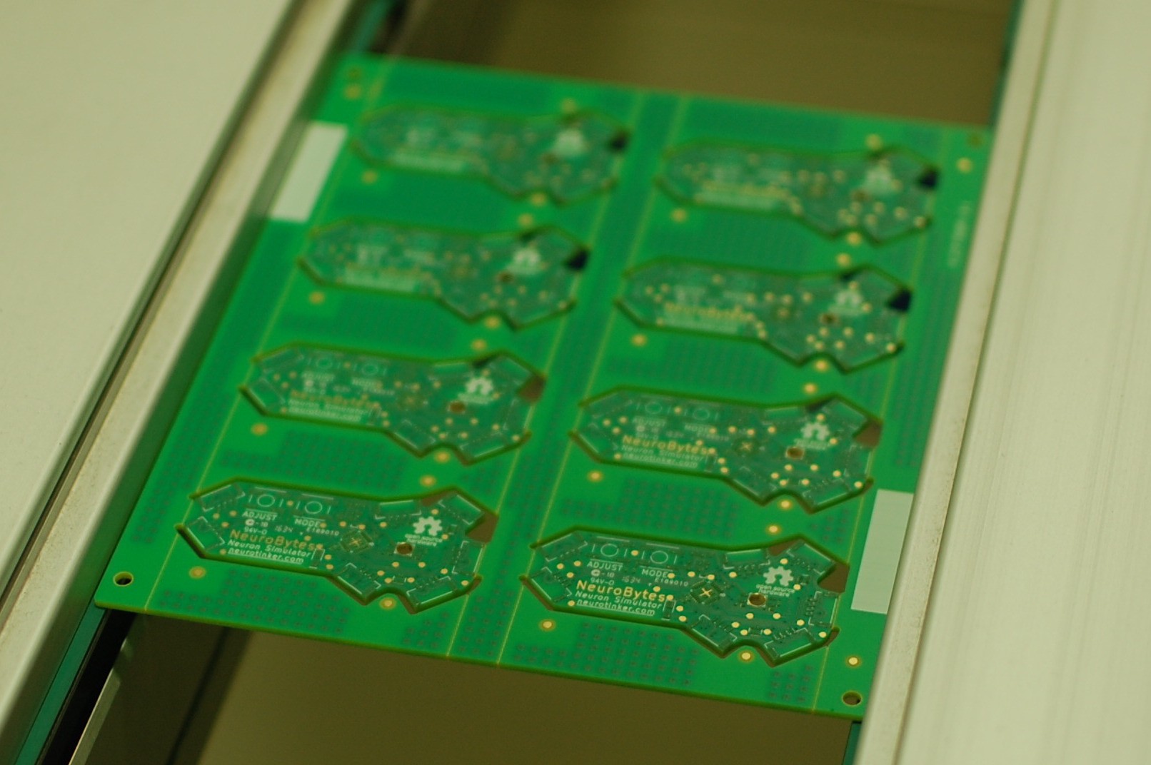
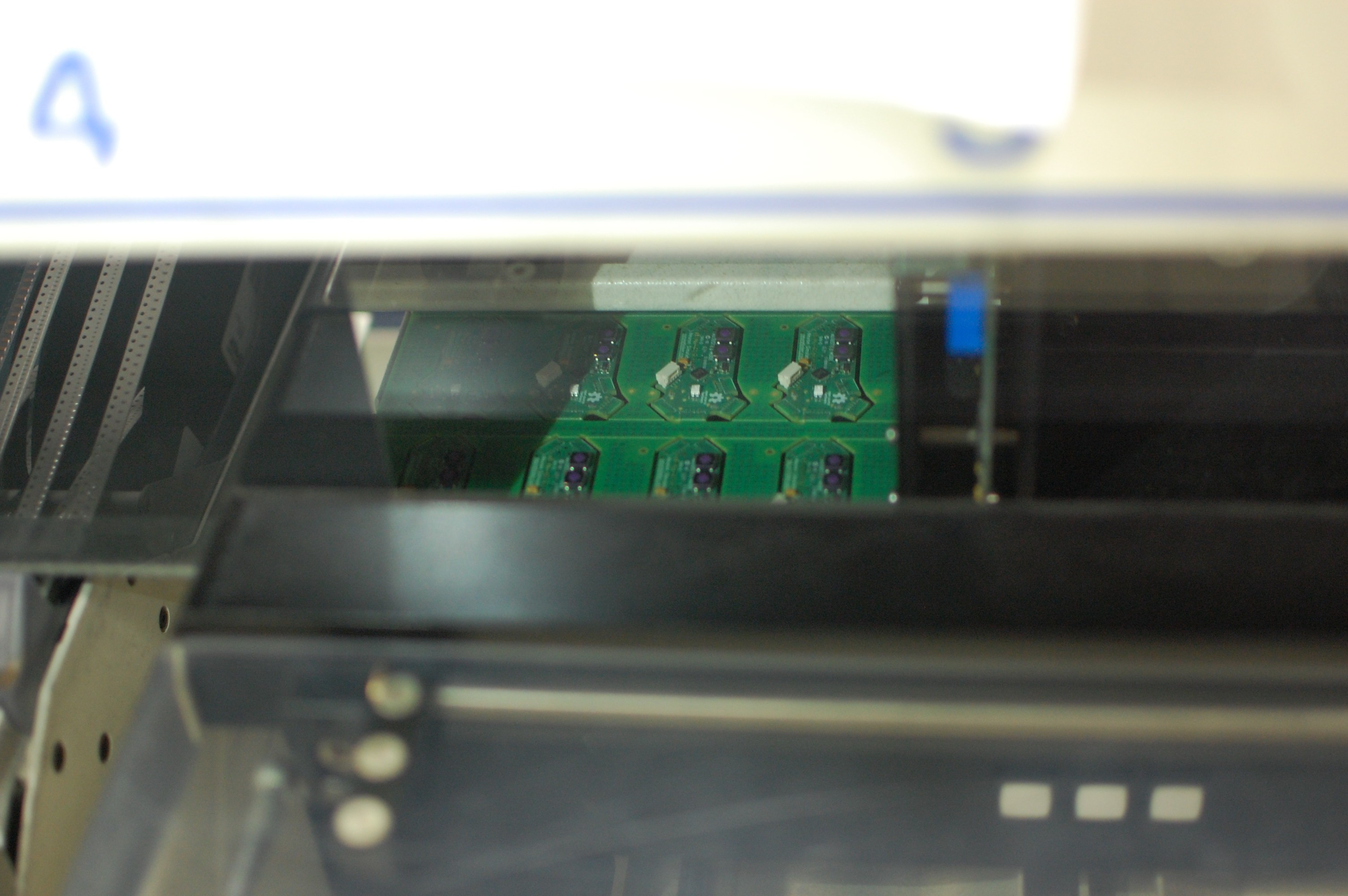
09/08/2016 at 15:31 • 3 commentsMore details to come, along with a the videos I took when I visited my local CM this morning. I'll have the depanelized and washed boards in hand Monday, at which point I'll program and test a few. For now, pictures. And yes, I went with matte green for the v0.91 pilot run!
![]()
![]()
![]()
![]()
![]()
![]()
![]()
![]()
-
NeuroScope, a real-time membrane potential waveform viewer
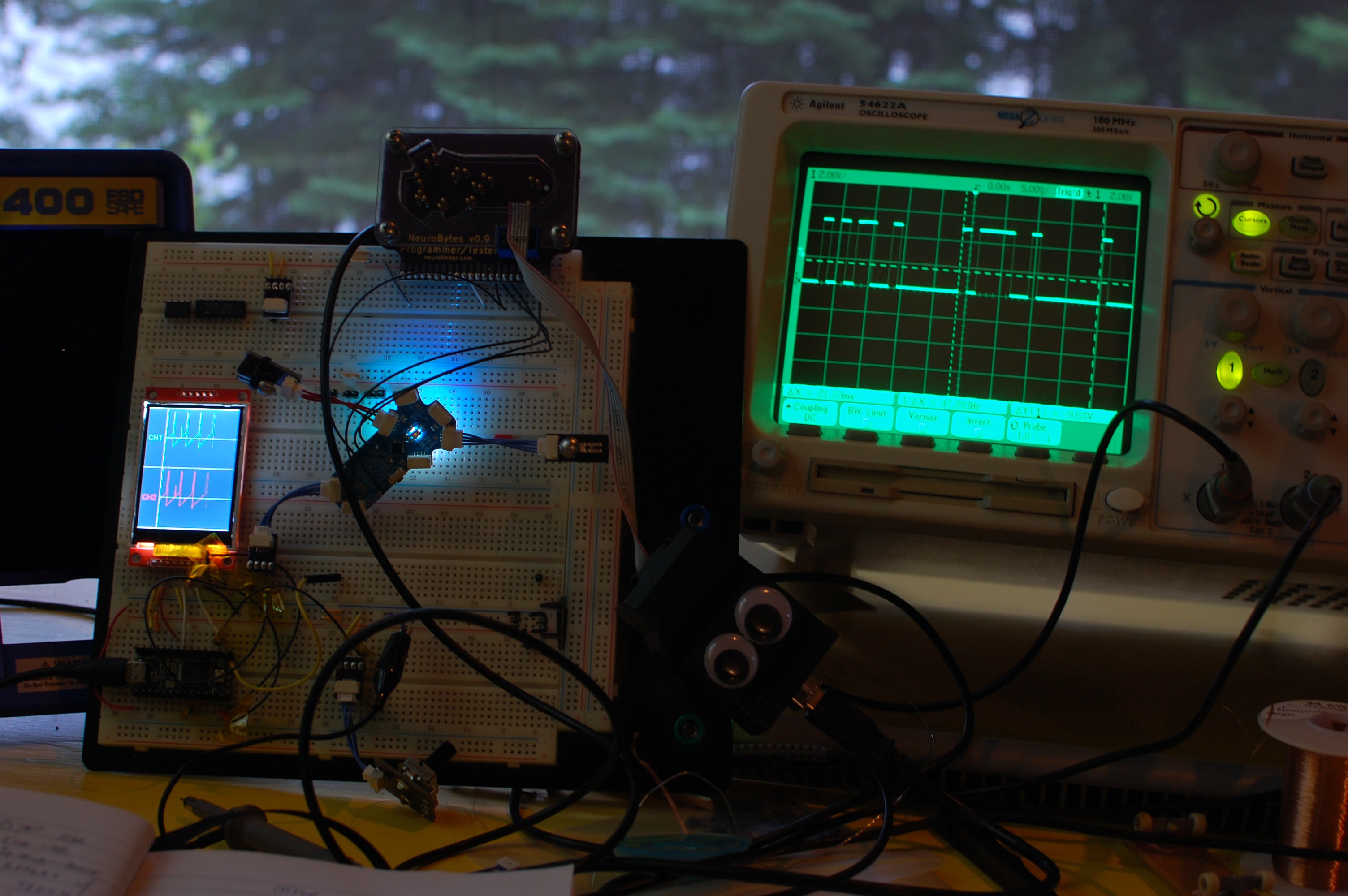
07/15/2016 at 15:04 • 0 commentsThis past weekend I built the first prototype of a new NeuroBytes accessory:
![]()
![]()
Shaky video:
The NeuroScope project has two main components:
- Modifications to the NeuroBytes v0.8 IAF code to (a) lock the main program loop to a stable timebase; (b) convert the current membrane potential to an unsigned 8-bit integer; and (c) send said 8-bit value via UART through one of the axon connectors.
- #Teensy 3.2 pulling in UART data, graphing it on the QVGA TFT LCD, and handling the three input buttons for chart speed and fire counter reset. This is the unit I have left over from @Paul Stoffregen's fantastic #Microcontroller Audio Workshop & HaD Supercon 2015 workshop. He's done great work getting the display to play nice with the Teensy and the Adafruit GFX library, so consider checking it out if you want to quickly add a high-res display to a project.
This is still very much a prototype and the NeuroBytes code isn't integrated into the standard runtime firmware; I still need to figure out how the user will ultimately get data out of the boards, as tying up one of the two axon connectors may not be ideal. A few goals for the next version:
- Improve the serial output function in the NeuroBytes firmware. Adding the timing lock meant dramatically reducing the LED update rate from ~160 Hz to ~70 Hz, as I'm still getting a few pesky delays in the firing routine. I'm working on these issues separately; the plan is to run the LED update as a timer interrupt, but it's still a work in progress. I might also try to expand the bit width of the membrane potential output so I don't need to downconvert the value in firmware.
- Improve the data acquisition code. The serial conversion is a bit glitchy (as shown in the image above), which I believe is traceable to a problem on the Teensy side. Not a huge deal as the program does work, but I think it should be smoother. Also the rate control for the chart doesn't work (although the buttons do change the displayed value).
- Add several channels. The Teensy has three serial ports but for some reason I was only able to get one to work at my funky baud rate. I may have nuked the hardware by accident, but I'm also thinking about other data processing options; since I'm using the internal RC oscillators on the NeuroBytes boards they tend to vary by a decent amount, meaning the NeuroScope needs to handle multiple streams of UART data at slightly different baud rates. I haven't stuck a toe into the FPGA world but I think this could be a great application for an iCE40 or a similar low-price device. If I can offload input signal consolidation to that platform and then send the raw data into the Teensy via higher speed SPI (or something), I should be able to support tons of channels without too much trouble (ha!).
- Datalogging. I'd like to log the data directly to an SD card in *.csv format for offline analysis. I think this mght be useful for running longer term experiments and it shouldn't be a huge processor burden.
- Rate measurement. Right now I count action potentials by looking for the MP to exceed a threshold. It should be fairly simple to convert this to a moving-average rate display, which will also greatly help with more advanced experimentation.
Here are the code modifications for the NeuroBytes boards (only the changes are shown for simplicity), along with the complete Teensy program. As mentioned above, this is a prototype so I don't suggest using this code yourself, but if you want to it's all covered under GPL v3.0 (as with the rest of the project). The code snippits are the last item in this post, so feel free to stop reading here if you like.
NeuroBytes code
convert membrane potential value:
			else if (t_var_timer == 20) {
			//	added scope scaling deal-o
			//	o_var_8bit = (uint8_t)((n_var_v + o_con_offset) << 8);
			//	o_var_8bit = (uint8_t)((n_var_v) << 8);
				if (t_var_fire < t_var_fire_reset) {
					o_var_8bit = 200;
				}
				else {
					o_var_8bit = (uint8_t)((n_var_v + 250 - 32767) >> 2);
				}
... UART out on axon:else if (t_var_timer == 21) { if (o_var_serial_count == 0) { PORTB |= (1<<PB2); } if (o_var_serial_count == 1) { PORTB &= ~(1<<PB2); } else if ((o_var_serial_count > 1) && (o_var_serial_count <= 9)) { if ((o_var_8bit & (1<<(o_var_serial_count - 2))) > 0) { PORTB |= (1<<PB2); } else { PORTB &= ~(1<<PB2); } } else if (o_var_serial_count > 9) { PORTB &= ~(1<<PB2); } if (o_var_serial_count == 15) { o_var_serial_count = 0; } else { o_var_serial_count++; }... ISR and timer setup:
ISR(TIMER0_COMPA_vect) {
	t_var_tick = 1;
}

/* set up Timer/Counter0 for main loop timing */
	TCCR0A |= (1<<CTC0); //clear timer compare mode
	TCCR0A |= (1<<CS01); //prescale to clk/8 (1 MHz)
	OCR0A = 60;
	TIMSK0 |= (1<<OCIE0A); //enable Compare Match A interrupt

int main(void) {
	systemInit();
	uint8_t i;
/*
	for (i=0;i<60;i++) {
		n_var_v_delay[i] = 32767;
	}
*/
	for(;;) {
		while (t_var_tick == 0) {}
		cli();
		t_var_tick = 0;
[... ]
Teensy code:#include <ILI9341_t3.h> #include <SPI.h> #include <font_Arial.h> #include <font_ArialBold.h> #define TFT_DC 21 #define TFT_CS 20 #define TFT_RST 255 #define TFT_MOSI 11 #define TFT_SCLK 14 #define TFT_MISO 12 #define BUTTON0 19 #define BUTTON1 16 #define BUTTON2 18 ILI9341_t3 tft = ILI9341_t3(TFT_CS, TFT_DC, TFT_RST, TFT_MOSI, TFT_SCLK, TFT_MISO); unsigned long baud_rate; unsigned long baud_rate_prev = 0; int incomingByte; int incomingBytePrev; int i = 0; int i_prev = 0; int ap_count = 0; int ap_count_prev = -1; int ap_reset = 0; int spm = 16; int spm_prev = 0; int button1_prev = 0; int button2_prev = 0; void drawBorders_2ch() { tft.drawFastHLine(0,0,239,ILI9341_WHITE); tft.drawFastHLine(0,158,239,ILI9341_WHITE); tft.drawFastHLine(0,318,239,ILI9341_WHITE); tft.drawFastHLine(51,79,189,ILI9341_DARKGREY); tft.drawFastHLine(51,237,189,ILI9341_DARKGREY); tft.drawFastVLine(50,0,319,ILI9341_WHITE); } void drawLabels_2ch() { tft.setTextColor(ILI9341_GREEN); tft.setFont(Arial_14); tft.setCursor(5,73); tft.print("CH1"); tft.setTextColor(ILI9341_RED); tft.setCursor(5,231); tft.print("CH2"); } void refreshGraphs_2ch() { tft.fillRect(51,1,190,157,ILI9341_BLACK); tft.fillRect(51,159,190,158,ILI9341_BLACK); tft.drawFastHLine(51,79,189,ILI9341_DARKGREY); tft.drawFastHLine(51,237,189,ILI9341_DARKGREY); } void drawBorders_1ch() { tft.drawFastVLine(226,0,319,ILI9341_WHITE); tft.drawFastVLine(188,176,20,ILI9341_WHITE); tft.drawFastVLine(188,280,20,ILI9341_WHITE); tft.drawFastHLine(188,176,45,ILI9341_WHITE); tft.drawFastHLine(188,300,45,ILI9341_WHITE); tft.drawFastHLine(157,264,63,ILI9341_WHITE); tft.drawFastHLine(0,120,226,ILI9341_DARKGREY); } void drawLabels_1ch() { tft.setTextColor(ILI9341_WHITE); tft.setFont(Arial_9); tft.setRotation(135); tft.setCursor(253,229); tft.print("RESET"); tft.setRotation(0); tft.setCursor(230,171); tft.print("+"); tft.setCursor(231,288); tft.print("_"); tft.setFont(Arial_9); tft.setCursor(166,199); tft.print("CHART"); tft.setCursor(166,211); tft.print("SPEED"); tft.setCursor(157,252); tft.print("SCREENS"); tft.setCursor(165,267); tft.print("MINUTE"); tft.setCursor(5,185); tft.print("MEMBRANE"); tft.setCursor(10,197); tft.print("POTENTIAL"); tft.setCursor(52,228); tft.print("FIRE"); tft.setCursor(36,240); tft.print("COUNT"); tft.setCursor(44,271); tft.print("BAUD"); tft.setCursor(46,283); tft.print("RATE"); } void refreshData_1ch() { tft.setFont(Arial_16_Bold); tft.setTextColor(ILI9341_WHITE); if (spm != spm_prev) { tft.fillRect(175,228,40,16,ILI9341_BLACK); tft.setCursor(175,228); tft.print(spm); spm_prev = spm; } if (incomingBytePrev != incomingByte) { tft.fillRect(90,189,60,16,ILI9341_BLACK); tft.setCursor(90,189); tft.print(incomingByte); } if (ap_count != ap_count_prev) { tft.fillRect(90,231,40,16,ILI9341_BLACK); tft.setCursor(90,231); tft.print(ap_count); ap_count_prev = ap_count; } if (baud_rate != baud_rate_prev) { tft.fillRect(90,273,60,16,ILI9341_BLACK); tft.setCursor(90,273); tft.print(baud_rate); baud_rate_prev = baud_rate; } tft.setFont(Arial_9); } void refreshGraphs_1ch() { tft.fillRect(0,0,226,157,ILI9341_BLACK); tft.drawFastHLine(0,120,226,ILI9341_DARKGREY); } void updateButtonGraphic(int buttonID, int state) { /* * buttonID: 0 = top, 1 = middle, 2 = bottom * state: 0 = released, 1 = pressed */ switch (buttonID) { case 0: tft.setRotation(135); if (state == 0) { tft.setTextColor(ILI9341_WHITE); tft.fillRect(250,227,50,13,ILI9341_BLACK); } else { tft.setTextColor(ILI9341_BLACK); tft.fillRect(250,227,50,13,ILI9341_WHITE); } tft.setFont(Arial_9); tft.setCursor(253,229); tft.print("RESET"); tft.setRotation(0); break; case 1: if (state == 0) { tft.setTextColor(ILI9341_WHITE); tft.fillRect(227,151,13,50,ILI9341_BLACK); } else { tft.setTextColor(ILI9341_BLACK); tft.fillRect(227,151,13,50,ILI9341_WHITE); } tft.setFont(Arial_9); tft.setCursor(230,171); tft.print("+"); break; case 2: if (state == 0) { tft.setTextColor(ILI9341_WHITE); tft.fillRect(227,275,13,50,ILI9341_BLACK); } else { tft.setTextColor(ILI9341_BLACK); tft.fillRect(227,275,13,50,ILI9341_WHITE); } tft.setFont(Arial_9); tft.setCursor(231,288); tft.print("_"); break; } } void addPoint(int ch, int t, int val_raw) { int x = t + 51; int y; if (ch == 1) { y = 79 + 62 - val_raw; tft.drawPixel(x,y,ILI9341_GREEN); } else if (ch == 2) { y = 237 + 62 - val_raw; tft.drawPixel(x,y,ILI9341_RED); } } void addConnectedPoint(int ch, int t, int t_prev, int val_raw, int val_raw_prev) { int x = t; int x_prev = t_prev; int y; int y_prev; if (x_prev < x) { if (ch == 1) { y = 120 + 31 - (val_raw >> 1); y_prev = 120 + 31 - (val_raw_prev >> 1); tft.drawLine(x_prev,y_prev,x,y,ILI9341_GREEN); } } } void setup() { delay(500); tft.begin(); tft.fillScreen(ILI9341_BLACK); drawBorders_1ch(); drawLabels_1ch(); pinMode(BUTTON0, INPUT); pinMode(BUTTON1, INPUT); pinMode(BUTTON2, INPUT); pinMode(1, INPUT); baud_rate = 765; Serial3.begin(baud_rate); } void loop() { //baud_rate = map(analogRead(1),150,870,650,800); //Serial3.begin(baud_rate); if (Serial3.available()) { incomingBytePrev = incomingByte; incomingByte = Serial3.read(); } if ((incomingByte > 110) && (ap_reset == 0)) { ap_count++; ap_reset = 1; tft.drawFastVLine(i,10,20,ILI9341_RED); } if ((incomingByte < 50) && (ap_reset == 1)) { ap_reset = 0; } if ((digitalRead(BUTTON1) && (button1_prev == 0)) && (spm < 64)) { spm<<=1; } if ((digitalRead(BUTTON2) && (button2_prev == 0)) && (spm > 1)) { spm>>=1; } button1_prev = digitalRead(BUTTON1); button2_prev = digitalRead(BUTTON2); if (digitalRead(BUTTON0)) { ap_count_prev = ap_count; ap_count = 0; } updateButtonGraphic(0,digitalRead(BUTTON0)); updateButtonGraphic(1,digitalRead(BUTTON1)); updateButtonGraphic(2,digitalRead(BUTTON2)); refreshData_1ch(); addConnectedPoint(1,i,i_prev,incomingByte,incomingBytePrev); i_prev = i; i++; if (i == 226) { i = 0; refreshGraphs_1ch(); } if (i == 0) { i_prev = 226; } delay(10); } -
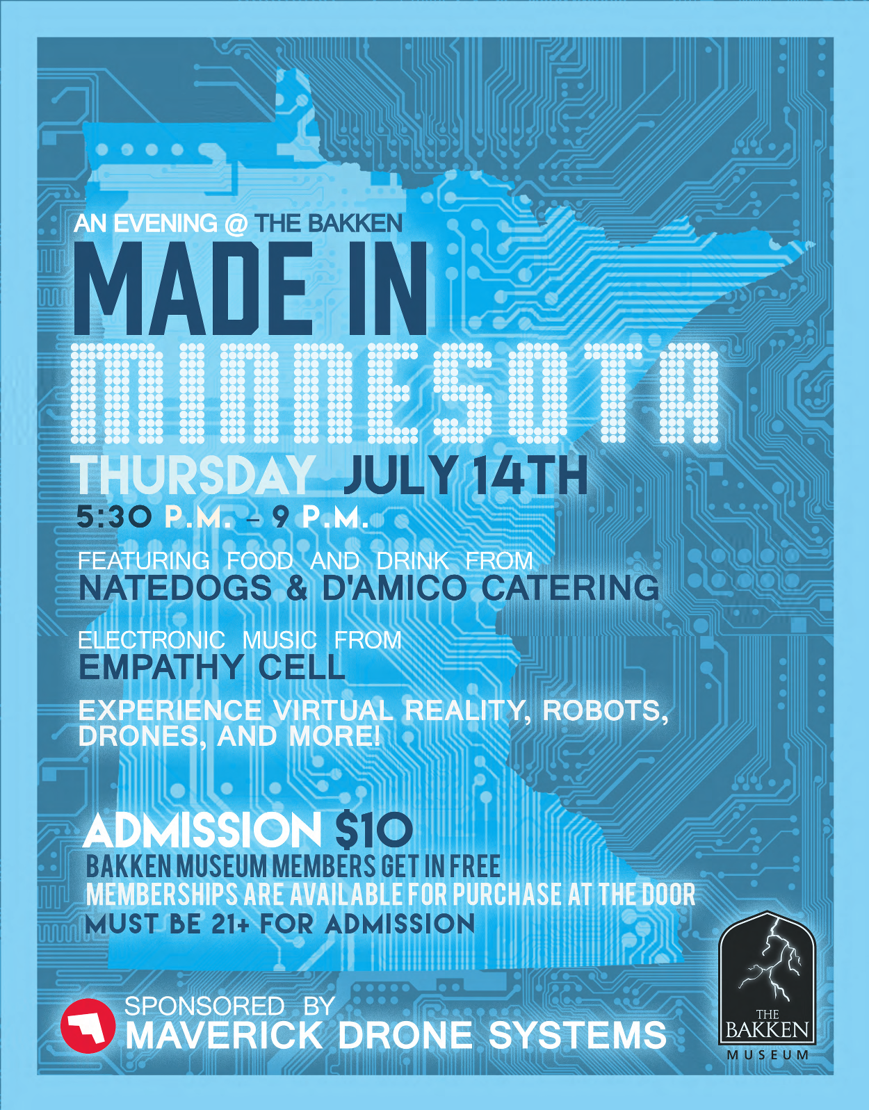
Live in MN? Don't miss NeuroBytes at the Bakken's 21+ event next month!
06/23/2016 at 19:50 • 0 comments![]()
We'll have a table showing off our NeuroBytes along with three simulations:
- Patellar reflex
- Eye
- Crawler
Should be an excellent time. Don't miss it if you live within driving distance of Mpls!
-
NeuroTinker (R), still (and forever) OSHW
06/18/2016 at 14:33 • 0 commentsWe just received notification from the USPTO that our trademark submission has been accepted and published in the latest Trademark Official Gazette!
So yeah. That means the NeuroTinker logo is a registered trademark, so we get to use the little circle R icon:
Getting our logo trademarked protects the NeuroTinker brand. It's an important step towards building our business, and it's the same path followed by other open-source educational hardware companies including Arduino, littleBits, and others. Importantly, it means that other organizations can't sell products that include the NeuroTinker logo without our explicit permission.![]()
Okay all of that is boring. I'm putting up this post to talk about what the trademark doesn't mean--in particular, it doesn't affect our commitment to OSH.
NeuroTinker is committed to open-source hardware. We literally wouldn't exist without OSHW (and Hackaday.io, for that matter). Our products, including NeuroBytes (incidentally, our only product at this point in time), will always be released under a share-alike open-source license that complies with the guidelines established by the Open Source Hardware Association. That means making every effort to thoroughly document the project, supporting community-driven development endeavors, releasing broadly compatible design files in a timely manner, and so forth (read the whole document, it's filled with a lot of good stuff).
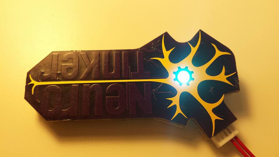
Things get a bit complicated because our latest NeuroBytes hardware iterations use our logo as part of the circuit; in particular, the neuron symbol acts as a ground plane and the gear at the center of the cell highlights the indicator LED. Generally, that means anyone interested in building NeuroBytes based explicitly off our board design would need to modify this portion of the layout prior to selling them commercially. I don't believe this will be an issue, but if you feel otherwise please let me know in the comments.
-
littleBits-->NeuroBytes adapter
06/04/2016 at 21:05 • 0 commentsA @littleBits to NeuroBytes input adapter has been on the back burner for far too long. Today, I used my Hardware Development Kit Proto Module to tie directly into a NeuroBytes v0.8 board:
During the v0.8 design, I didn't intend to use any of the ATtiny88's analog input channels. However, by a happy coincidence a few of them corresponded with the six ADC channels; in particular, I was able to use the Dendrite 4 signal pin as it ran to PC5, which is ADC5. This pin is connected directly to the littleBits signal line in the video above, which varies between 0 and 5 VDC during operation. I modified the v0.8 Izhikevich code to pull membrane current from this ADC channel after a double right shift; this scales the ADC channel from 0 to 63:
//ADC setup:

DDCR &= ~(1<<PC5); //only need PC5 (ADC5, dend4) set as an input
PRR &= ~(1<<PRADC); //ensures power reduction bit is cleared
ADCSRA |= (1<<ADEN); //enables the ADC
ADCSRB = 0; //ensures ADTS[0:2] = 0 for Free Running Mode
ADCSRA |= ((1<<ADPS2) | (1<<ADPS1)); //prescales ADC clock to clk/64 (125 kHz)
ADMUX |= ((1<<MUX2) | (1<<MUX0)); //MUX[3:0] = 0101 selects ADC5 (before start command!)
ADMUX |= (1<<ADLAR); //left adjusts ADC result
ADMUX |= (1<<REFS0); //ensures ADC references AVCC
//updateModel(uint8_t stage) change to pull in ADC result: if (stage == 0) { ADCSRA |= (1<<ADSC)); //starts running ADC conversion } if (stage == 1) { I = (ADCH >> 2); //sets Izhikevich membrane current value to Dendrite 4 input value (scaled 0..63) }The potentiometer input video is a pretty basic demonstration of the effects of changing the Izhikevich membrane current value between 0 and 63 has on the NeuroBytes board firing rate. Stuff gets a lot cooler once you attach a littleBits Light Sensor Bit, switched to Dark mode with the sensitivity adjusted to detect the shadow from my hand:
The video above is interesting because it's a blinky LED that responds to ambient conditions. It's amazing because this actually demonstrates how photoreceptors in your eye function; as much better explained in the Khan Academy video below, a presence of light causes the rod cell to hyperpolarize and stop firing:
NeuroBytes v0.91 boards were ordered yesterday, and among several other changes to fix previously discussed problems with v0.9, they have all five dendrite signal lines connected to ADC inputs. You can probably see where this is going, but if not--just know that I'm about to order a lot of littleBits.
-
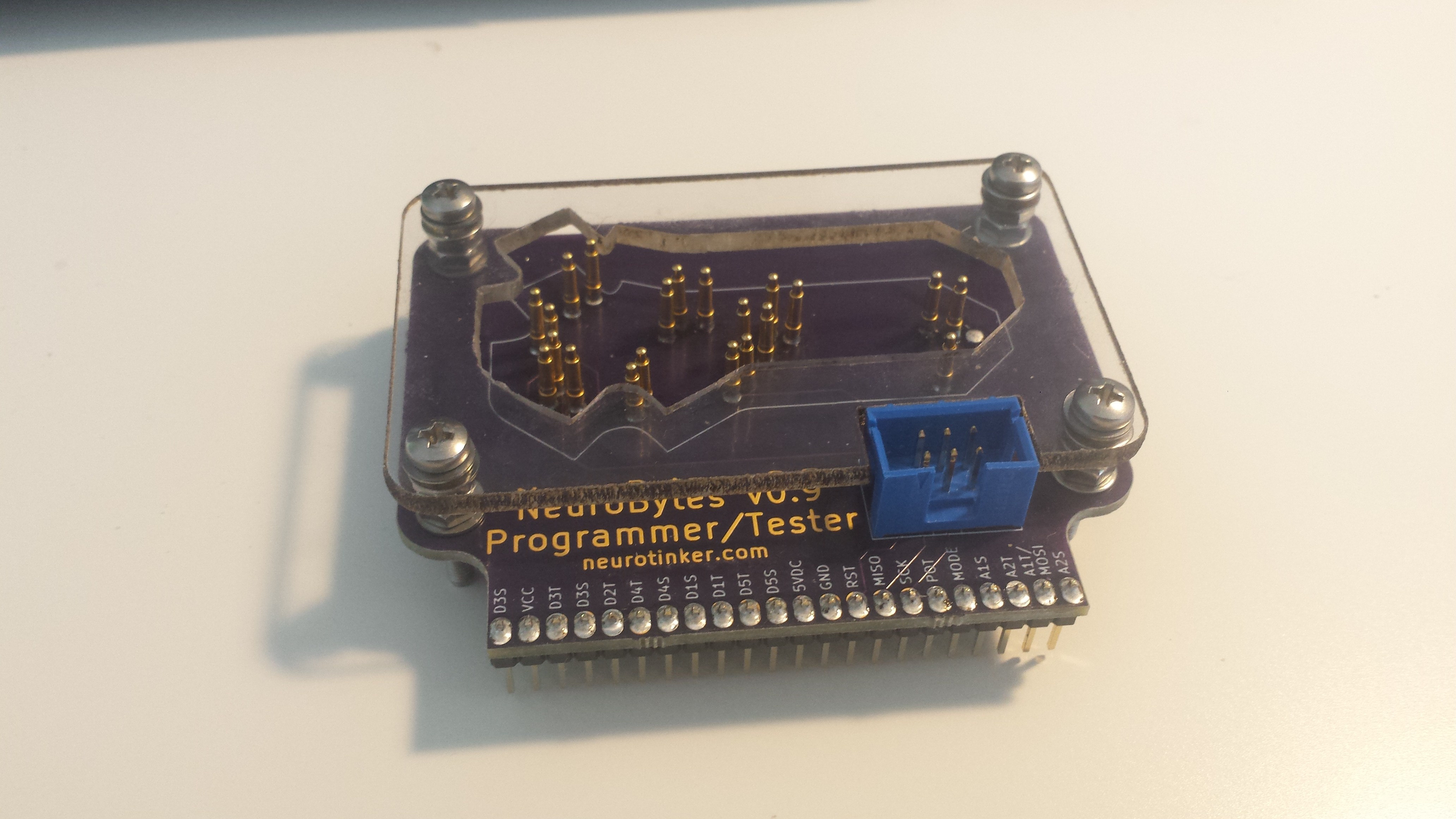
NeuroBytes v0.9 tested, programmed, and revised...
06/02/2016 at 16:47 • 0 commentsI spent the last few days building a bunch of NeuroBytes v0.9 boards. I also received my order of pogo pins in the mail, so I built the tester/programmer:
![]()
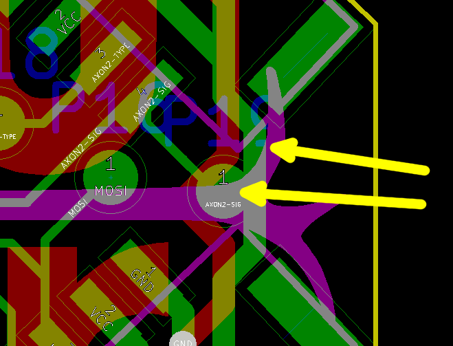
Problem One: The pogo pin on the far right side doesn't fit between the two axon connectors, so I had to remove it (hence the solder blob in the picture above). You can see how close it is on the PCB layout here:
![]()
Top arrow points to the light pink outline of the JST header; bottom arrow points to the AXON2-SIG test pad. The distance between the two is a scant 0.3 mm, which is not enough room for the shoulder of the pogo pin to clear; the tip never makes contact. Not a huge deal for programming since AXON2-SIG isn't shared with one of the ISP pins, but still something that needs to be revised.
I modified the LED test program to use the new port designations; these tend to change with each revision as the PCB layout comes together. After a bit of fiddling I got the program to light up the RGB LED at full brightness:
![]()
Problem Two: the LED hole is too small. It's not super clear in the picture above, but to my eye the 'gear nucleus' is a bit on the thick side. Not a huge deal, I just need to revert the footprint back to the v0.8 iteration.
I then modified the full v0.8 runtime program and tried loading it up. This took more tinkering, as I needed to ensure that both motor mode PWM outputs were active on the two axons, and had to track down some fussy code related to the MODE switch. All seemed well when I loaded the code up--the LED turned a nice green and all--and then...
Problem Three: one of the axon connections makes downstream NeuroBytes continuously fire, even when the upstream board is at rest. A check with the voltmeter confirms that the signal line is high all the time. And worse...
Problem Four: HEAT! After leaving the board plugged in for a few seconds, I noticed the ATtiny was starting to warm up a bit. It took time to track down the exact source; at first I assumed it was the LDO or some of the associated circuitry, but a good deal of probing narrowed down the source to the microcontroller.
![]()
NOT A TYPO--I am reusing the same picture. In this case, the top arrow points to the non-regulated VCC bus, and the bottom arrow points to the AXON2-SIG test pad. See how they overlap? Yeah, that is not supposed to be the case. That's what happens when you place components after laying traces, and then don't run a DRC. Lesson learned. Low microcontroller pin + dead short to VCC = turn ATtiny88 into an expensive resistor.
I used a razor blade to slice the pesky test pad away from the AXON2-SIG connector, and as expected both Problems Three and Four disappeared. This allowed me to score my first victory: two servos working off the same NeuroBytes board!
Far more significantly, I also spent an hour or so thoroughly testing the circuit's ability to survive hot-swapping servos. Even using much heavier duty units (the continuous rotation devices from NeuroBuggy), I didn't see a single reset event or visible LED fade. I tried 'scoping the regulated power rail and never saw more than a ~200mV sag when servos were plugged in. I also hooked a set of power wires onto an unregulated 6vdc battery pack and it worked like a charm--so I'm calling that problem solved!
As you may have expected, the victories were short-lived. I added a bit more code to read the analog potentiometer input; if you haven't used AVR-C before, it's a bit more complex than the Arduino analogRead function:
/* set up ADC */

DDRD &= ~(1<<PD6); //ensures data direction register for PD6 is set as 'input'
PRR &= ~(1<<PRADC); //ensures power reduction bit is cleared
ADCSRA |= (1<<ADEN); //enables ADC
ADCSRA |= ((1<<ADPS2) | (1<<ADPS1)); //prescales ADC clock to 125 kHz
ADCSRA |= (1<<ADSC); //starts running ADC conversion (free-running by default)
ADMUX |= (1<<ADLAR); //left justifies ADC result (just grabbing 8 MSBs)
ADMUX |= (1<<REFS0); //ensures ADC references AVcc
//note: MUX[3:0] set to 0000 by default which selects AIN0
As the comments suggest, the various registers get the ADC fired up at the proper rate (clk/64, which is 8MHz / 64 = 125 kHz), select the right channel on the mux (channel 0), and do a few other housekeeping things. But... it didn't work. My test program didn't change the LED brightness, no matter how many times I twisted the potentiometer.Why?
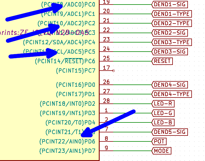
Problem Five: AIN0 is NOT an ADC channel. It's one of the inputs to the analog comparator! Yes, when I was pulling the potentiometer into the circuit I just made assumptions based on pin names rather than actually checking the appropriate section of the datasheet:
![]()
I had six [multiplexed] ADC options and I chose none of them! Yes--if I'd paid attention I might have wondered where 'AIN2' through 'AIN5' were, since I knew the ATtiny88 had 6 ADC channels. But I was in a hurry so this never crossed my mind. Ugh!
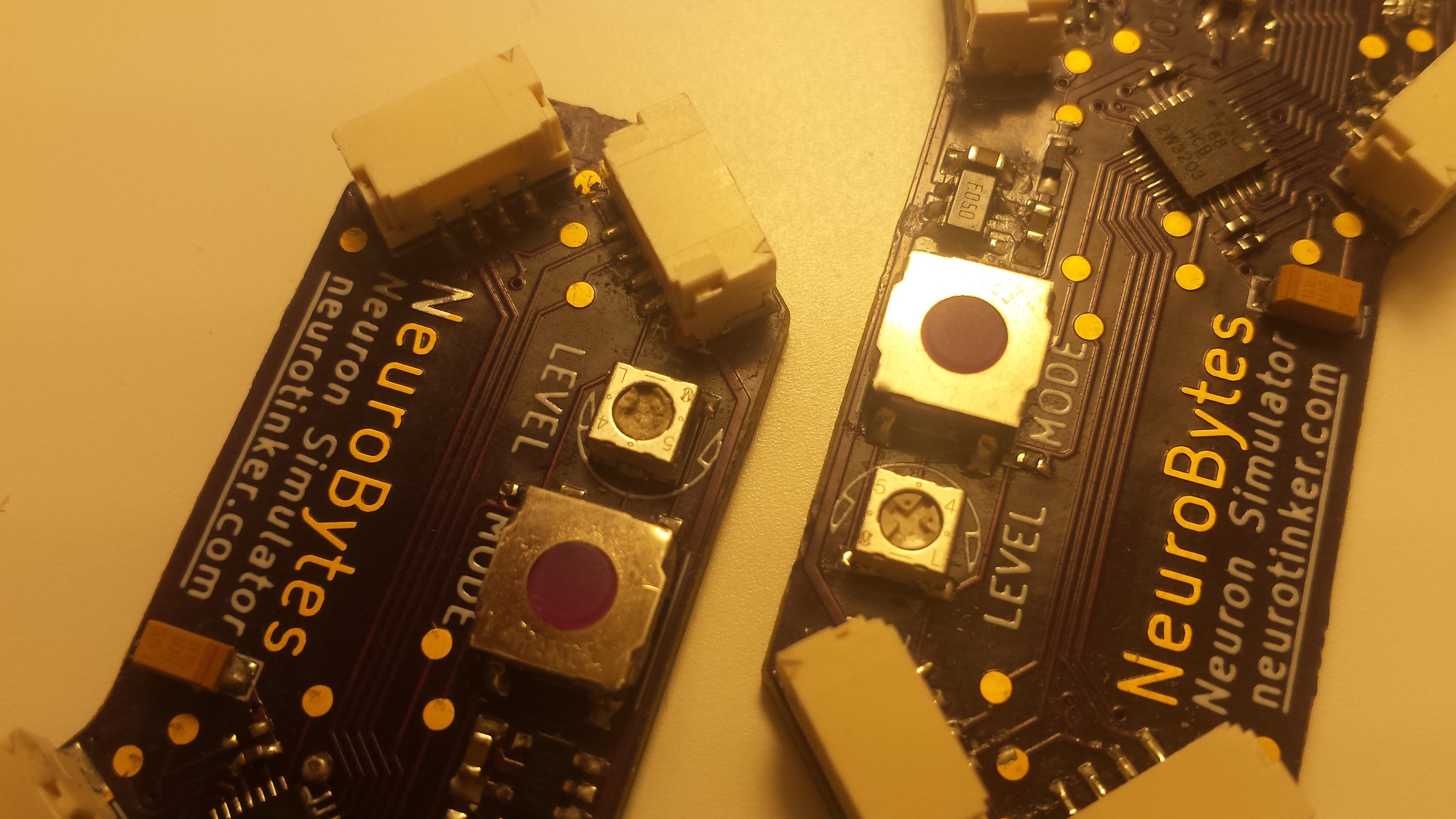
So the easy solution is to move the potentiometer to one of the six ADC channels (pins 19-24), relocating a dendrite signal or type line as needed. However, I also ran into an issue with the potentiometer itself, beyond the previously mentioned pad layout mistake and extra silkscreen:
![]()
Problem Six: it's really easy to strip the adjustment screw on the potentiometer. Okay, fine, I used a Philips head screwdriver to adjust it, which wasn't the right tool for the job, but can I really expect end users to not misplace the tiny plastic adjuster I'd need to supply with each kit?
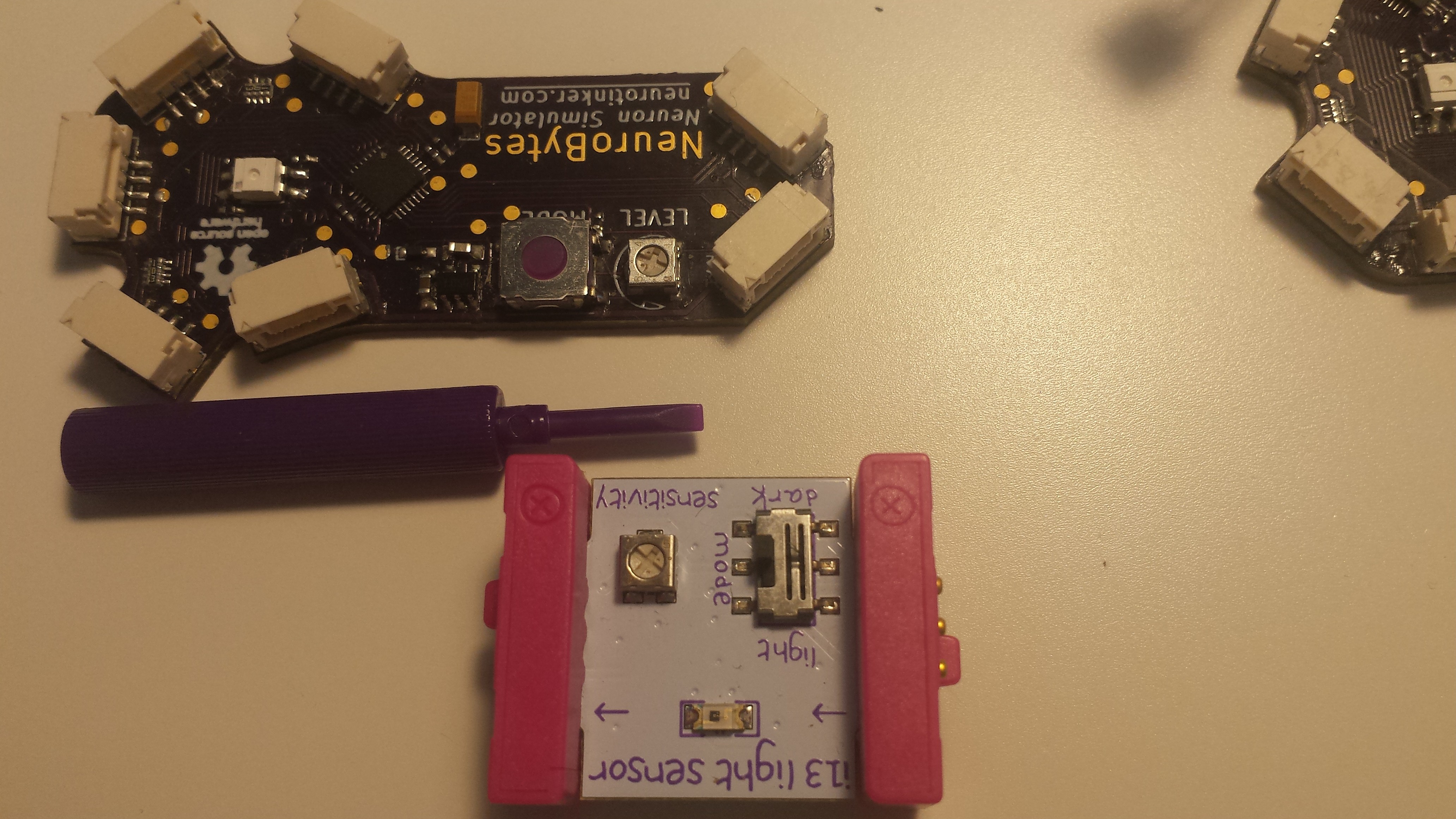
![]()
I suppose that is the strategy littleBits has adopted; as shown above, their Light Sensor Bit uses the same model potentiometer and includes a tiny purple screwdriver. But I think we're going to do something else. Stay tuned--v0.91 boards get ordered today!
-
NeuroBeast v2 walks, enables simple (and quantifiable) gait development
05/27/2016 at 16:35 • 0 commentsFirstly, the name isn't finalized. Any ideas? "NeuroBeast" is a bit lame IMHO.
Secondly, a clip of the latest iteration dragging a battery pack across the demo rug:
[Ingredients: Seventeen NeuroBytes v0.8 boards. Eight 9g servos. Eight 3D printed feet. One 3D printed chassis (single piece!). Eight 'shoes' made from cut up G3 Expedition Climbing Skins. One rechargeable cellphone battery pack. Lots of excitatory and inhibitory cables.]
Impetus
Joe and I have had a great time showing our patellar demo kit to thousands of people over the last six months: three Maker Faires, two school trials, two competitions, a number of conferences, and dozens and dozens of formal educator interviews. However, we've also realized that the setup has some inherent limitations; namely, once you understand the basic knee-jerk mechanism, the kit starts collecting dust on the shelf.
![]()
[image source: https://en.wikipedia.org/wiki/Patellar_reflex]
Our 3D printed models are a real hit at Maker Faires in particular, since we'll typically have the same 30-second conversation a few hundred times during the course of the day. But the bones aren't really modular--they only go together one way--and once you've made a few modifications (can-can line, etc), the setup stops being particularly interesting.
![DSC_0007.JPG]()
[pretty cool at first, and then boooooring.... ]
So in addition to getting v09 stuff sorted (and generally figuring out how to scale beyond toaster oven quantities), we're trying to build out new models and accessories that make the NeuroBytes ecosystem a bit more interesting for long-term engagement. Hence, NeuroBeast, or whatever we end up calling this new creature.
Design
I wanted to build a platform with a number of independently controllable legs so that one could emulate the gaits found in metameric invertebrates such as centipedes. In very general terms, these arthropods move using a metachronal rhythm, meaning the legs move in a wave-like sequence when viewed from overhead as shown in this link. This type of robot isn't particularly novel; for example, the Harvard Microrobotics Lab produced a fascinating example at a much smaller scale:
[Yup, NeuroBeast has nothing on the Centipede Millirobot, but it should allow anyone to putz around with 'pede gaits.]
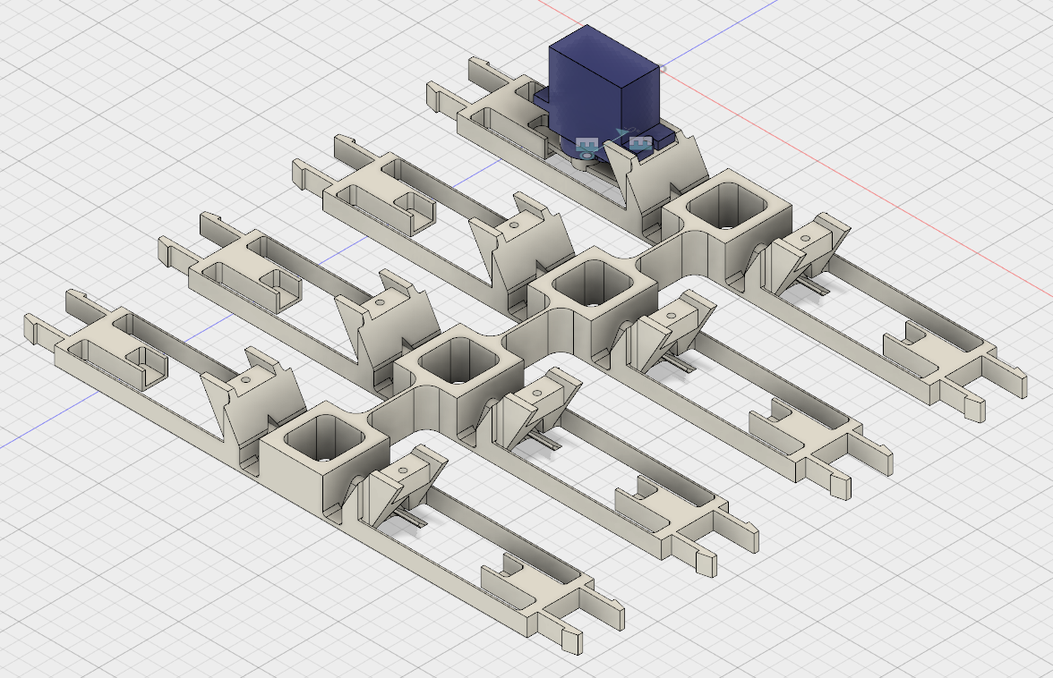
The chassis is made of a single 3D printed frame, designed to be printed in 4-5 hours with PLA and no support material on a hobby-grade setup. I used a Rostock Max with a heated build plate, but any 8" x 8" Cartesian RepRap should work too.
![]()
[Designed using Autodesk Fusion 360. Yes, I played around with FreeCAD for a solid week before switching over and the former is just not as capable or easy to use. I'm not a fan of using closed-source development tools but I'll make every effort to share this design, both in *.stl format and (hopefully) in model format. As usual, everything is released and covered under the terms of GPL v3.]
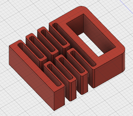
Each of the eight "legs" connects to a 3D printed "foot":
![]()
As you can see, I got really into compliant design. The feet are printed separately for two reasons: one, so that different "shoes" can be equipped to deal with different surfaces; and two, because printing the feet flat takes advantage of the filament directionality and greatly improves the consistency and printability of the springs.
The legs might be a bit tough to visualize in motion. If you look closely at the servo model that is superimposed on one of the legs, you can see that the servo is fitted with a double-sided horn. Each side of the horn handles one degree of freedom: the outbound end causes the leg to flex back and forth, while the inbound end revolves about a diagonal cam that makes the foot lift up and down:
[this video shows a single foot used for testing and iteration; getting the cam angle correct took a bit of hand-carving to get right.]
It's not a real 2-DoF setup because the two motions are inexorably linked, but the design does allow a walking gait with only one servo per leg (and thus, only one motor NeuroBytes board per leg as well). Also, it makes a super sweet clattering noise as seen in both videos (due to the servo horn scraping along the PLA ridges). Long-term durability is still an open question, but I've probably got half an hour or so on NeuroBeast v2 without any discernible cam wear or breakage.
The current "shoes" are actually a throwback to NeuroBeast v1, when I tried to build a platform that could move entirely by scootching (i.e. not lifting up its legs at all). I bought a section of climbing skin, an interesting material designed to attach to the bottom of skis and allow the user to climb mountains without taking off their skis. Climbing skins are based on seal skins that were used for the same purpose hundreds of years ago, although now skins are made of thousands of tiny, directional nylon bristles with a self-adhesive back. As you may recall from the previous iteration, NeuroBeast v1 wasn't able to get much traction relying on shoe directionality alone, but the design seems to work well on the demo rug combined with the slight foot lift exhibited by v2.
Study
As an example of the 'quantifiable gait development' I mentioned in the log title, I did a simple study comparing two neural circuits that drive NeuroBeast v2 with different patterns. From the o'l lab notebook, here is the experimental setup:
- Use 8-legged single piece frame printed 5/25/2016 plus eight red springy feet covered in rectangles of G3 Expedition Climbing Skin (~10 x 23 mm 'shoes').
- Test course is east from SW corner of demo rug, starting with all four feet aligned with a stripe on the rug.
- Ensure all eight feet cycle correctly (i.e. they all "click" over the cam instead of just sliding back and forth).
- All eight feet start at once--change the eight motor NeuroBytes to motor mode, and then insert the jumper to start the gait sequence.
- Test finishes when NeuroBeast crosses the finish mark, identified when any part of the chassis bumps into a tissue box placed over the line.
- Finish mark is 24" from start mark, as measured along rug stripe. Any offset from the rug stripe at the end of the test is also recorded (if Zach remembers before picking up the robot).
- All tests conducted using AC power from a USB adapter. Power cord is moved manually with the robot as necessary to avoid pulling on chassis.
- Power wire is always connected to the lead NeuroBytes board (i.e. the one that generates the repeating pattern).
- Two measurements will be taken:
- Time to completion
- Lateral displacement, as measured from front right foot
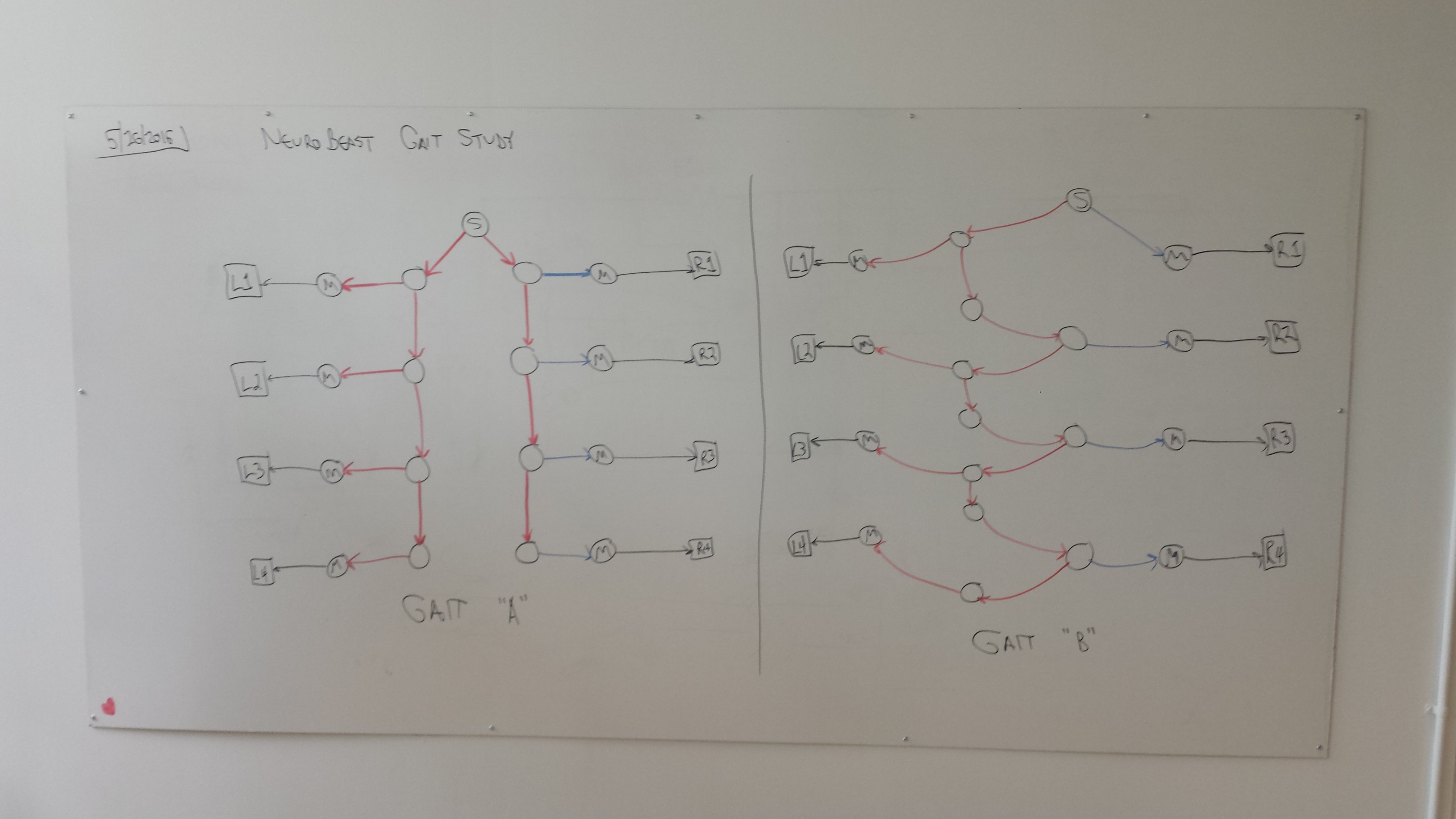
I studied two different gaits, shown in these whiteboard photos (reproduced from the notebook):
![]()
Gait A is analogous to a simplified centipede--as the first NeuroBytes board (labeled "S") sends out continuous pulses, each side sequentially actuates in parallel. Due to a software modification we made to support the patellar reflex (particularly the interneuron between the hamstring motor neuron and the sensory neuron), the inhibitory pulses have a shorter delay so the right side is a bit advanced compared to the left.
Gait B is a bit different; the pulses alternate between the left and the right side. The extra interneuron seen on the left side is mostly there because the standard stubby cables wouldn't reach without it. Due to the shorter inhibitory delay discussed above, this gait is a bit more chaotic than the first.
[note: the right side motor neurons are inhibited so the servos rotate the correct direction. This is a bit confusing since they're still really being 'excited', but it's a byproduct of the limitations of our actuators.]
And now, a video of Gait "A" on the test course, including the tissue box end marker:
My original hypothesis, as copied from my notebook:
Gait A arrives faster because the feet are closer to sync across spine (still slightly biased to right since excitatory signals are more delayed in motor mode). Gait B takes longer and arrives further off track.
And.... results:
Test Time (s) Offset (in.) B1 64.3 *** B2 66.4 -7 3/4 B3 67.6 -10 B4 66.8 -11 B5 69.3 -11 3/4 B6 65.8 -9 3/4 A1 61.x +4 1/2 A2 59.4 +7 1/2 A3 58.4 *** A4 [aborted] [aborted] A5 58.4 *** A6 57.5 *** A7 60.7 +4 1/2 A8 60.2 +5 A4 was aborted because I accidentally hit "stop" on the timer halfway through the test run. The stars in the "offset" column are me forgetting to stop the robot and measure its offset before picking it up, so that is lost data. I reset the timer on A1 before writing down the result and remembered "61", but can't recall the 10ths place so this one isn't included in calculations below. So yeah, a few data integrity issues caused by my own sloppiness, but the important thing is that I recorded it all.
Gait Time avg (s) +/- stdev Offset avg (s) +/- stdev A 59.1 +/- 1.2 s 5.5 +/- 1.5 in. B 66.7 +/- 1.5 s -10 +/- 1.5 in. So--in this limited test, there was a significant difference between the two gaits, both in terms of course completion time and typical deviation from the line. A few thoughts I jotted down yesterday (marked "concerns"):
- Do all eight feet actually click every time?
- Is the rug actually flat?
- Start angle accuracy?
- Timer start/stop accuracy? (I estimate +/- 0.5s on this alone, if not more; I was using my Galaxy S4)
- End measurement accuracy?
- Rug line angle accuracy?
- Do the feet, compliant joints, servos, etc. change over time?
- Despite attempts to minimize this, did power cord tension have any effect?
- Did the stiffness of the NeuroBytes cables themselves affect anything, since these linked the various compliant elements of the chassis?
- [this thought from today] Is Gait B slower because it uses a few extra interneurons?
Clearly more tests with more iterations of each are needed before drawing any real conclusions about the effects of the neural architecture on gait effectiveness. Having said that, this was still a fun exploration!
 Above and below: Many important changes. For starters, I located a nylon rivet on McMaster that _precisely_ fits the two holes in the battery pack, and is sized right for 1/16" FR4. The rivets are incredibly secure and allowed me to expand the circuit board quite a bit. Secondly, I inset the JST GH connectors a bit; when cables aren't plugged in, they're somewhat protected by the board overhang and are less likely to break off if the battery pack is stored loose in a box. Thirdly, I included test switches for each power jack (along with the now-required resistor divider to avoid sending 6vdc to the ATtiny), greatly improving the usability of the battery pack--now it can fully control a connected central pattern generator circuit. Finally, the pair of stick-on polyurethane bumpers prevent the switches from breaking off. We'll see how well they stay adhered; this power supply is going to get the shoulder bag pocket treatment as a real stress test.