zakqwy
-
NeuroBeast v1 barely moves, is still somewhat cool.
05/23/2016 at 15:47 • 0 commentsMore deets to come. Needs segmentation/more articulation. Funny to watch.
-
v0.9 built, but not yet tested.
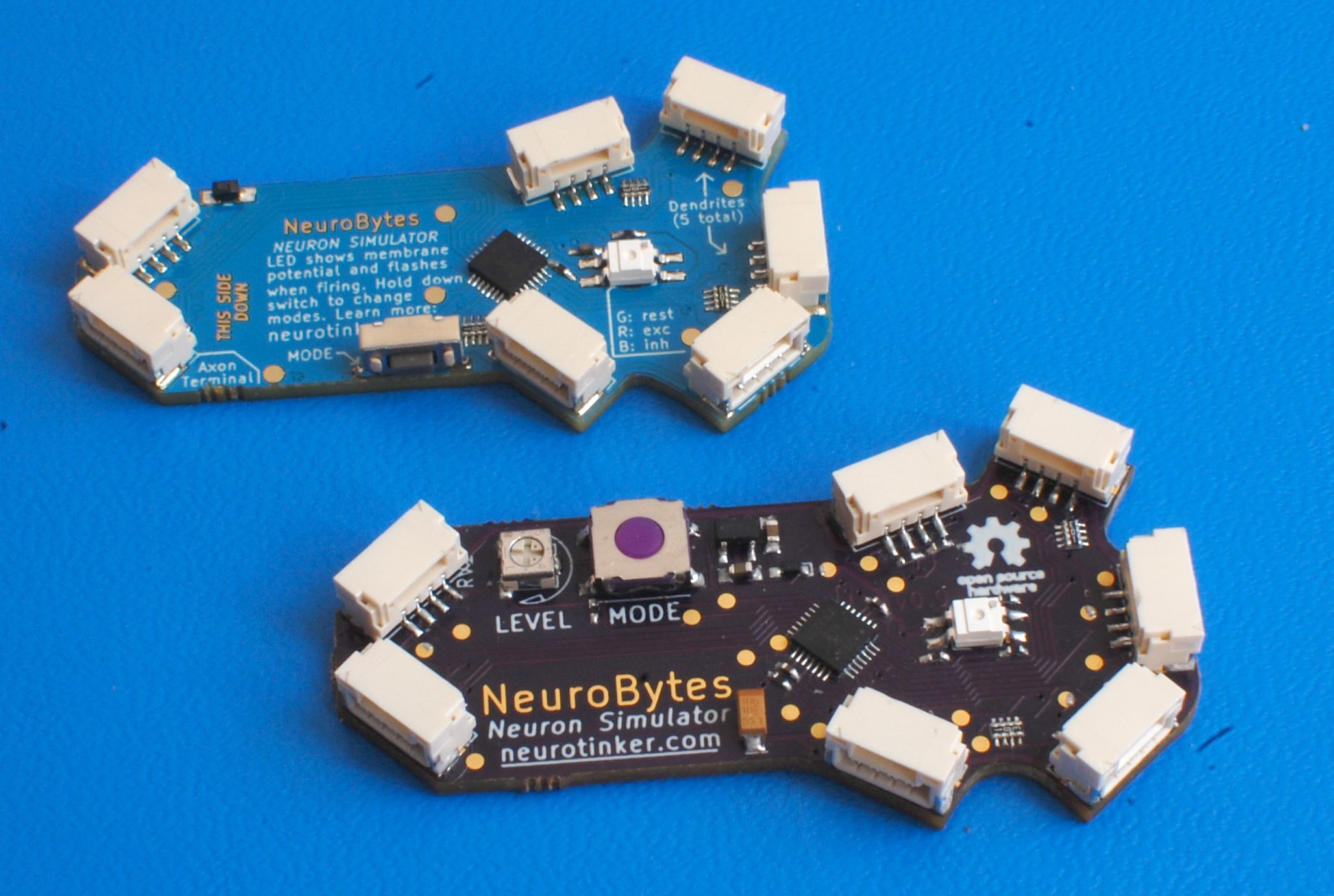
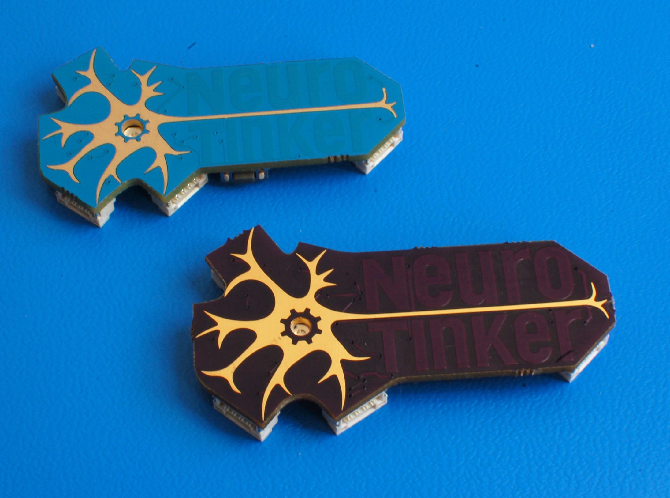
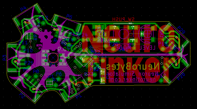
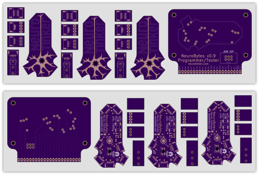
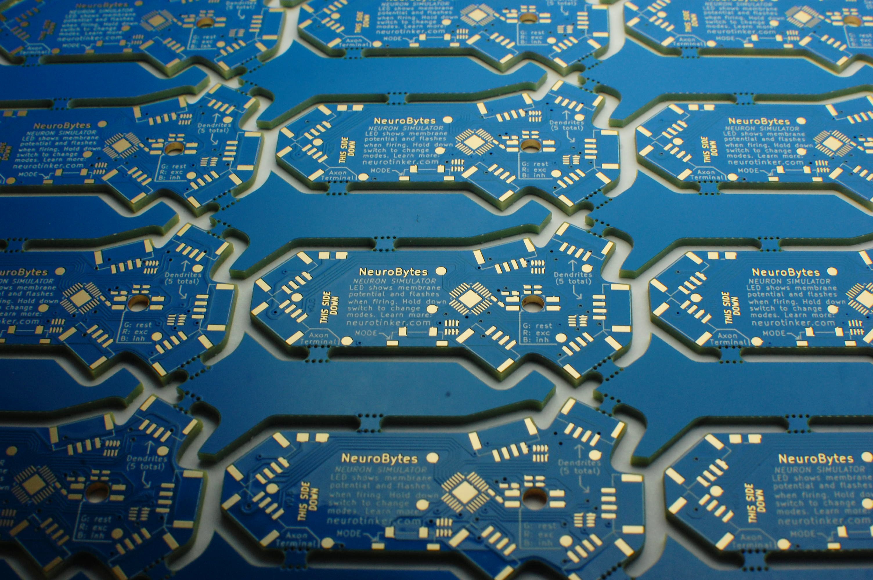
05/21/2016 at 22:09 • 0 commentsNot tested... because I forgot to order pogo pins. Still, the boards do look good:
![]()
![]()
The boards showed up from the kindly folks at @oshpark in five days! Much Excellent.
See the previous log for a complete list of changes. Stuff I need to tweak based on a first look:
- potentiometer footprint is a bit wide
- potentiometer designator accidentally left on silkscreen (RV1)
- OSHW logo text fuzzy
We'll see how it all shakes out when I start testing the board. In the meantime, the extra components did blow the BOM price up a bit, but they also add a bit of much-needed color and variety to the board which I enjoy. Anyone have a line on cheap sealed trimmers?
-
NeuroBytes v0.9 Boards Ordered. Design files released.
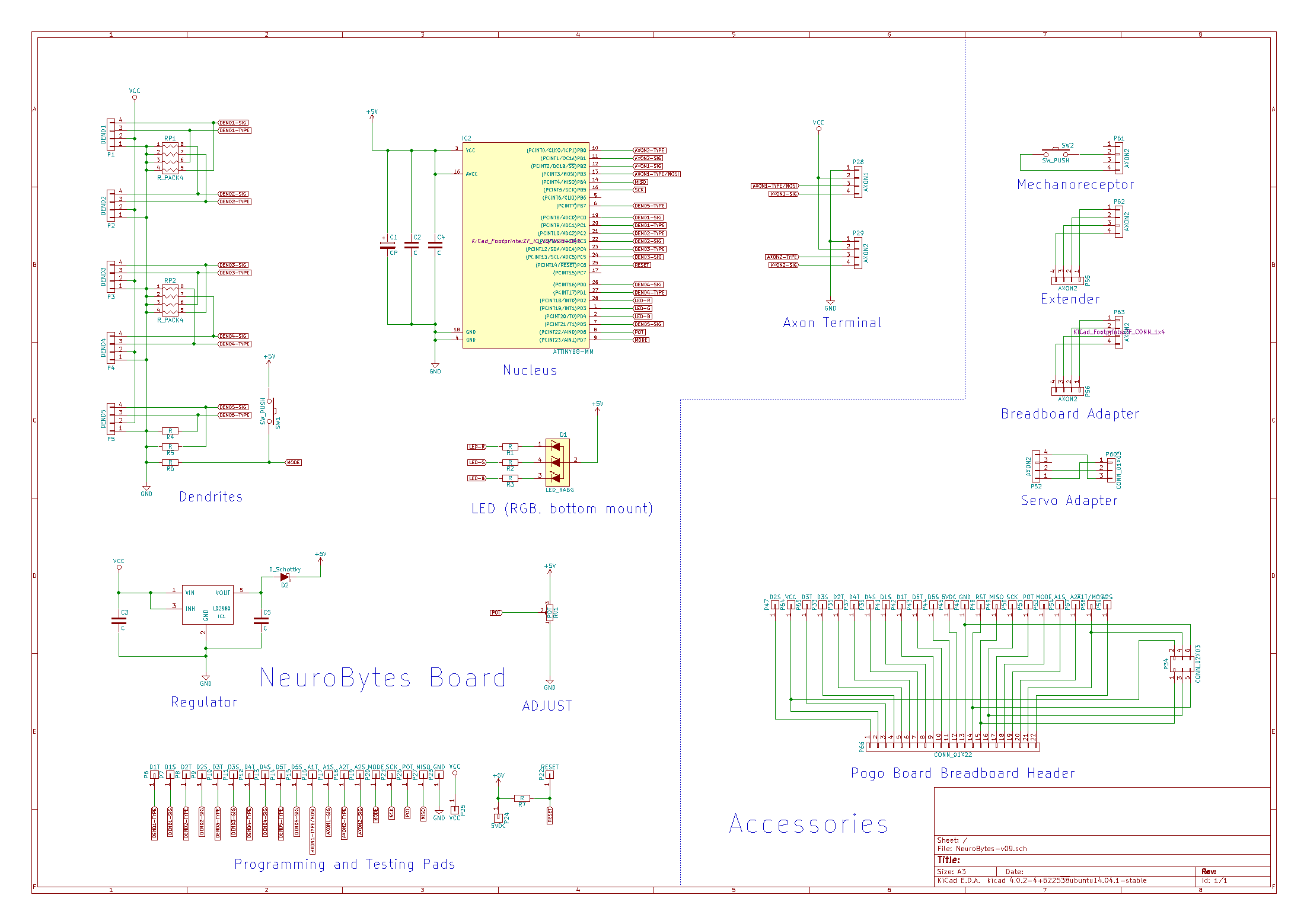
05/15/2016 at 20:20 • 0 commentsFirst: I just placed the order for NeuroBytes v0.9 boards. Super Speedy Service plus overnight delivery, so with luck @oshpark will have them to Minneapolis this coming week!
![]()
![]()
Full order, including a few breakout/accessory boards and a programmer/tester:
![]()
Changes vs v0.9:
- Added on-board potentiometer
- Made ends parallel so I can v-score the boards (along with some routing) in production
- Both axon signals now route to hardware PWM-capable pins
- Added on-board LDO and associated capacitors
- Added Schottky diode on microcontroller voltage rail
- Added OSHW logo to silkscreen
- Reduced LED hole size slightly
- Added pogo pads for testing axons, dendrites, etc.
- Changed MODE switch to standard type (vs right-angle)
- General silkscreen improvements/simplifications
- Probably some other stuff too.
Second: I uploaded the complete v0.9 hardware design files. As with the v0.4 release, everything is covered by GPL v3. If you do decide to make your own NeuroBytes, keep in mind that the current boards are currently untested and should be considered prototypes. Let me know if you have an issue viewing these documents!
-
Shoulders of Giants
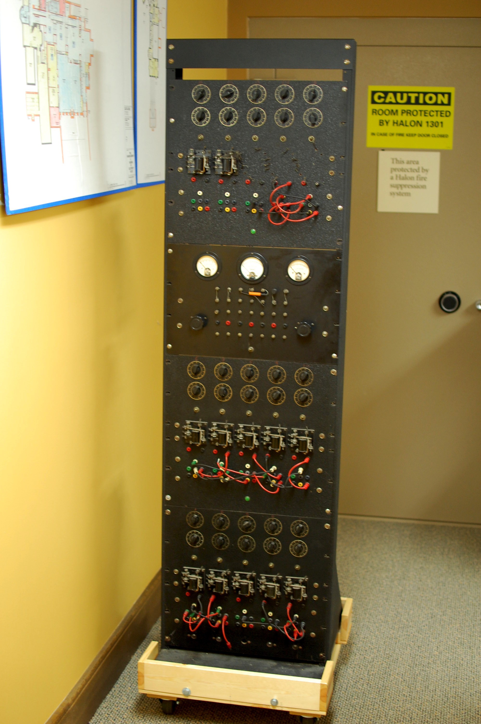
05/10/2016 at 17:41 • 0 commentsYesterday afternoon, I stopped by the Bakken Museum and had the privilege of spending a few hours with this fascinating device:
![]()
[Image Credit: Schmitt Trigger Nerve Computer, catalog # 85.014.001, courtesy of The Bakken Museum, Minneapolis, MN.]
As the caption suggests, this is the original nerve computer Otto Schmitt built in 1937 for his PhD thesis at Washington University:
![]()
[Image Credit: Schmitt Trigger Nerve Computer, catalog # 85.014.001, courtesy of The Bakken Museum, Minneapolis, MN.]
Yup, Dr. Otto Schmitt, the gentleman that developed the Schmitt Trigger. Which, by the way, was first used in this machine. The Nerve Computer is a really important artifact: in addition to being the first biological neuron simulator, its direct descendants include pretty much every computer ever built.
I learned of the Nerve Computer's existence a few months ago and got in touch with the curator at the Bakken; he was intrigued enough by the NeuroBytes project that he let me give the device a thorough examination. I didn't have great lighting but I did manage to snap a few pictures of the 80-year-old circuitry.
[Image Credit: Schmitt Trigger Nerve Computer, catalog # 85.014.001, courtesy of The Bakken Museum, Minneapolis, MN.]![]()
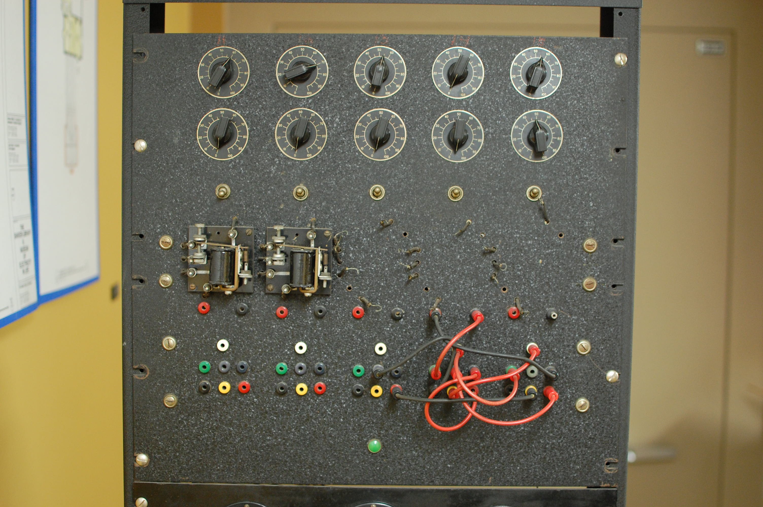
The Nerve Computer used fifteen identical circuits to simulate a nerve using a model based around capacitors, along with a series of switches for polarizing and depolarizing a cell membrane. The system was designed to be flexible; several different capacitors could be selected to alter the system's response, allowing researchers to accurately reproduce previously observed nerve signals.
![]()
[Image Credit: Schmitt Trigger Nerve Computer, catalog # 85.014.001, courtesy of The Bakken Museum, Minneapolis, MN.]
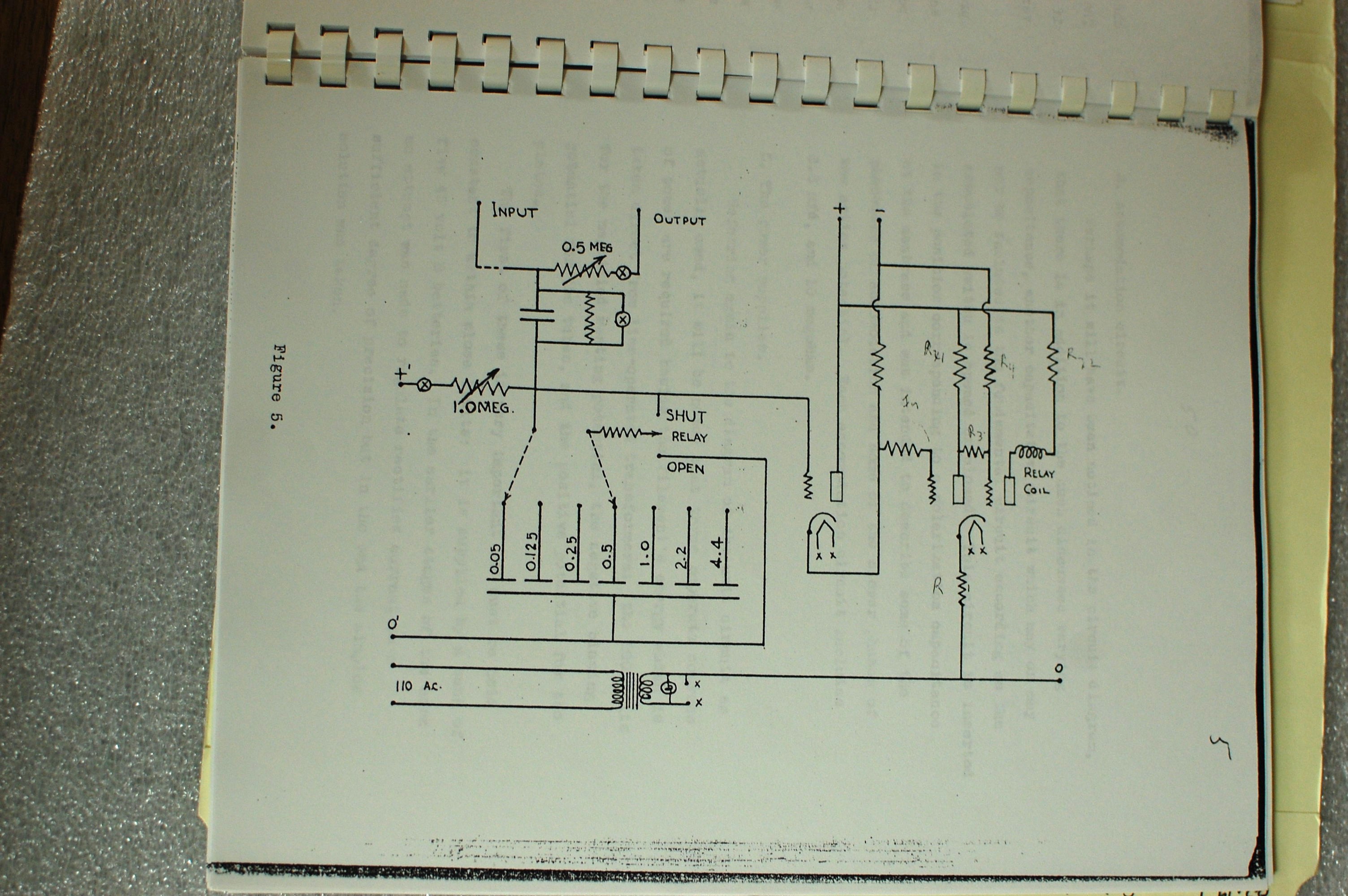
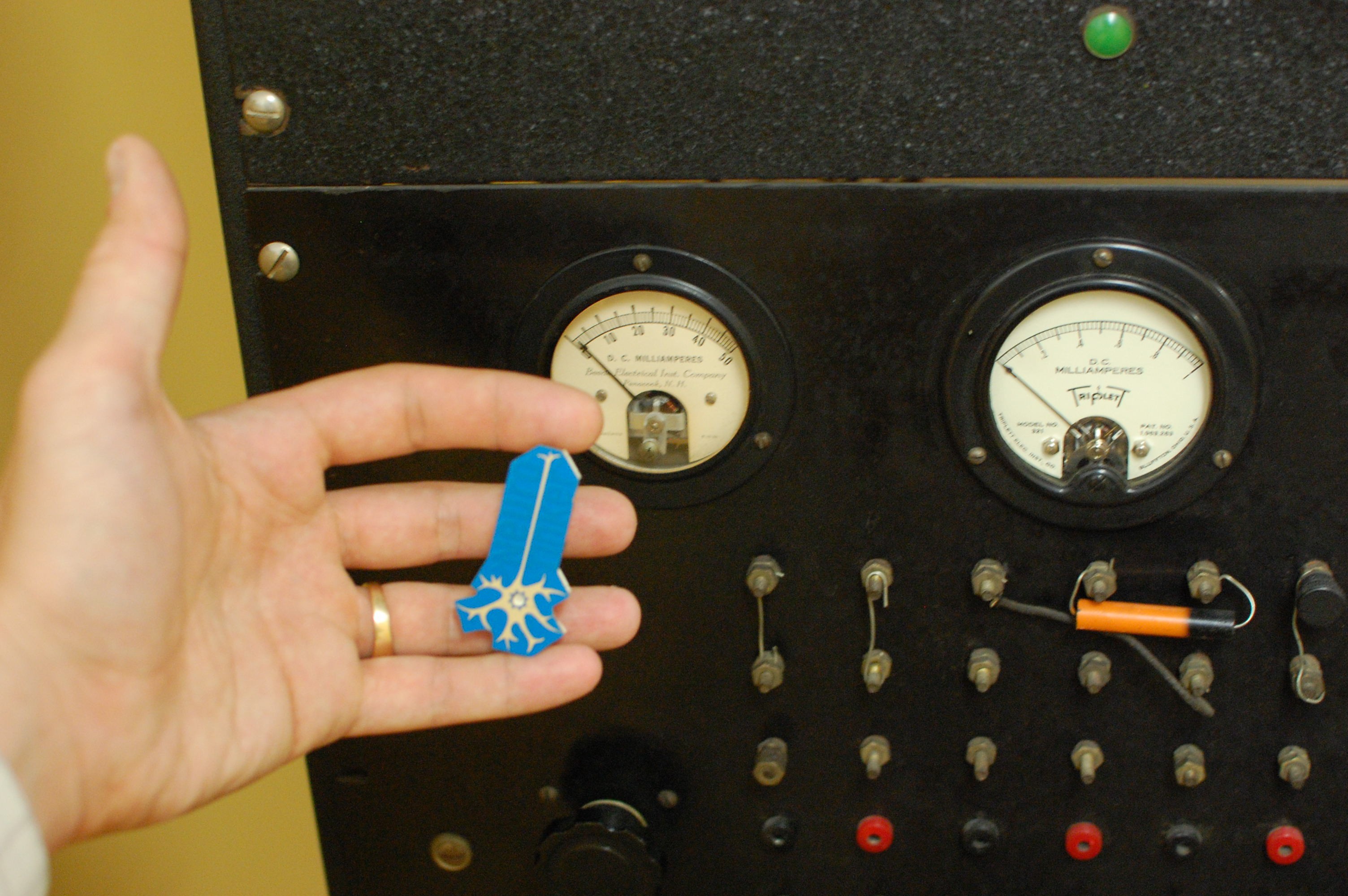
I didn't have time to read through all of Dr. Schmitt's thesis, but I was able to find a few interesting tidbits of information. For example, his calculations suggested that larger value capacitors could have been valuable to the simulation; however, he found that any devices over 8 microfarads were prohibitively expensive. He also wanted to work at a biological voltage scale (which involves tens of millivolts) but didn't want to use amplifiers, as they may introduce too much noise into the system. Instead, he just designed the system to operate at three orders of magnitude above the biological levels, so the entire system ran at a few hundred volts. I suppose that's one of many reasons the museum doesn't power the rack up.
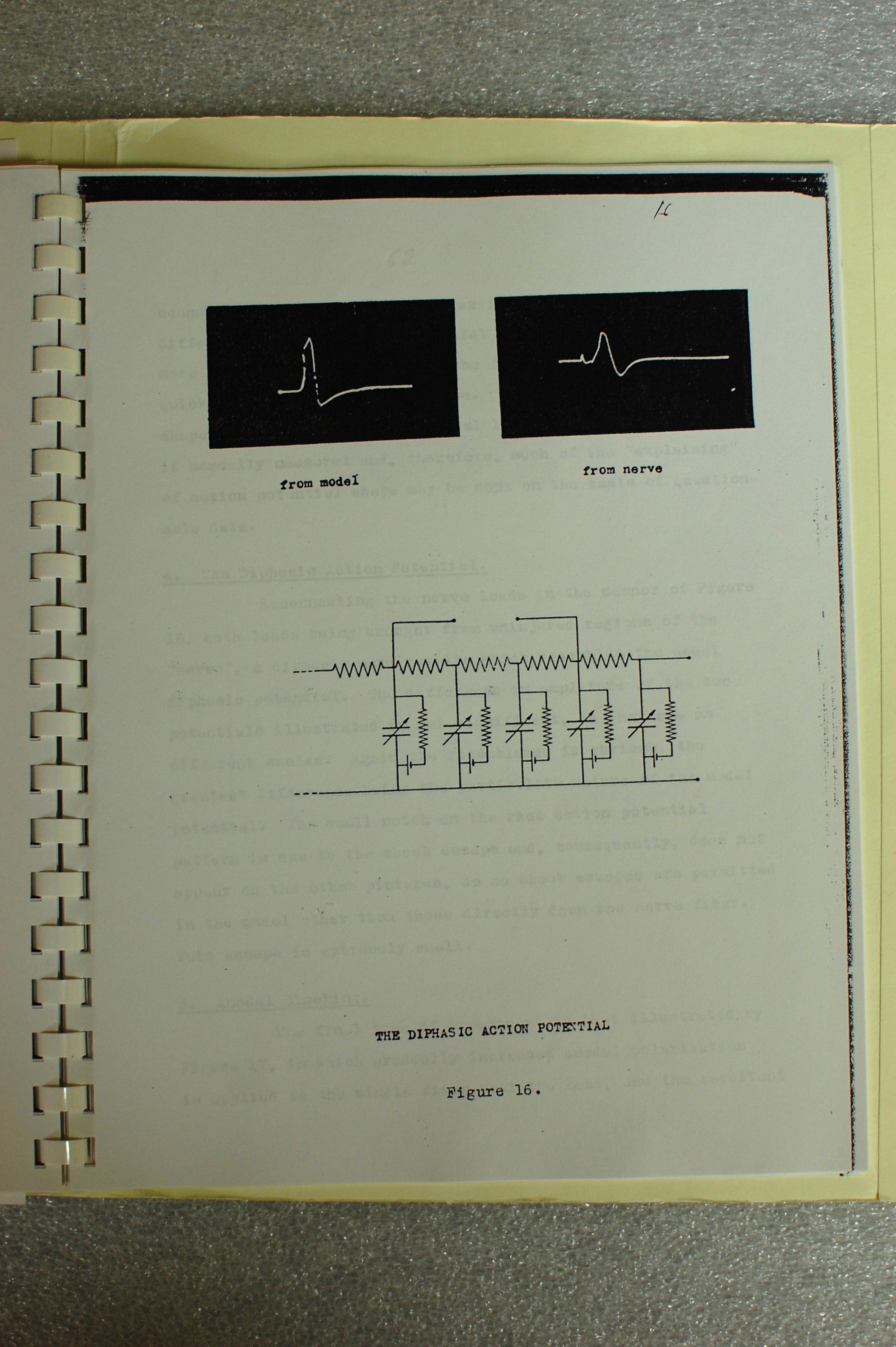
The original apparatus included a built-in 5" CRT oscilloscope which was lost prior to the museum's acquisition of the computer in 1985. Dr. Schmitt used long-exposure photographs to capture action potential waveforms (a tedious procedure involving glass plates and a great deal of dexterity) generated by the rack and by real axons under study, and was able to adjust the component values on the simulator to line up well with the biological examples:
![]()
[Image Credit: Schmitt Trigger Nerve Computer, catalog # 85.014.001, courtesy of The Bakken Museum, Minneapolis, MN.]
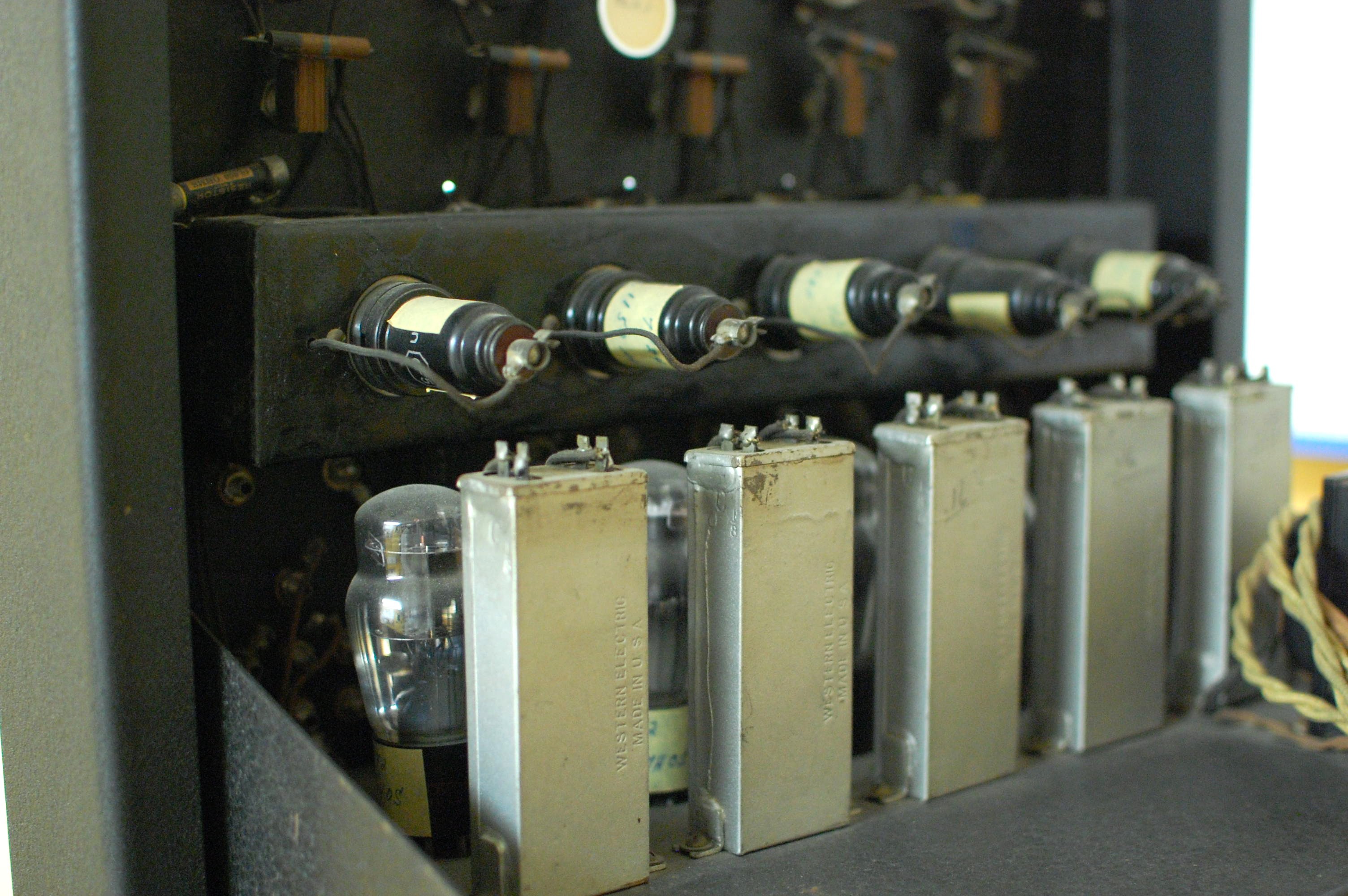
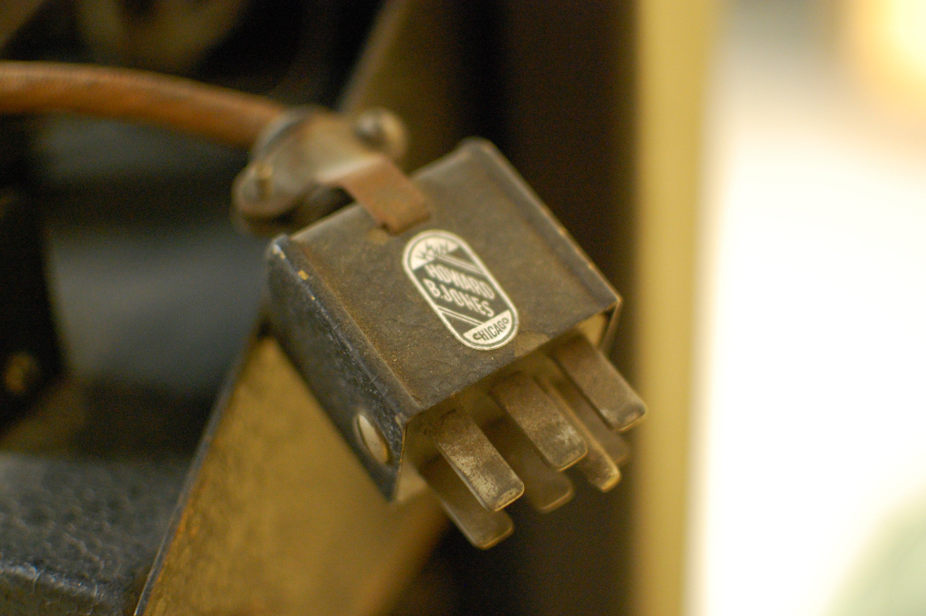
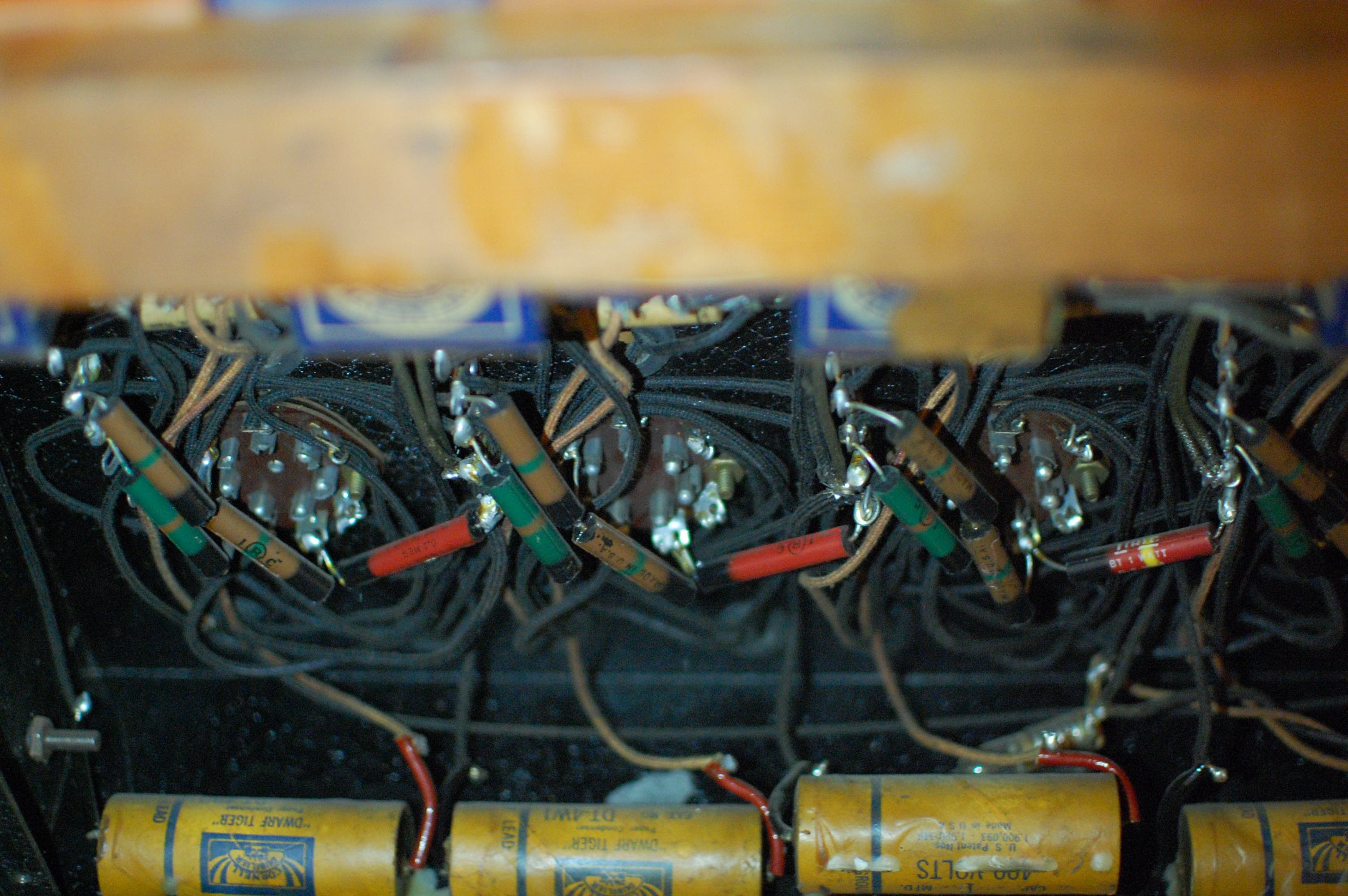
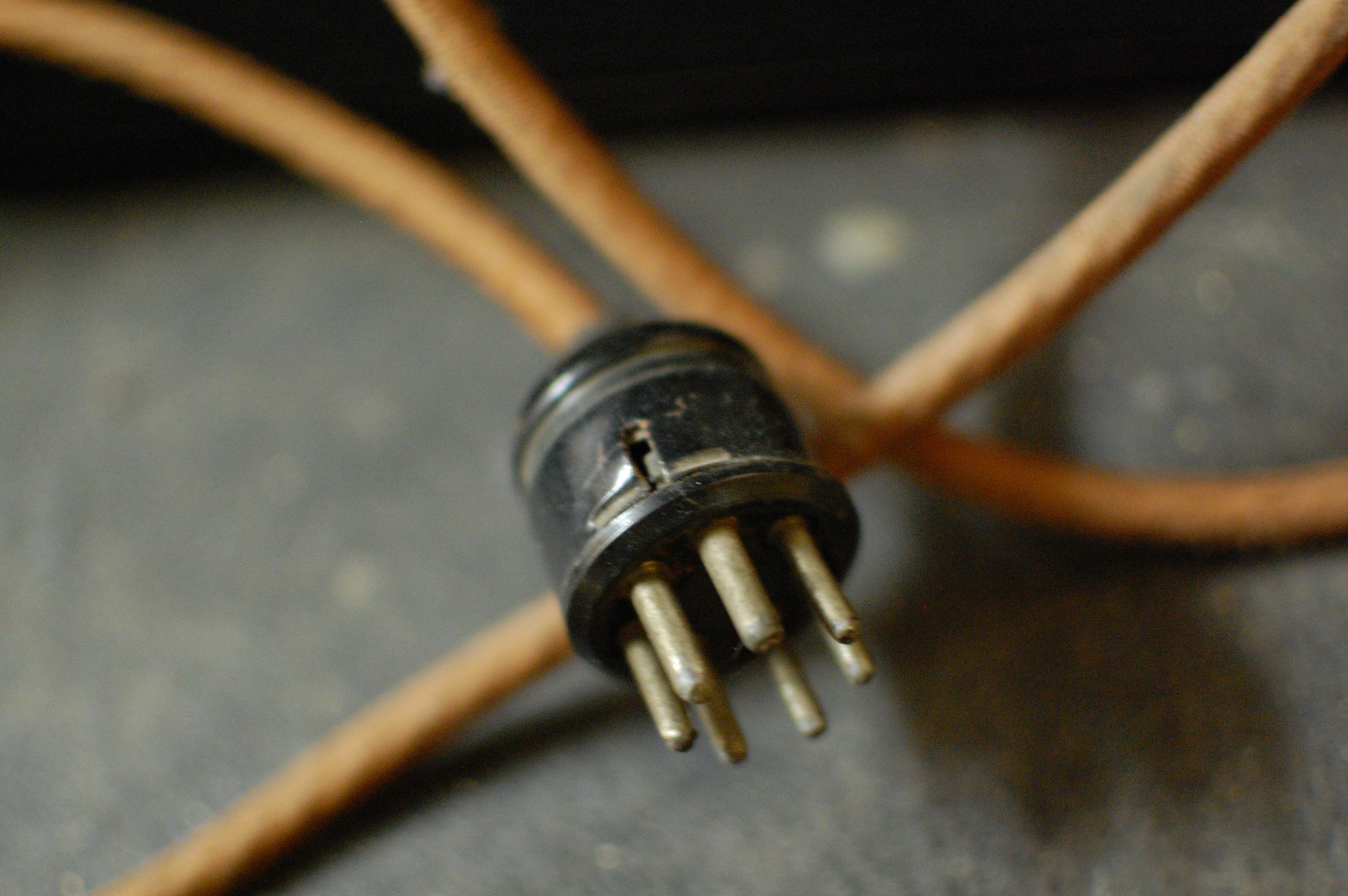
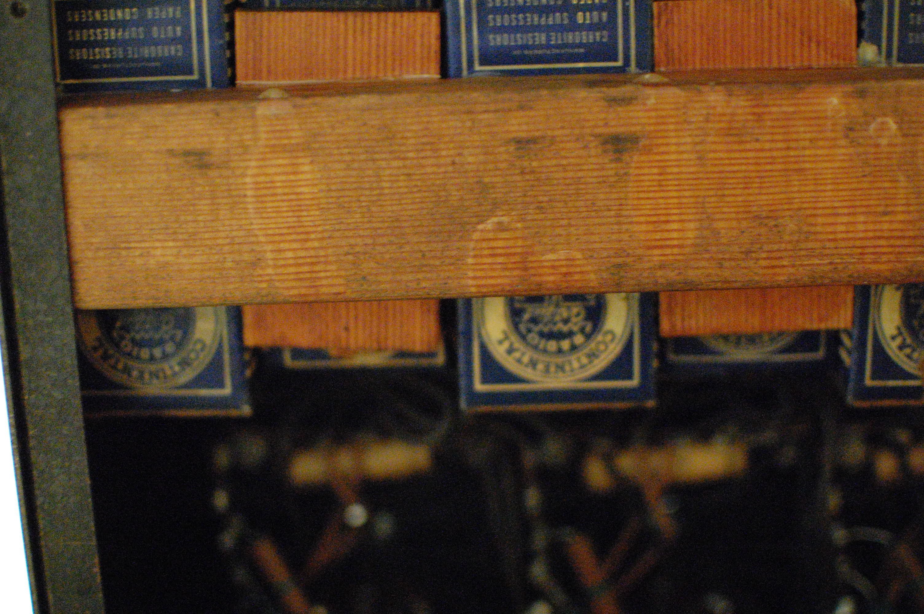
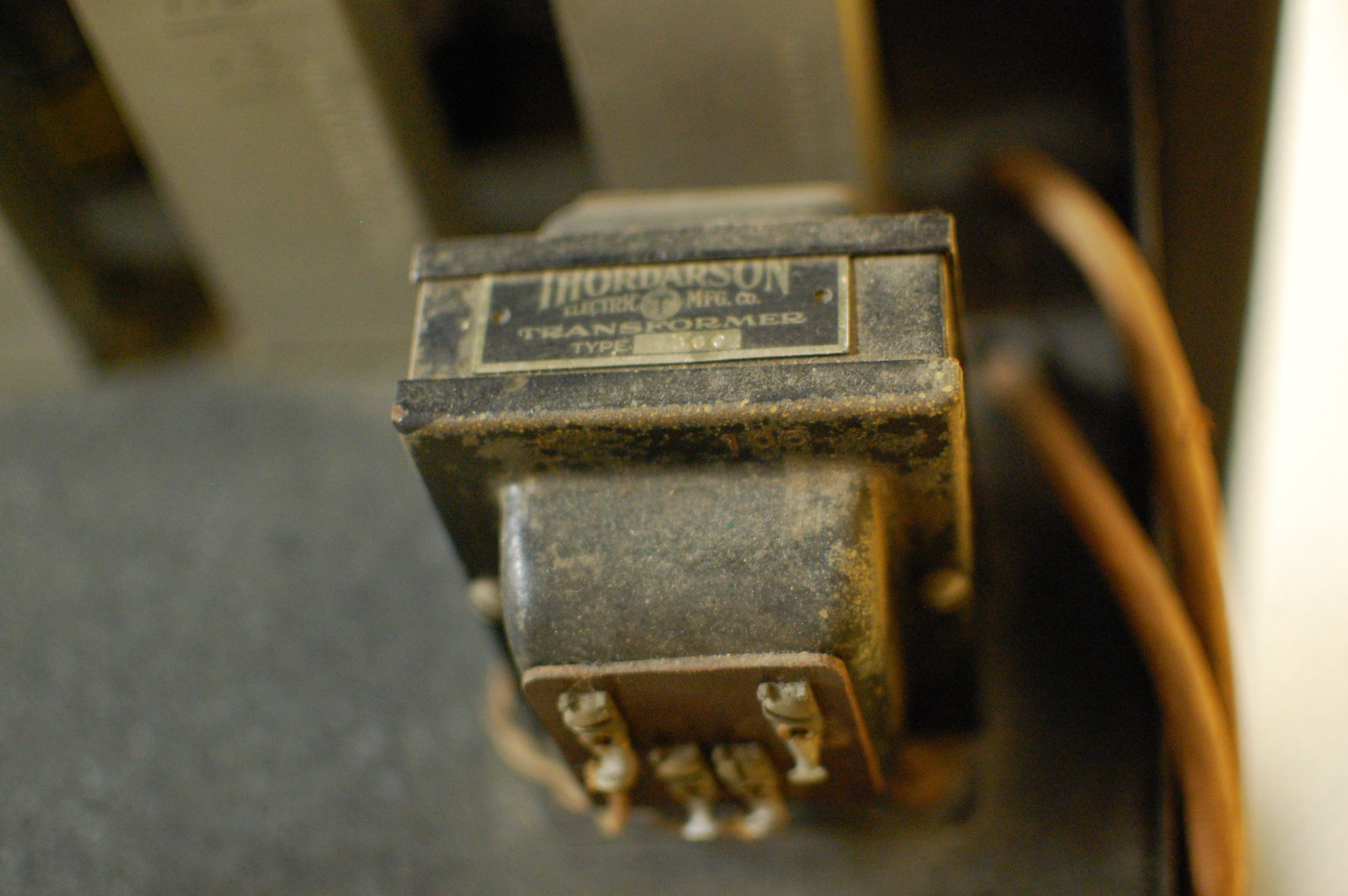
One thing I really enjoyed about the Nerve Computer was seeing all of the ancient components. I didn't recognize any of the brands (such as Dwarf Tiger capacitors), but I did manage to capture a few photos:
![]()
[Image Credit: Schmitt Trigger Nerve Computer, catalog # 85.014.001, courtesy of The Bakken Museum, Minneapolis, MN.]
![]()
[Image Credit: Schmitt Trigger Nerve Computer, catalog # 85.014.001, courtesy of The Bakken Museum, Minneapolis, MN.]
![]()
[Image Credit: Schmitt Trigger Nerve Computer, catalog # 85.014.001, courtesy of The Bakken Museum, Minneapolis, MN.]
![]()
[Image Credit: Schmitt Trigger Nerve Computer, catalog # 85.014.001, courtesy of The Bakken Museum, Minneapolis, MN.]
![]()
[Image Credit: Schmitt Trigger Nerve Computer, catalog # 85.014.001, courtesy of The Bakken Museum, Minneapolis, MN.]
Again... apologies for the somewhat blurry and grainy pictures. Some of 'em are ISO 1600, F/1.8, 1/30 second handheld exposures to deal with the low light, which isn't ideal for detail work. And yes--the cardboard boxes along the wooden support are capacitors. Also, three of the awesome open-frame relays were apparently "borrowed" while the rack sat outside Dr. Schmitt's lab at the U of M:![]() [Image Credit: Schmitt Trigger Nerve Computer, catalog # 85.014.001, courtesy of The Bakken Museum, Minneapolis, MN.]
[Image Credit: Schmitt Trigger Nerve Computer, catalog # 85.014.001, courtesy of The Bakken Museum, Minneapolis, MN.]Yup, pretty much an amazing Monday. As suggested in the post title, the Schmitt Nerve Computer is the first in an 80-year line of electrical/electronic neuron simulators (some of the others are linked in the sidebar). The device is NeuroBytes' great-great-great grandparent, so I figured a quick family portrait was in order:
![]() [Image Credit: Schmitt Trigger Nerve Computer, catalog # 85.014.001, courtesy of The Bakken Museum, Minneapolis, MN.]
[Image Credit: Schmitt Trigger Nerve Computer, catalog # 85.014.001, courtesy of The Bakken Museum, Minneapolis, MN.]In other news, if you happen to be anywhere near Minneapolis... make sure you spend a few hours at the Bakken!
-
Dealing with pesky servo-induced brownouts
05/06/2016 at 14:03 • 7 commentsWe're on the other side of our two trials--UW-W and PHHS--and by all accounts they were fantastic. We did a pre- and post-test for each session to try to gauge learning gains, and included a large section for free form comments. Data is still getting crunched, but the comments were overwhelmingly positive, especially from the high school crew. Success!
One significant learning, however, was that microcontroller brownouts caused by hot-swapping the servos were pretty frustrating. The students thought it was a bit funny that the solution was to cycle the power ("omg that actually works!"), but the condition is clearly not acceptable for a final product.
Above: Re-inserting the servo connector causes the LED to extinguish, go into bizarre super-bright mode, and then reset to the normal state. Not a good sign.
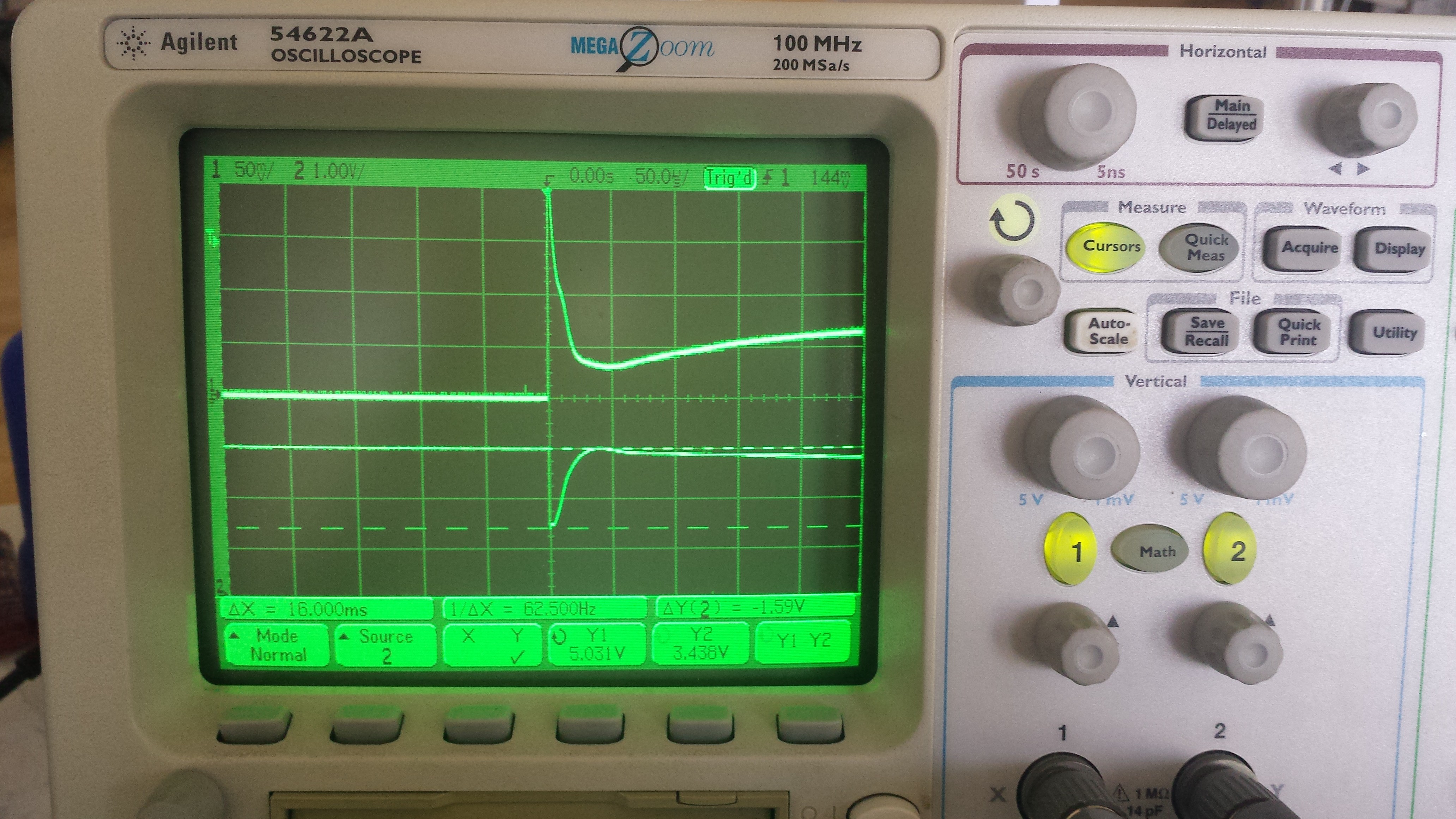
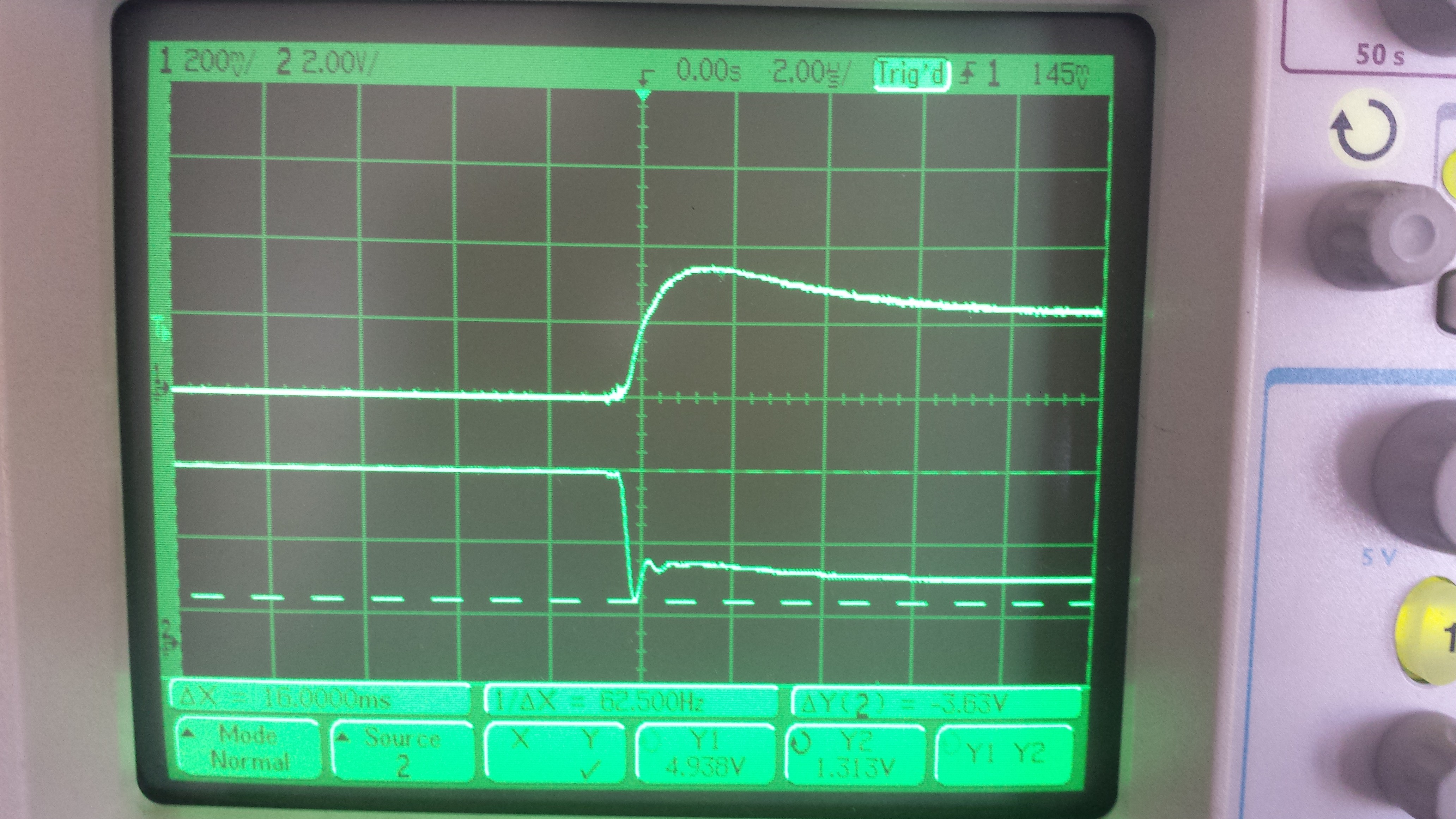
I ran the power lead through a 0.1 ohm shunt and plotted current (channel 1) and bus voltage (channel 2) at the moment of connection:
![]()
Above: The current draw spike and corresponding voltage bus sag caused by connecting a servo. The voltage rail typically dips to 3.5 VDC or so, easily sufficient to brownout the ATtiny88.
Using Dave's excellent lexicon, the hacky solution would be to 'whack a bunch of capacitors on the output'. Before doing this, I wanted to quantify the amount of capacitance really needed to absorb the complete servo power-up demand. Starting with the basic equation, where C is capacitance in Farads and q is charge in coulombs:
Charge is the total current flow integrated over the time period in question:
So. I believe this means that I can integrate the current curve over time, then divide by the maximum acceptable voltage drop--say, 0.5 VDC--to get a reasonable first pass at the total ideal capacitor value I'd need to minimize voltage rail sag. The 'scope has an integration math function, and integrating the current trace until it falls back to near zero (which takes a good bit longer than the screenshot above suggests) yielded 21.9 mA*s, so...
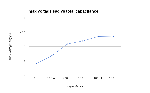
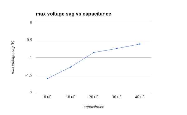
Calling my EE knowledge rusty would be an understatement, so any comments are appreciated here. In any case, I ran a few tests with a bunch of different caps and found the above value to work using a bunch of parallel aluminum electrolytics I had lying around (all values averaged over five tests):
![]()
So... close, but not quite 0.5 volts. And yes, I did try ganging more capacitors together but still hit a wall at ~0.6V sag:
![]()
For what it's worth the microcontroller never browned out under these conditions, but I wanted to avoid using a ton of big electrolytic capacitors if possible. I took a look at littleBits' open-source servo adapter schematic, assuming they're interested in enabling hot-swapping too, and noticed a 47 uF polarized capacitor across the servo terminals. I also located a Youtube video that showed the back of the adapter and noticed that it was a tantalum unit, presumably for longer life and lower ESR. Looks like they're less worried about the entire length of the sag and more concerned about the initial spike... interesting!
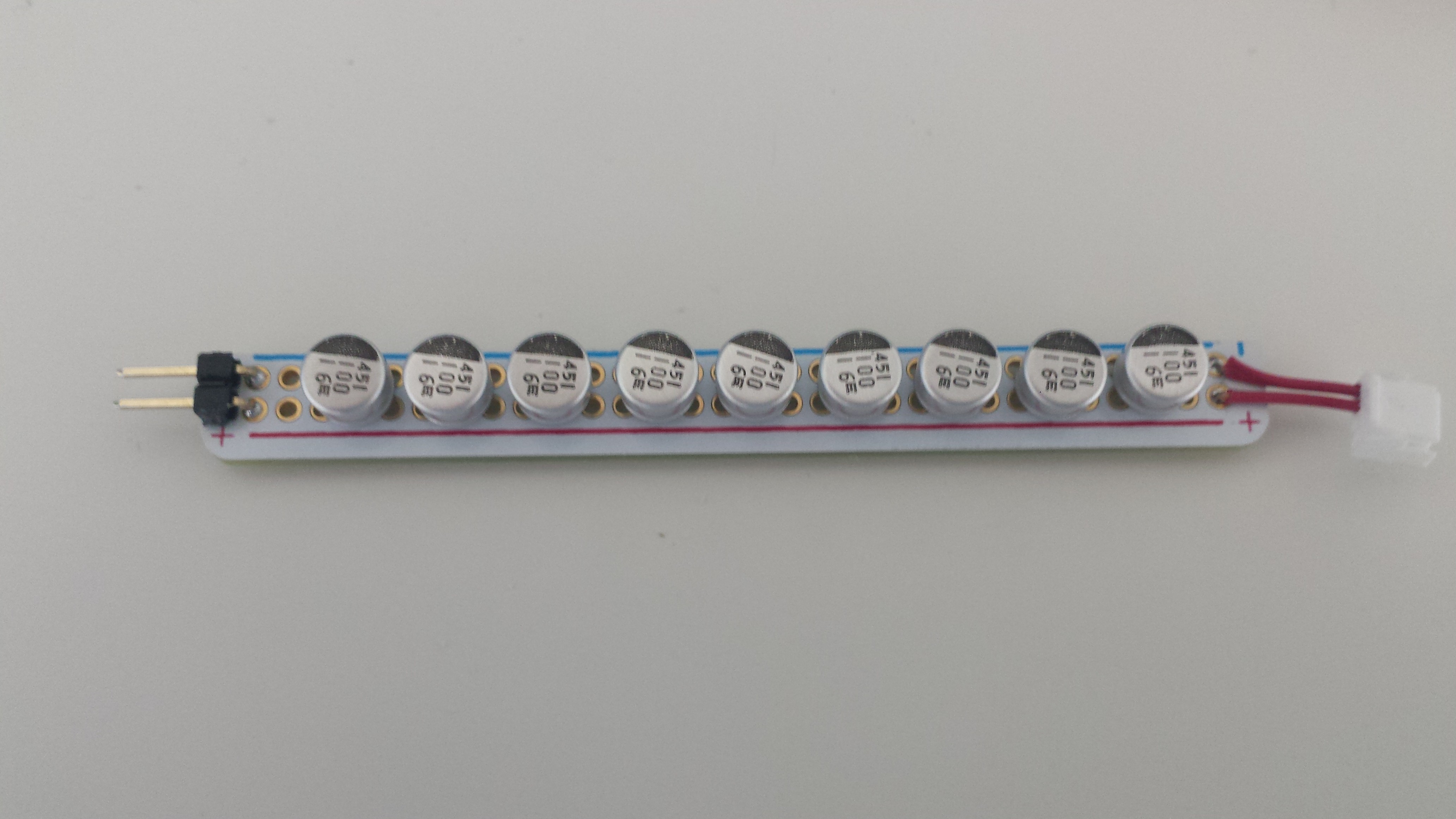
More testing. I didn't have any 47 uF tantalum caps, but I did have a bunch of 10 uF units that I started paralleling together to see how they'd effect the circuit:
![]()
[Sharp eyes will notice that I desoldered the 10 uF tantalum unit from the NeuroBytes board for testing...]
Results were promising:
![]()
I didn't plot beyond four parallel capacitors, but I did test the NeuroBytes board with nine just to see what would happen; the ridiculously low ESR of the cap bank allowed the servo to draw an instantaneous current of 6 amps on startup!
Okay, great! Problem is solved. Only it isn't... I don't want to add a 47 uF tantalum capacitor to each NeuroBytes board. Why? Well.. look what happens when I plug in the 90 uF bank, instead of leaving it connected and hot-swapping the servo:
![]()
Note the revised scale for channel 2; if you can't read the cursor at the bottom, it shows the voltage rail sagging to 1.3 volts for a few hundred nanoseconds, then staying below 2.5 volts for the rest of the screen. As expected, the microcontroller didn't like this!
Here's the issue: if I put such a capacitor on each NeuroBytes board, there's a chance that connecting new boards will cause upstream boards to reset by sagging the power rail while their reservoir caps charge. This basically pushes the problem upstream--once the boards are all powered one could hot-swap the servo (as the charged cap would handle the sag), but new boards would cause resets! It's super frustrating when you build a big neural circuit and suddenly LEDs start doing weird stuff.
So I decided to make some modifications to the servo adapter. Moving the reservoir cap downstream saves me $0.12 per board; since servo adapters are less common than NeuroBytes, I can afford to make the adapter a bit more complex without increasing the overall COGS of a complete kit. Here's what the circuit needs to do:
- Directly connect a large reservoir capacitor (likely a 47 uF tantalum unit) across the servo power terminals.
- Charge said capacitor slowly enough to avoid sagging the power rail beyond -0.5 (or -0.6) volts, even with a somewhat limited power supply.
- Provide as much current as possible to the servo once it's running so it stays happy and torque-y.
The first goal has already been accomplished. For the second, I can simply connect a decently sized resistor in series between the upstream NeuroBytes and the reservoir capacitor to limit its charge rate. But what happens when the capacitor is charged? Now that resistor significantly limits the amount of current the servo can pull from the power rail! Not good.
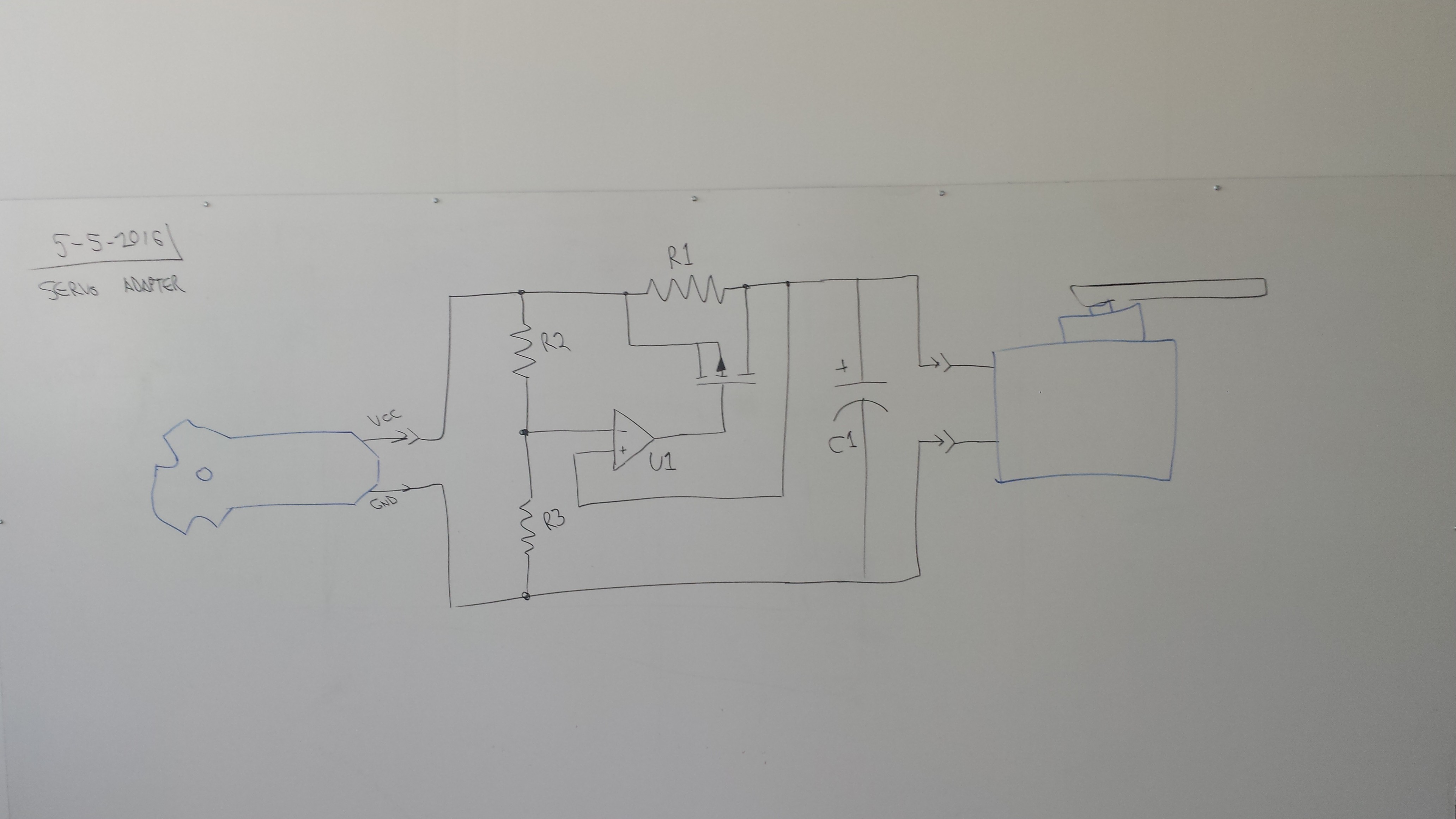
Here's what I came up with:
![]()
The comparator, U1, compares the voltage downstream of R1 to a midpoint set by R2 and R3. It switches on when the voltage drop across the resistor decreases sufficiently, indicating that the capacitor is almost fully charged and the current flowing into it has been reduced to the point that it will not produce an inordinate sag on the power rail. When the comparator does switch on, it charges the gate of the P-channel MOSFET Q1 (I forgot to label this one) which then provides a low-resistance bypass around R1 so the servo is no longer significantly current-limited. The circuit should stay latched once the capacitor is charged, since the MOSFET will expose the positive comparator input to full rail voltage; even if it sags a bit when the servo actuates, the negative input should sag more due to the R2/R3 voltage divider.
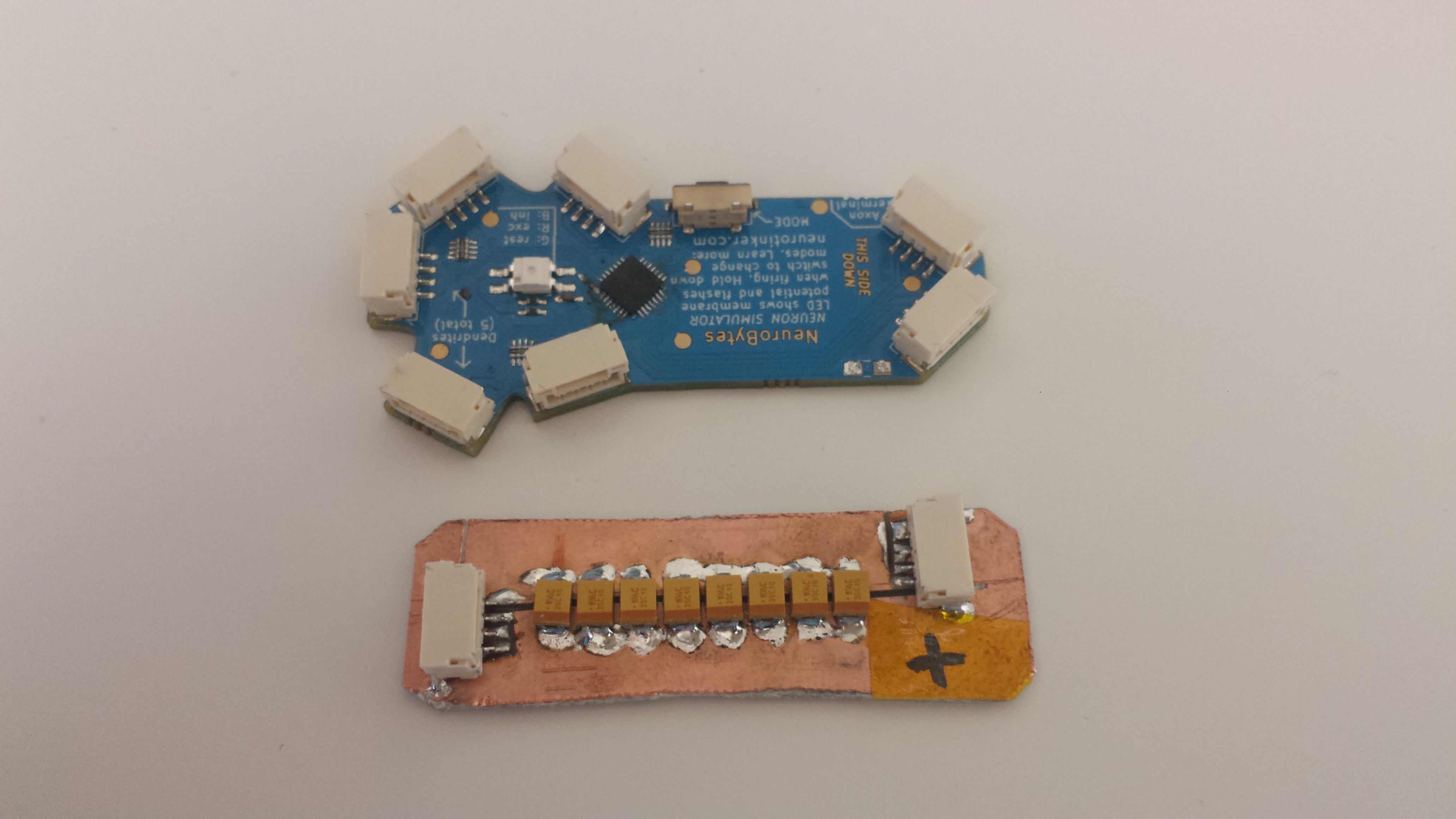
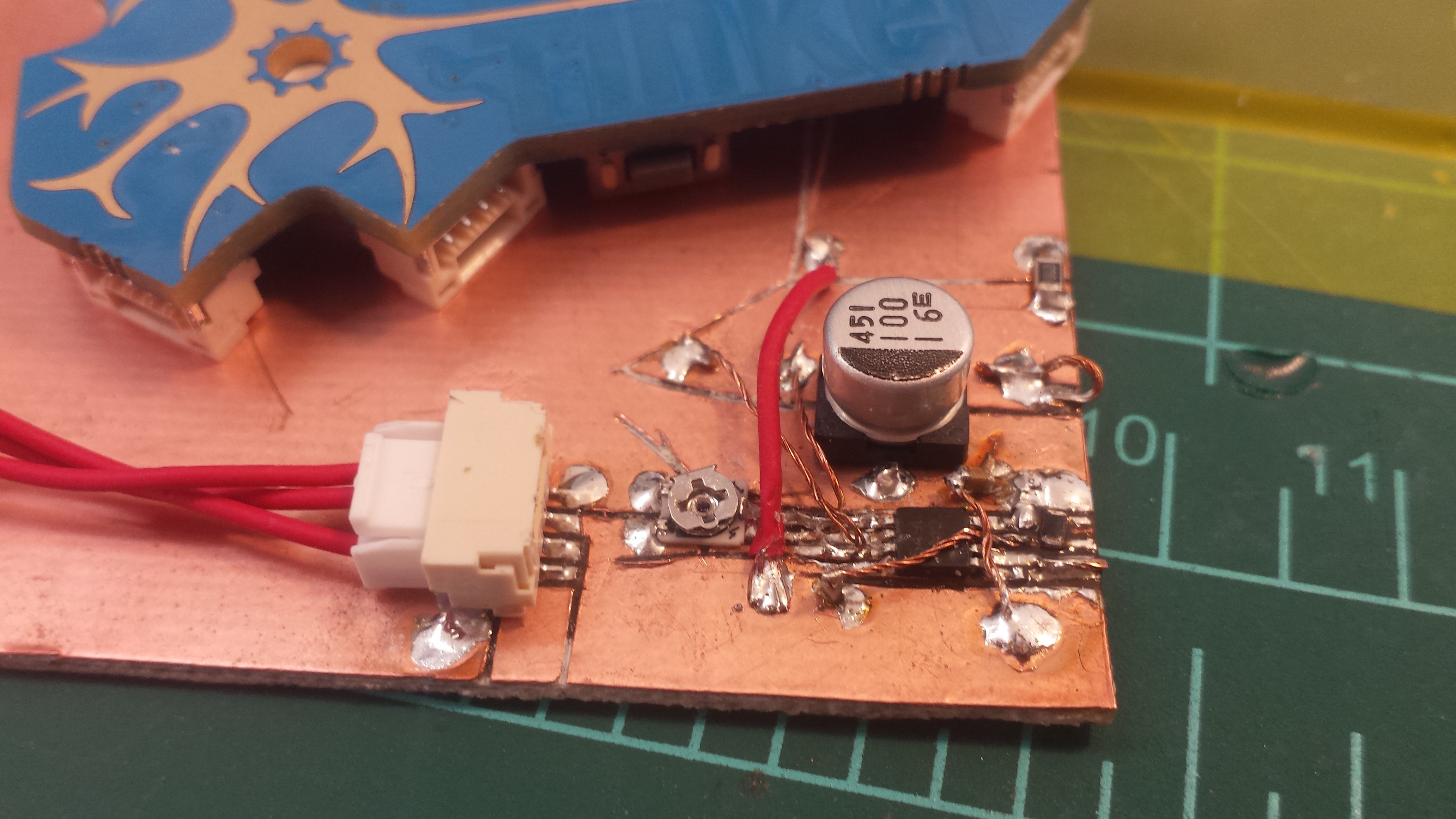
I didn't have a P-channel MOSFET lying around or a dedicated comparator for that matter, but I did have a strip of somewhat overkill op-amps that would work for a quick prototype of the sensing portion of the circuit:
![]()
[note the 10k variable resistor--I wanted to putz with different voltage divider settings--along with the non-tantalum reservoir cap, since it's what I had around. Also, my tombstoned 0.1 uF filter cap fell over but still worked well enough... and yes, I ran out of IPA so this is not de-fluxed!]
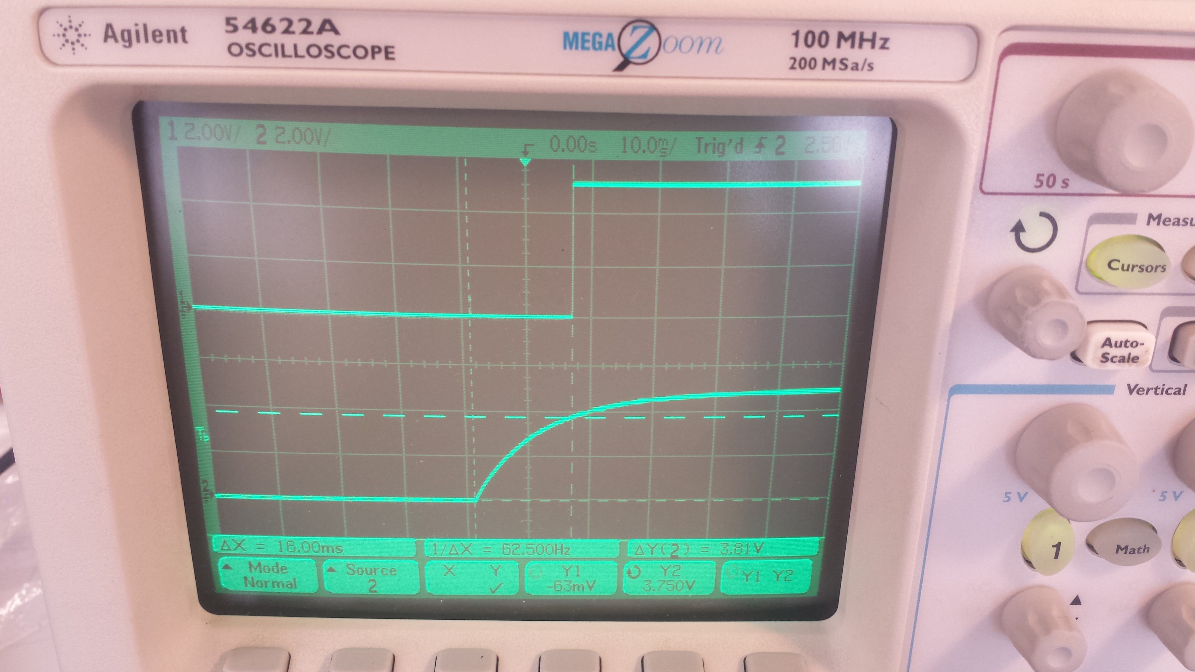
I 'scoped the capacitor charging voltage and the comparator output; the circuit seems to work, as tweaking the variable resistor caused the output to move relative to the capacitor charge initiation:
![]()
[here, the comparator flips on 16 ms after the capacitor starts charging, when the voltage downstream of the current limiting resistor hits 3.75 volts. The resistor value is 1k, since it's what I had lying around...]
I ended the day yesterday by ordering a handful of cheap-o comparators and P-channel MOSFETs that seem to fit the bill (reasonably high current handling capacity, etc). I'll toss up another log once I've tested the full circuit.
SO. Comments? Suggestions? This is the first analog circuit I've ever really designed (/bodged together), so I'd love to hear your thoughts! Am I making this whole thing waaaaaaaaay to complicated?
-
Production, Maker Faire, and Classroom Trials
04/06/2016 at 19:19 • 0 commentsNeuroBytes v0.8 production chugs along. In addition to the actual boards, I've been making a bunch of accessories: cables, switches (we call them 'mechanoreceptors' now!), battery packs, and servo adapters. I've got around 50 boards left out of the original 210. Now, pictures!
![]()
Since my stencil only covers a single board, I've been depanelizing and sanding them first and then applying solder paste. I'm using a kapton stencil from OSH Stencils; I've found a quick wipe on the back every six boards keeps the lines crisp, and thoroughly cleaning it with IPA before storage keeps solder paste from getting crusty.
![]()
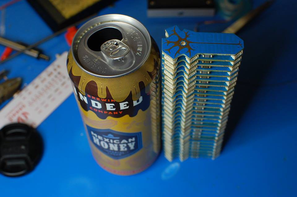
It's important to reward oneself after a successful production run. If you're near Minneapolis, I recommend Indeed Brewing's Mexican Honey. It's a bit on the strong side, but makes for an excellent post-soldering break.
![]()
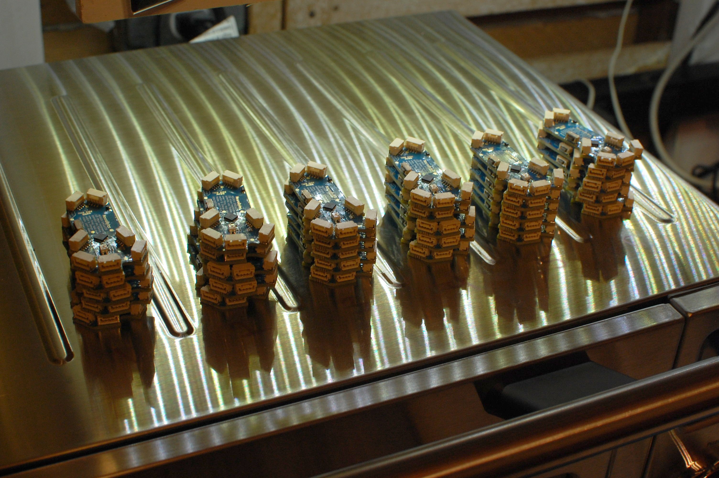
My original reflow oven, as awesome as it looked, had some hot spot issues that discolored boards and limited how many I could do at once. I bit the bullet and upgraded to a sweet convection oven (seen under the thirty new boards in this image). I also skipped the temperature controller altogether; I just set it for 205 C and hit preheat, and all boards (usually 10-20 at a time) reflow within ten seconds of each other around the four minute mark.
![]()
Some time ago I was given the chronograph out of a MIG 23. It's been quite handy for keeping track of rate data, something I never did with the v0.4 run. I'll go into exhaustive detail at some point, but for now just know that for the whole process--paste, place, reflow--I'm at roughly 10 boards per hour. The DIY vacuum tweezers (shown to the right of the standard tweezers) help a bit, but part placement is still a huge time suck.
![]()
Cutting and stripping wires is fun. Ish. Fun-ish. I'll do a separate post on this at some point, as I've got a pretty decent system that works for short-run production. Also, I've been saving the tiny insulation cylinders because they are satisfying to look at when put in a tiny vial.
![]()
A bunch of wires. I also made stubby wires. Red ones are excitatory, while blue wires (not shown) are inhibitory. Mark + cut + strip + crimp + assemble = 19 cables/hr, give or take. Not bad.
![]()
Emergency power supplies! These dumb little boards are just LDOs with the associated filter capacitors, and are sized to fit into the battery packs I found at the local surplus store. I'll do a separate post about this process at some point. Emergency, because I forgot I needed to make power supplies until a day before the UPS drop-dead date for our upcoming trials.
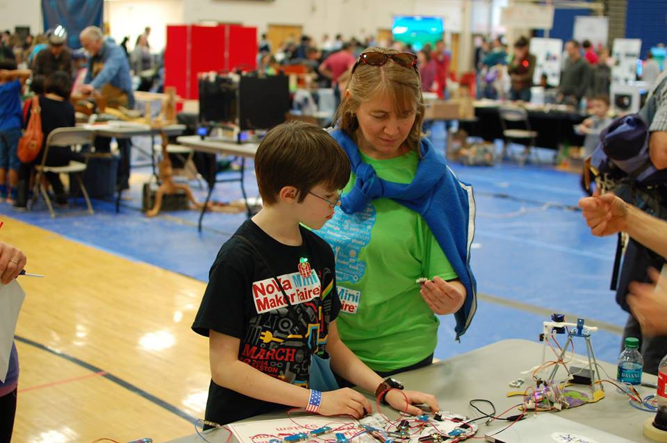
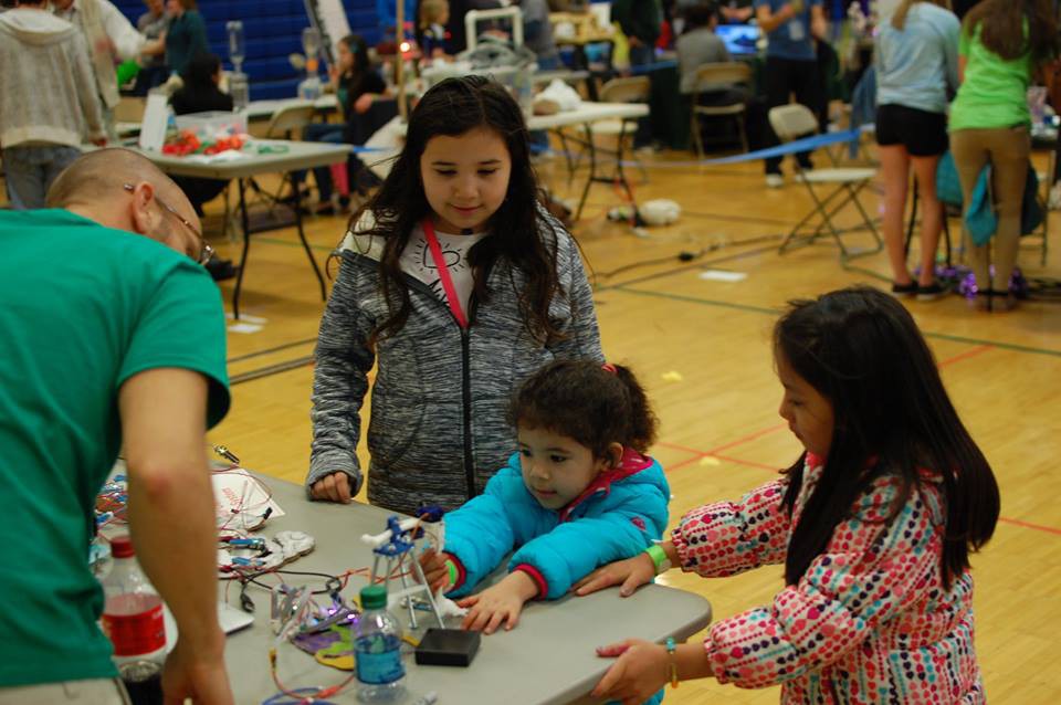
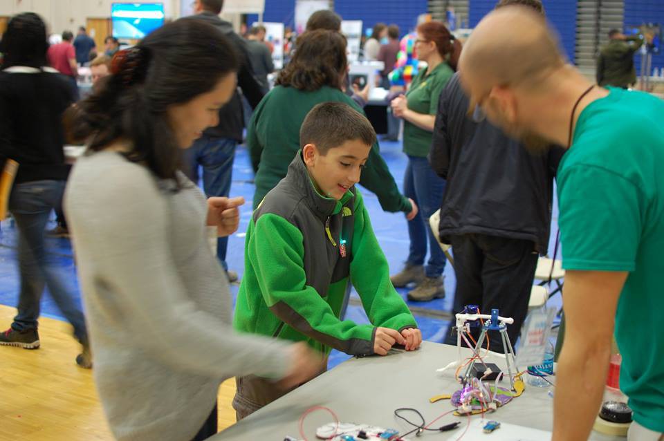
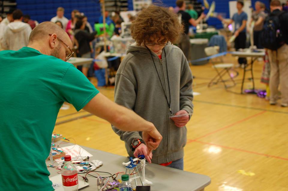
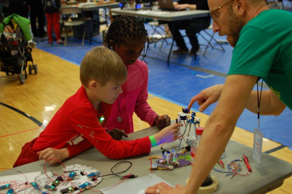
A few weeks ago, Joe and I headed out to DC for an NSF SBIR conference. The trip happened to coincide with the NoVA Maker Faire in Reston, VA, so we got a table and taught a ton of youngsters about action potentials and the patellar reflex:
![]()
![]()
![]()
![]()
![]()
As with the San Diego event last fall, NoVA Maker Faire was an amazing event. We learned a lot about how students interact with our platform and got some great durability testing in. Also, a ton of parents that wanted to know how to buy NeuroBytes, so I suppose that is nice as well. Soon, parents!
The rubber hits the road this week and next. Earlier this month, we shipped ten patellar kits to Anj Petto at the University of Wisconsin in Milwaukee:
![]()
They're going to use the platform to teach the reflex arc in an introductory anatomy and physiology class; something like 200 students across ten recitations will be using the product, and we'll be collecting tons of data related to educational efficacy and more. We're also going to teach the same unit at Patrick Henry High School in Minneapolis--three class periods over three days in late April, each with roughly 20 students. This will give us a lot of good information as we lock down the design for truly scaled production.
Finally, an acknowledgement--I've slacked a bit on our commitment to be an Open Source Hardware Company. We don't have anything for sale (yet), and we've just been too busy iterating and modifying the design to get BOMs, schematics, board layouts, and code posted. No guarantees in the short run--the v0.8 design is still very much a prototype--but I do intend to formally release everything in the coming months. I'd rather do this after the design is finalized to avoid needless revisions, but I am happy to do so sooner if anyone is interested.
-
New boards work!
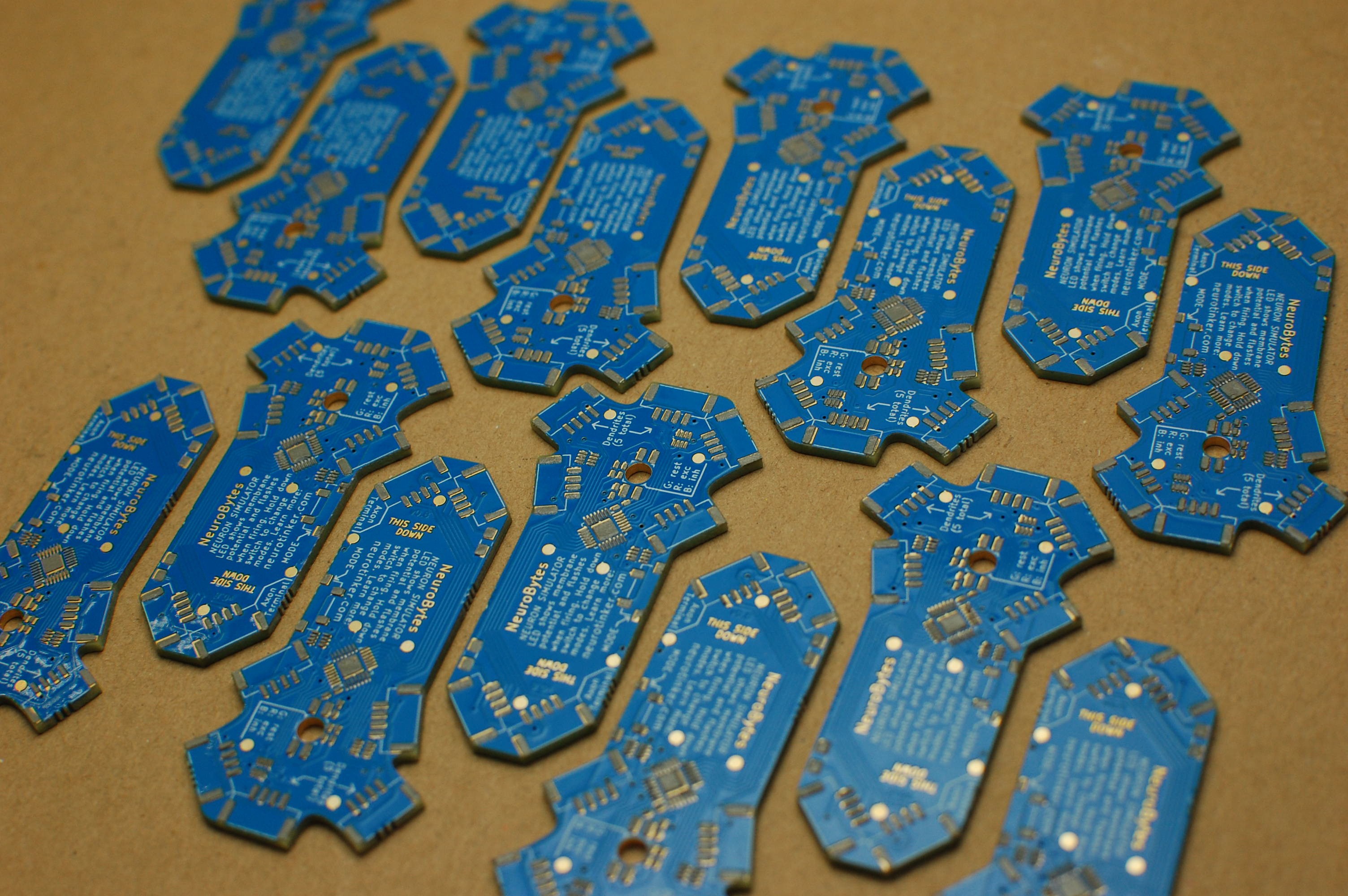
03/08/2016 at 15:01 • 6 commentsPanels arrived from Gold Phoenix. Everything looks excellent--silkscreen is readable, solder mask seems accurate, etc.
![]()
![]()
I depanelized, pasted, placed, and reflowed a panel of NeuroBytes v0.8 yesterday; everything seems to work! I made the pads a bit elongated so the boards can be hand-reworked; since I based my stencil on this pattern too, I occasionally get solder bridges on the QFN ATtiny and the resistor networks. Easy enough to fix with an iron.
![]()
The bottom mounted RGB LEDs look GREAT. Plating the through-hole (and making it a wee bit larger than the LED datasheet spec) was a great choice.
-
Scaling, coding, etc..
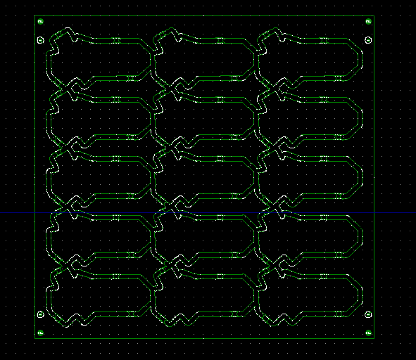
03/04/2016 at 21:59 • 0 commentsProgress! I ordered the stuff for a 210-piece NeuroBytes v0.8 run. They'll be light blue with white silkscreen, just like the v0.4 boards from 2014; however, they'll ditch the bumpy silver HASL coating for sleek ENIG gold. Minimal changes from the six prototype boards beyond the color; I futzed about with the silkscreen a bit and pulled a lone 10k resistor into one of the 4x networks.
![]()
[Above: I had the PCB vendor take care of panelizing the v08 outline; it's routed with four mousebites per board. Not a completely optimal use of space, but having them take care of it saved me a good bit of time. Boards are scheduled to arrive in Minneapolis next Tuesday, 3/8/2016.]
The Digi-Key box showed up yesterday. While the 210-piece run will nominally require 1470 JST GH headers, quantity discounts meant it made sense for me to get my hands on my first full reel:
[also shown: 1000' spool of 26 AWG wire.]![]()
I'm planning to build up a bunch of cables between now and Tuesday, and then get a few dozen boards churned out midweek. And yes, I did get a stencil this time (from OSH Stencils)--it's Kapton (captain?) so I'm guessing it won't last the whole run, but it'll do for now:
![]() [in-focus stencil with blurry PCB rear layer in the background...]
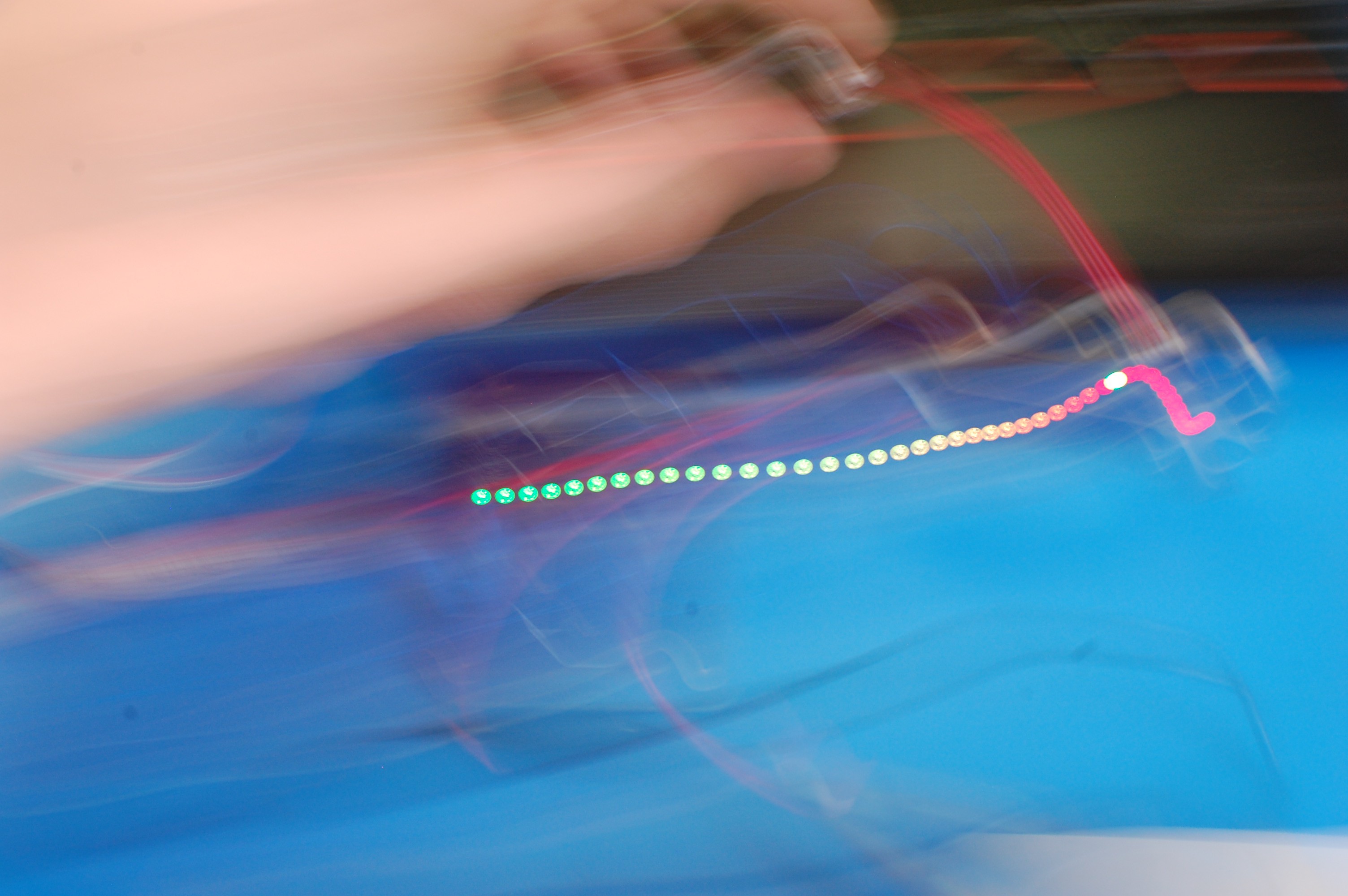
[in-focus stencil with blurry PCB rear layer in the background...]I've also been making progress on firmware. The Izhikevich model works well but isn't ideal for demonstrating simple integrate-and-fire behavior between a few NeuroBytes, so I've been porting a copy of the v0.4 firmware over to the ATtiny88 platform. I've started using the 'swing the camera' debug method to track down pesky PWM glitches:
![]() [the glitch is the single green flash between red flashes..]
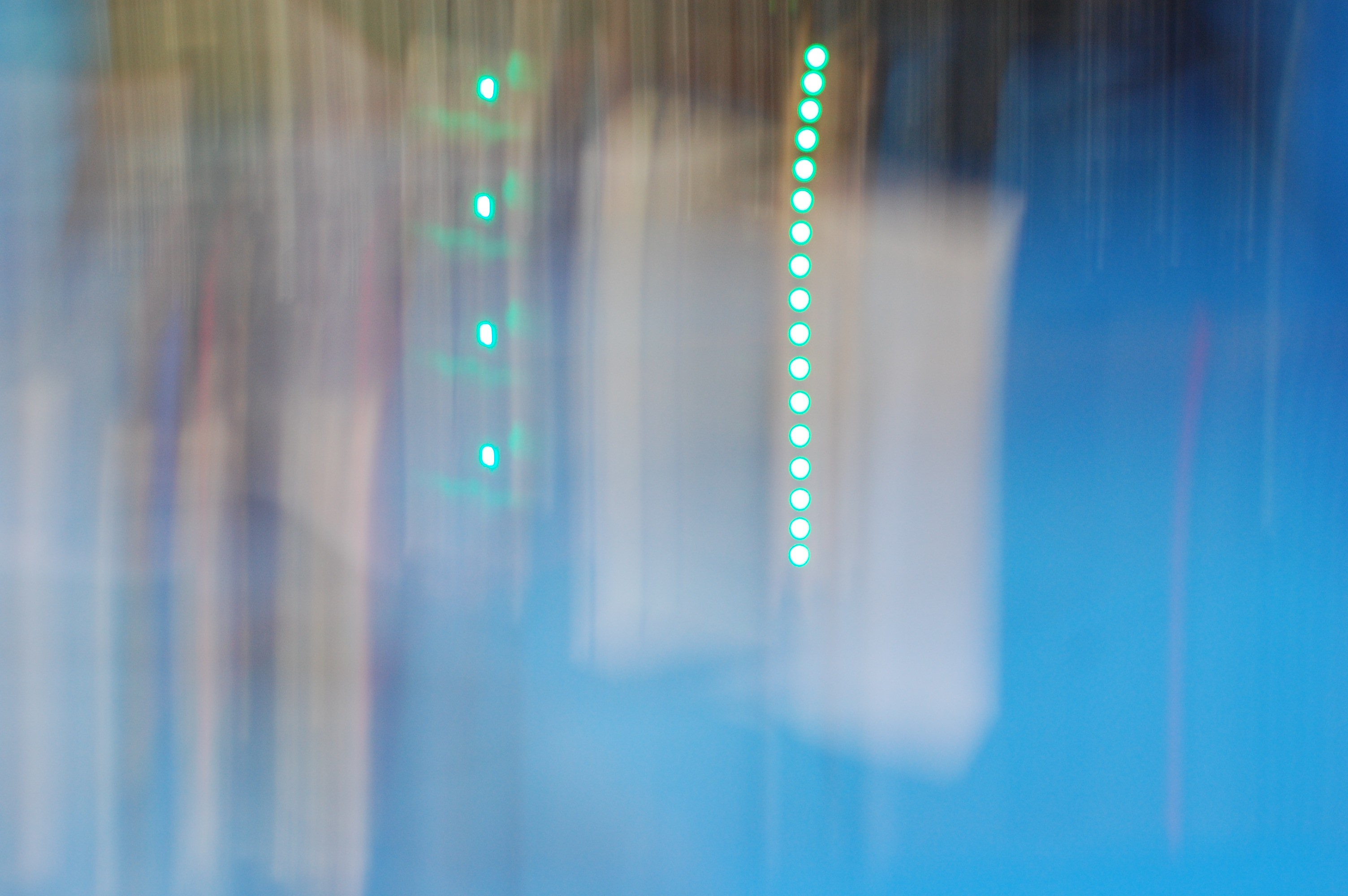
[the glitch is the single green flash between red flashes..]Also, this photography method provides a great visual for bragging a bit about the firmware efficiency improvements I've implemented. I mean, let's be honest--the v0.4 firmware was _terrible_, and the new code could probably still be improved a lot, but the >4x refresh rate improvement is great:
![]() [taken at 1/13 s shutter speed]
[taken at 1/13 s shutter speed]So yeah. Work is cut out for the next week. Finish firmware, build cables, assemble boards, update GitHub repo. With any luck, we'll have a box out to our collaborators by mid- to late-week, and will have enough devices left over to show off at Maker Faire NoVa next weekend.
-
Latest prototype [v0.8] details!
02/23/2016 at 16:48 • 1 commentWe've been rockin' a 4-week hardware+firmware iteration cycle which has been hectic to say the least. Talking to a lot of potential customers and end users, quickly integrating their suggestions into new models, trying new components, etc... it's been fun. Unfortunate side effect: my documentation efforts are woefully out of date.
NeuroBytes v0.6 and v0.7 have come and gone. If you want to learn more about either generation, head over to the section of our website that details prototype iterations and click through to the associated entries at the bottom. I'm going to skip recreating that information here as it's redundant at this point and I'd rather talk about the latest version!
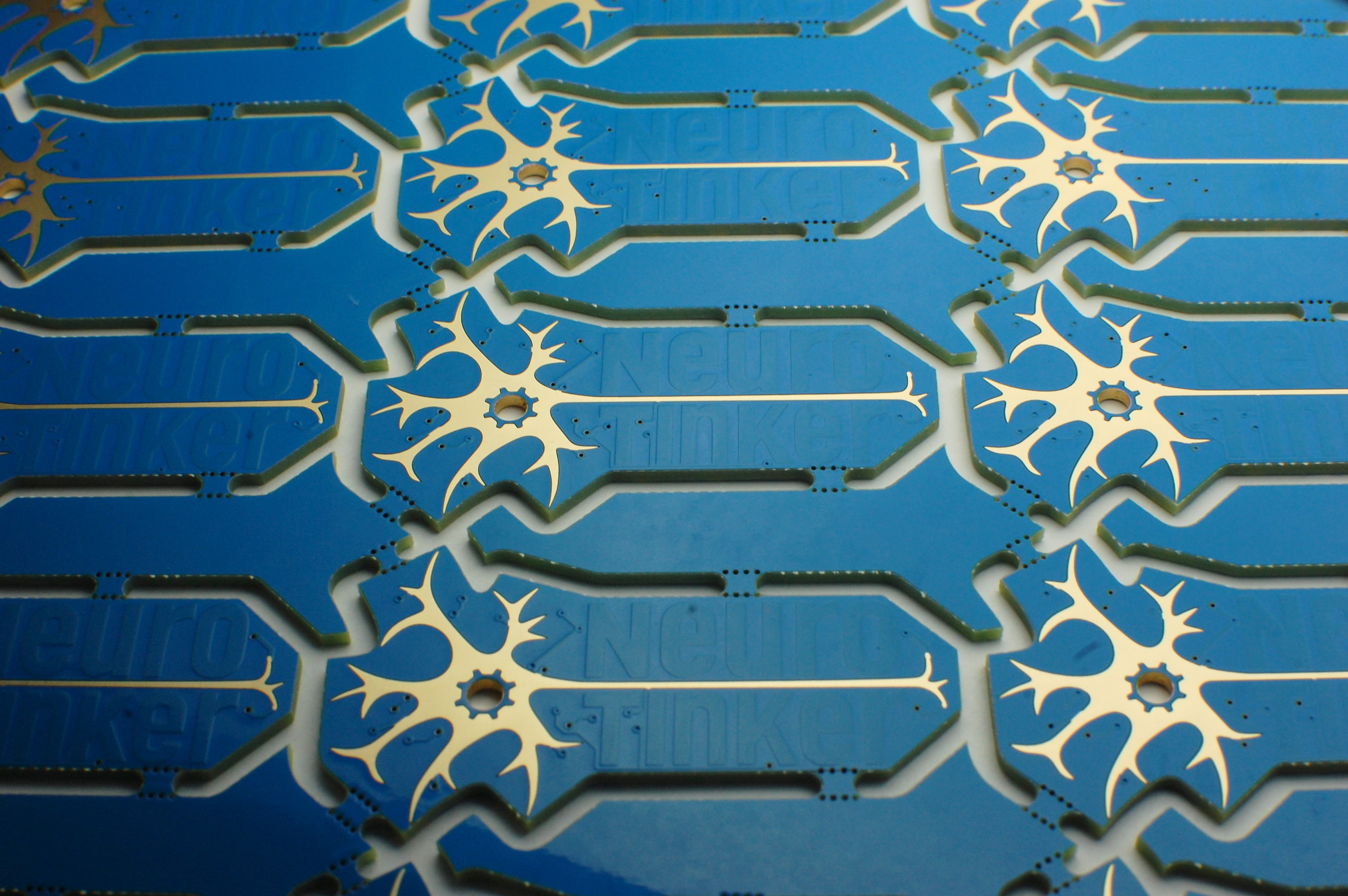
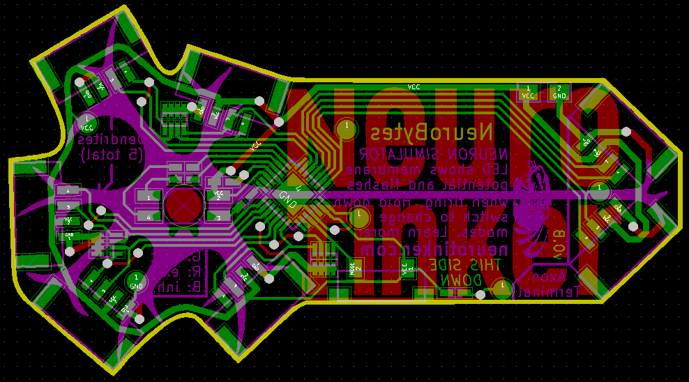
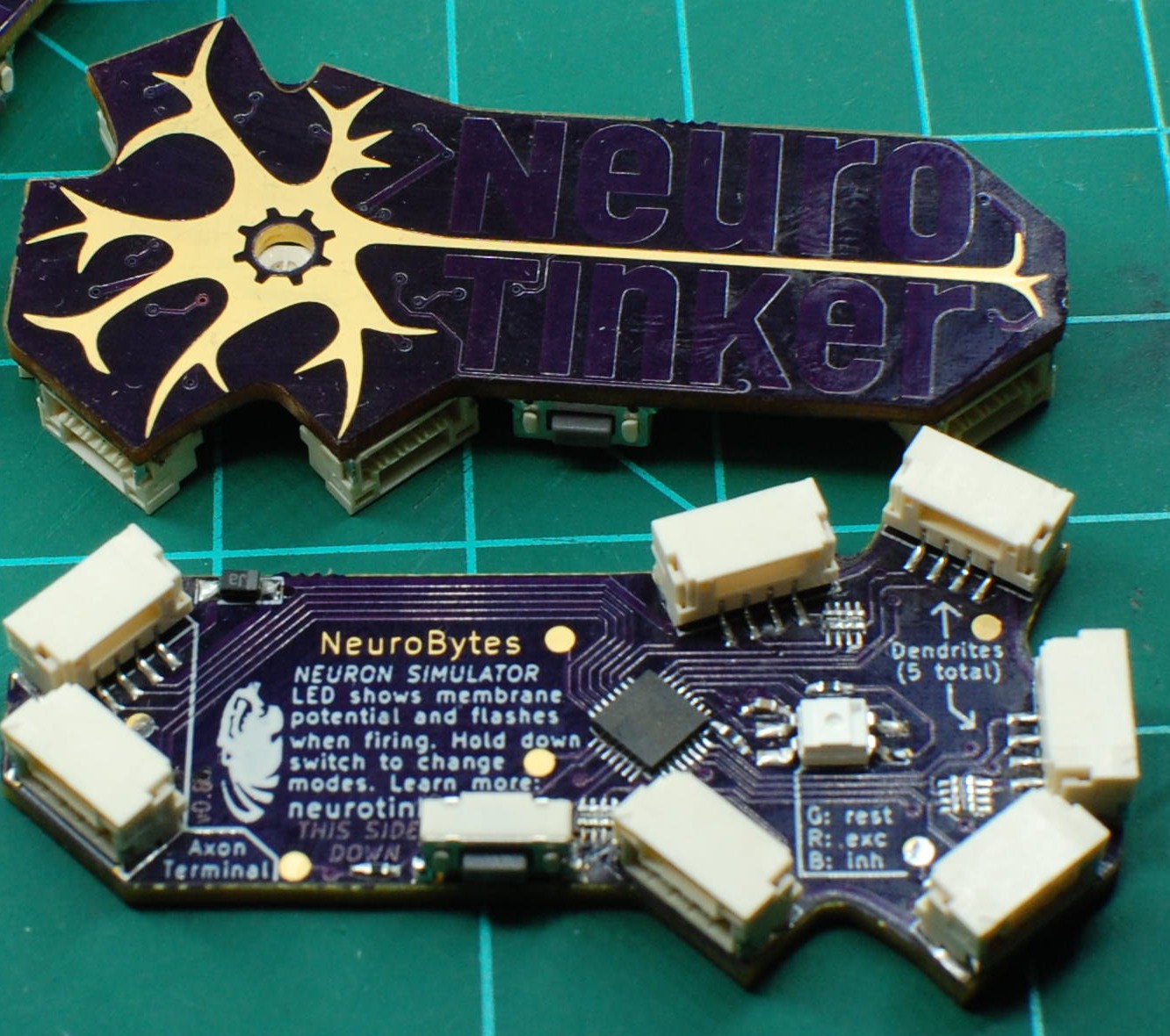
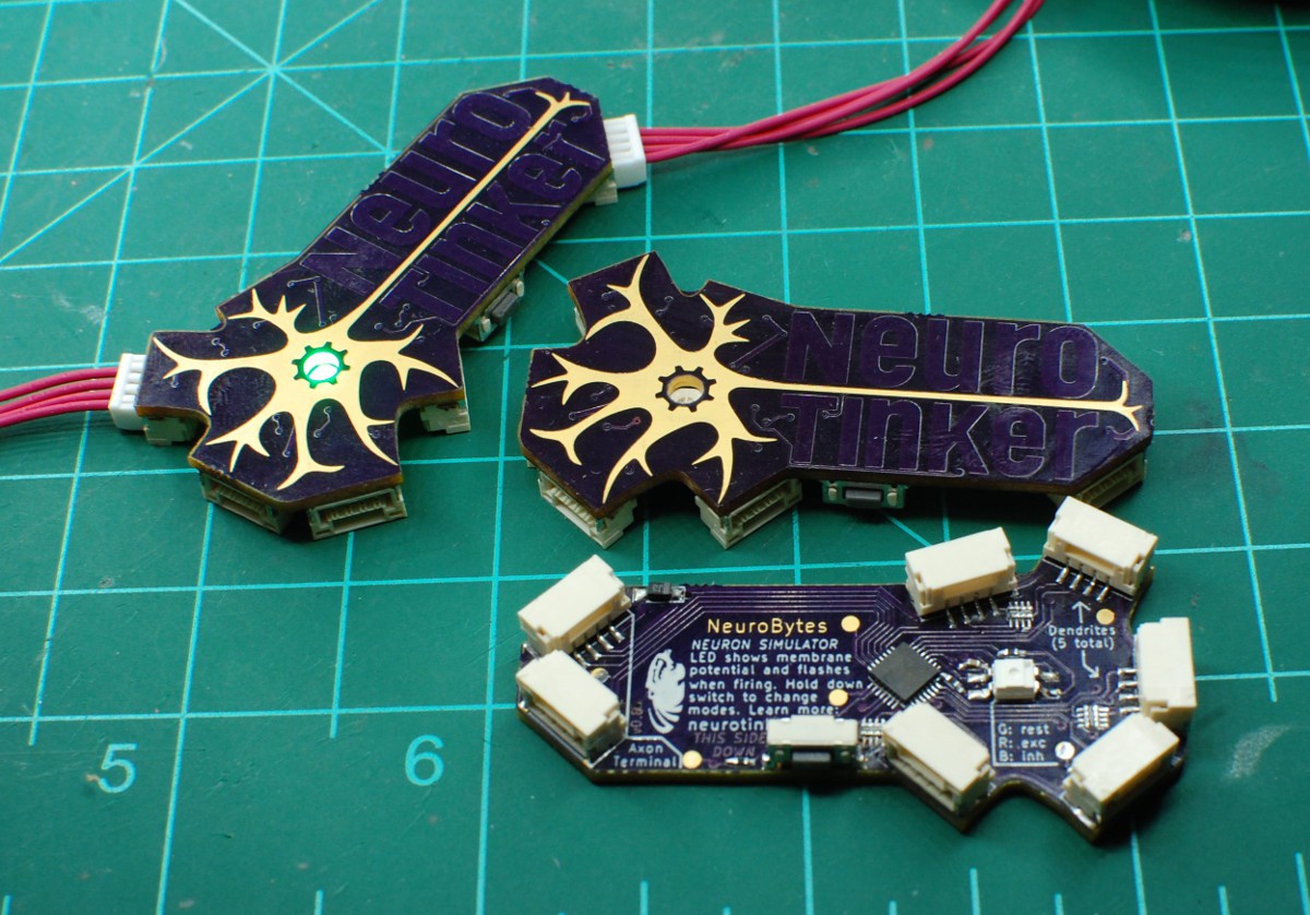
![]()
[v0.8 final board design, 30mm x 55mm including protrusions.]
Notes:
- Similar electrical specs to v0.7: ATtiny88 in a VQFN28 package, five dendrites (inputs), two axons (outputs), single RGB LED. Adds back in the mode switch from v0.6. Pogo pads for programming with an associated (and yet-to-be-constructed) jig.
- Board outline is based on our logo, with the five dendrites extending out from the cell nucleus at "organic" lengths and angles. Top of the board is super clean--all the user sees is the neuron shape rendered in ENIG, while the NEURO TINKER name is soldermask-covered copper.
- The center of the gear on the logo is a 3mm hole, straddled on the back of the board by a bottom-mount RGB LED.
- Connectors are surface mount, right-angle, 1.25mm spacing JST GH. They have locking tabs that are easy to spot, and pop in and out easily once the lever is pushed. More details on how I build the cables in another post, once I have more raw materials in hand (tomorrow).
- No more massive hole on the back of the board for easier VQFN ground pad soldering; for these prototypes, I reflowed these chips in my toaster oven, touched up the edges with my trusty WES-51, and hand-soldered the rest of the parts. Worked well enough, although I'm still having trouble getting one of the boards to listen to commands. So call it 5/6 yield.
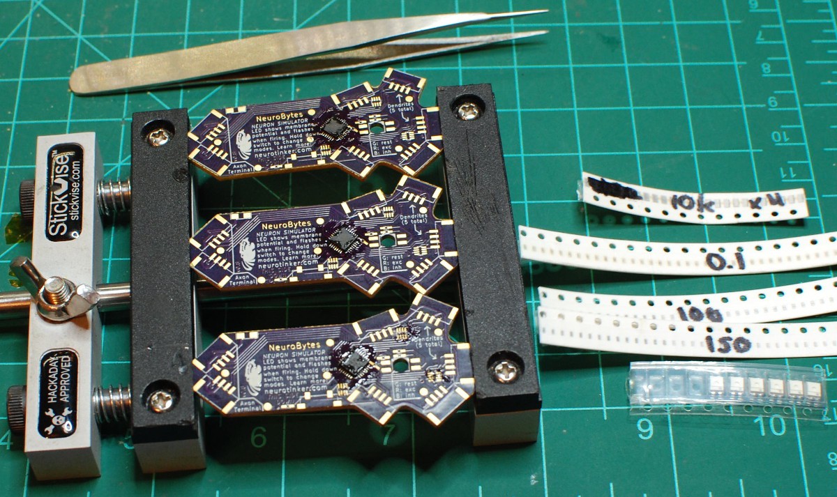
![]()
[#Stickvise with the crucial logo placement... well played, guys.]
We wanted this version to look more like a neuron; our logo was a good starting point, so we ended up using it as the basis for the board design. It means we can't v-score the boards to panelize them, but everyone we've spoken to agrees that the product needs to look like its biological analog. We're also serious about avoiding an enclosure--that adds cost and waste and reduces our flexibility in terms of future iterations (tooling is expensive!); hence, bottom-mounting all of the parts so the product is uncluttered while in use.
![]()
[please ignore the wonky filter cap between the LED and the IC...]
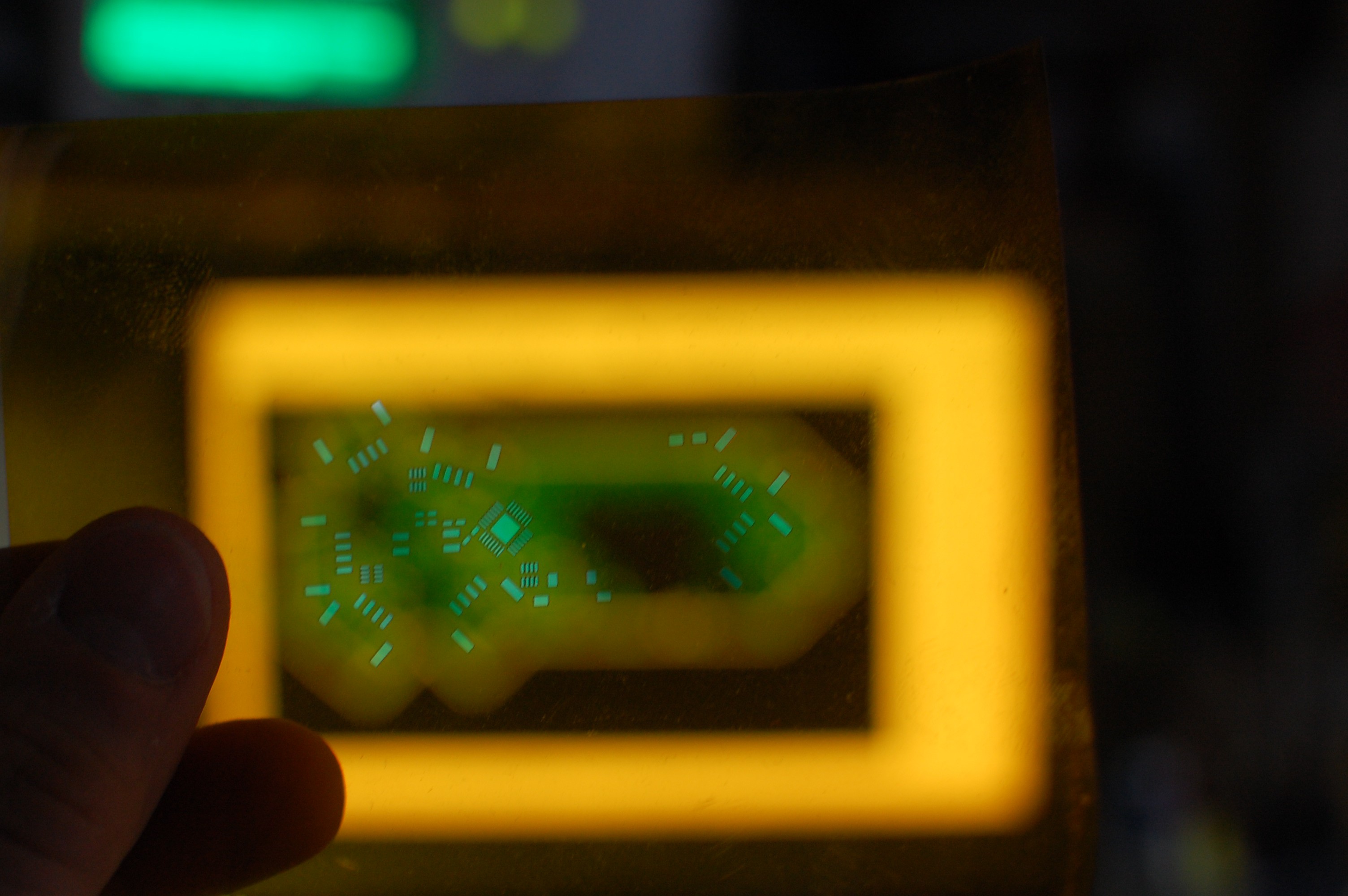
As you may have noticed in previous project logs (or on our website), we're working with Anj Petto at UW-M to trial the product in a freshman-level A&P course in April. So... at least for this round of prototypes, we also included a mascot to the left of the printed instructions. Helped us push the limits of OSHpark's silkscreen, and it ended up turning out quite well!
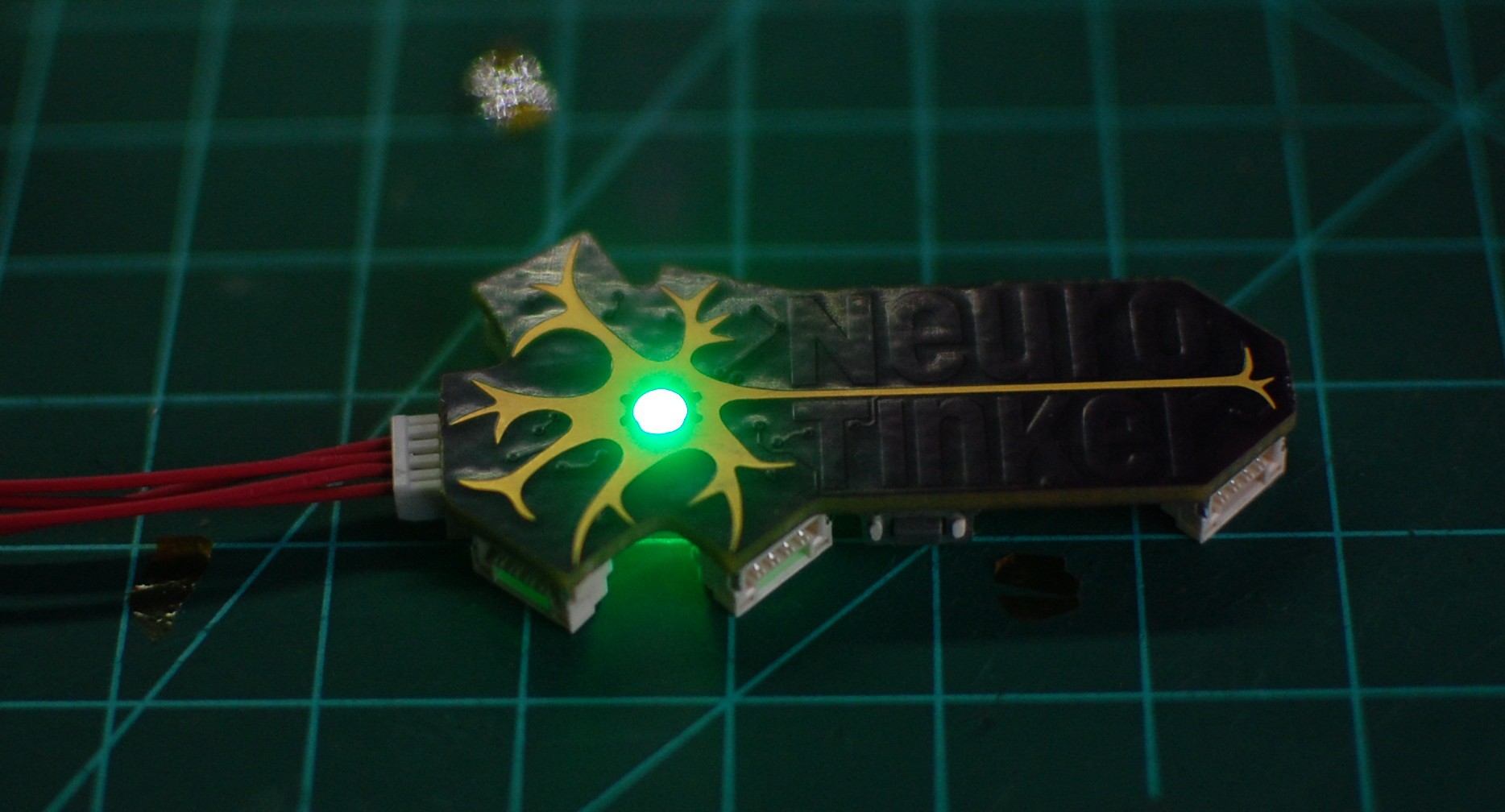
![]()
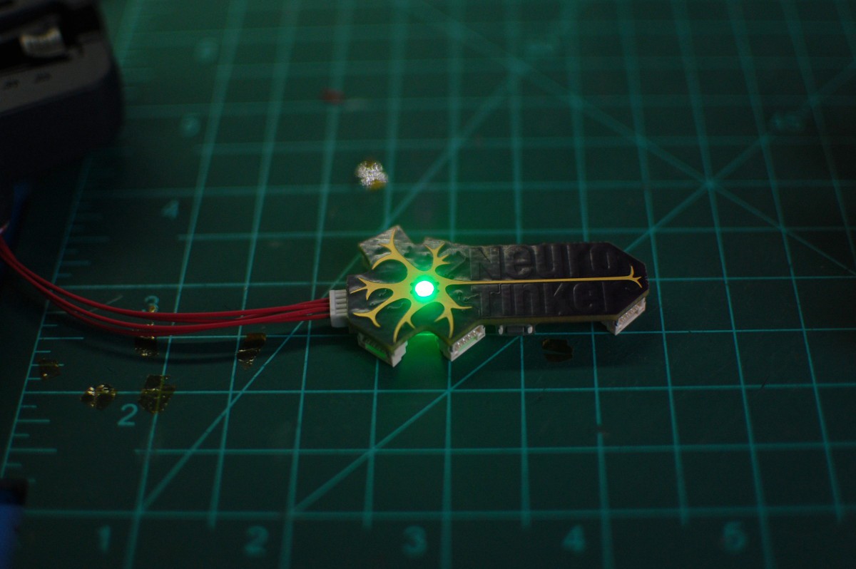
[full brightness green-channel test looks amazing!]
Up next: finishing the pogo rig for speedy programming, tweaking the design a tiny bit (specifically, adjusting routing radii to avoid undershoot), porting over the v0.7 firmware with a few bug fixes, updating the GitHub repo (finally.. ), and ordering a larger run of boards--this time I'll get a stencil, too. Stay tuned!
-
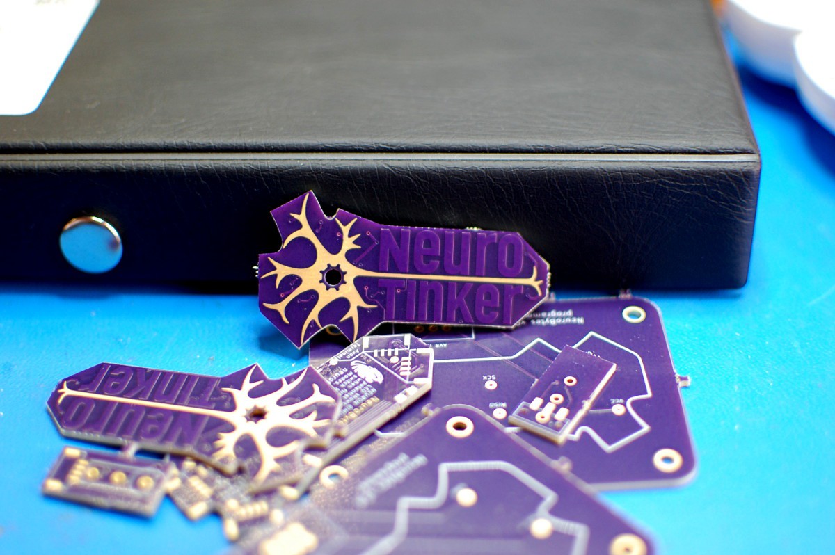
v0.8 first light!
02/23/2016 at 03:47 • 0 commentsMore details soon. For now, pictures!
![]()
![]()
![]()