Close
0%
0%

ESP8266 Development PCB's

Development board for ESP8266 the make up of which can be decided by the community

Similar projects worth following
I recently designed a small 30x50mm PCB for testing one of my projects but when I looked at the cost form most of the small quantity suppliers for ten units, it was a little out of my budget.

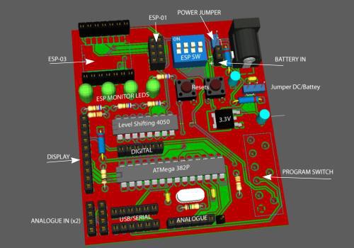
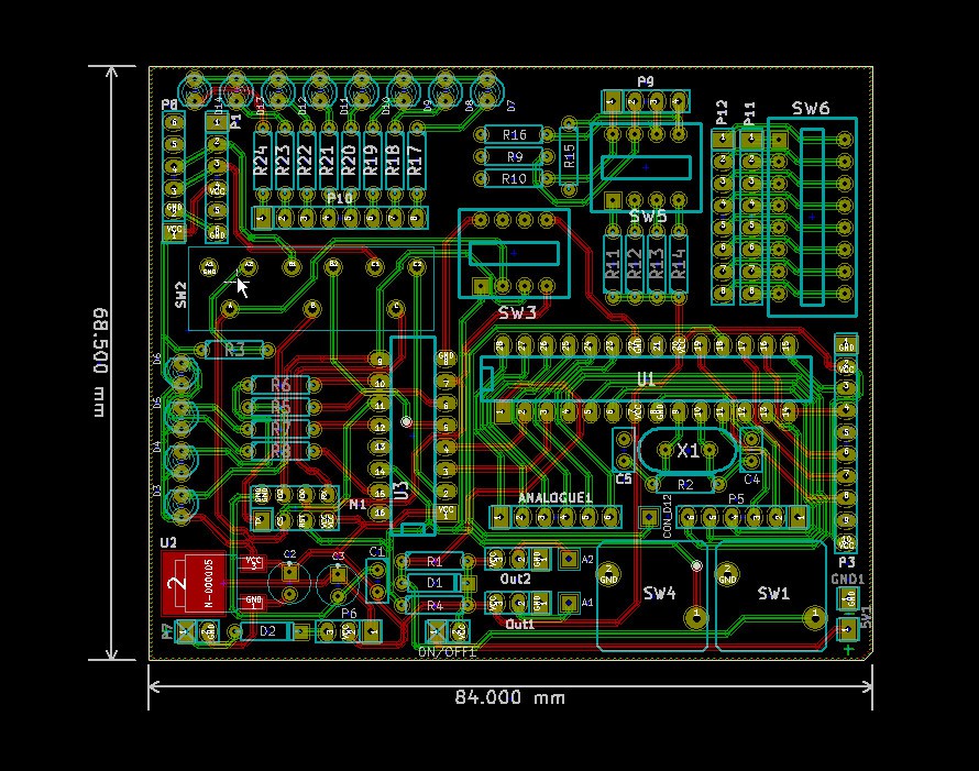
My current design is not ideal for development but it does allow me to move my Arduino developed sketch to the on-board ATMega 328. The board includes a header for the ESP8266 module and a ten pin header to connection an inexpensive 1.8" TFT display used by the sketch and also serves as a debug console so no computer is required for testing...

This particular design with minor alterations might prove useful to quite a few people but is not the subject of this project, it only serves as an example...

In order to determine exactly what an ESP8266 development board should include, I am hoping for input from the community... If there's enough consensus it might be possible to design a board that suits enough people to allow sharing manufacturing cost making it more affordable...

The development board supports

  • Programming and testing the ESP8266...
  • Ability to move Arduino sketch to on-board ATMega for testing...
  • Six digital and six analogie pins available (ATMega)...
  • Two three pin headers for connection of analogue devices (pots, sensor etc)...
  • Eight general purpose active low Leds for monitoring IO pins (ESP or ATMega)...
  • Header for 1.8" TFT used for projects and to replaces the console for debug...
  • Buffered (level-shifting) for TX/RX between devices...
  • Monitoring of four pins of the ESP8266 (buffered and connected to Leds)...
  • Reset buttons for both ATMega and ESP8266...
  • On-board 3.3 volt, 1.5 Amp regulator...
  • Header for connecting external battery (in-line diode for protection)...

The next will add breakout for ESP8266 version 3 (all IO pins)
Details may change from time to time...

  • 1 × ESP8266 WiFi Module
  • 1 × 4050 CMOS Buffer & Level Shifter
  • 1 × L2303 USB to Serial Module
  • 1 × 1.8" TFT Small TFT Display
  • 1 × LD1117V33 Power Management ICs / Linear Voltage Regulators and LDOs

View all 7 components

  • Test Board for ESP-201

    Michael O'Toole10/11/2015 at 04:10 2 comments

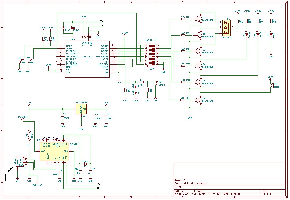
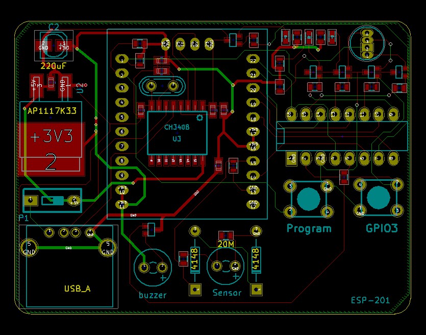
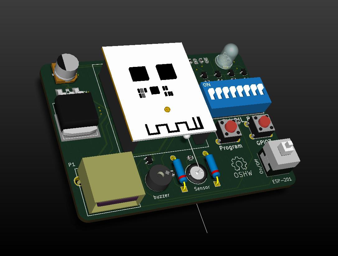
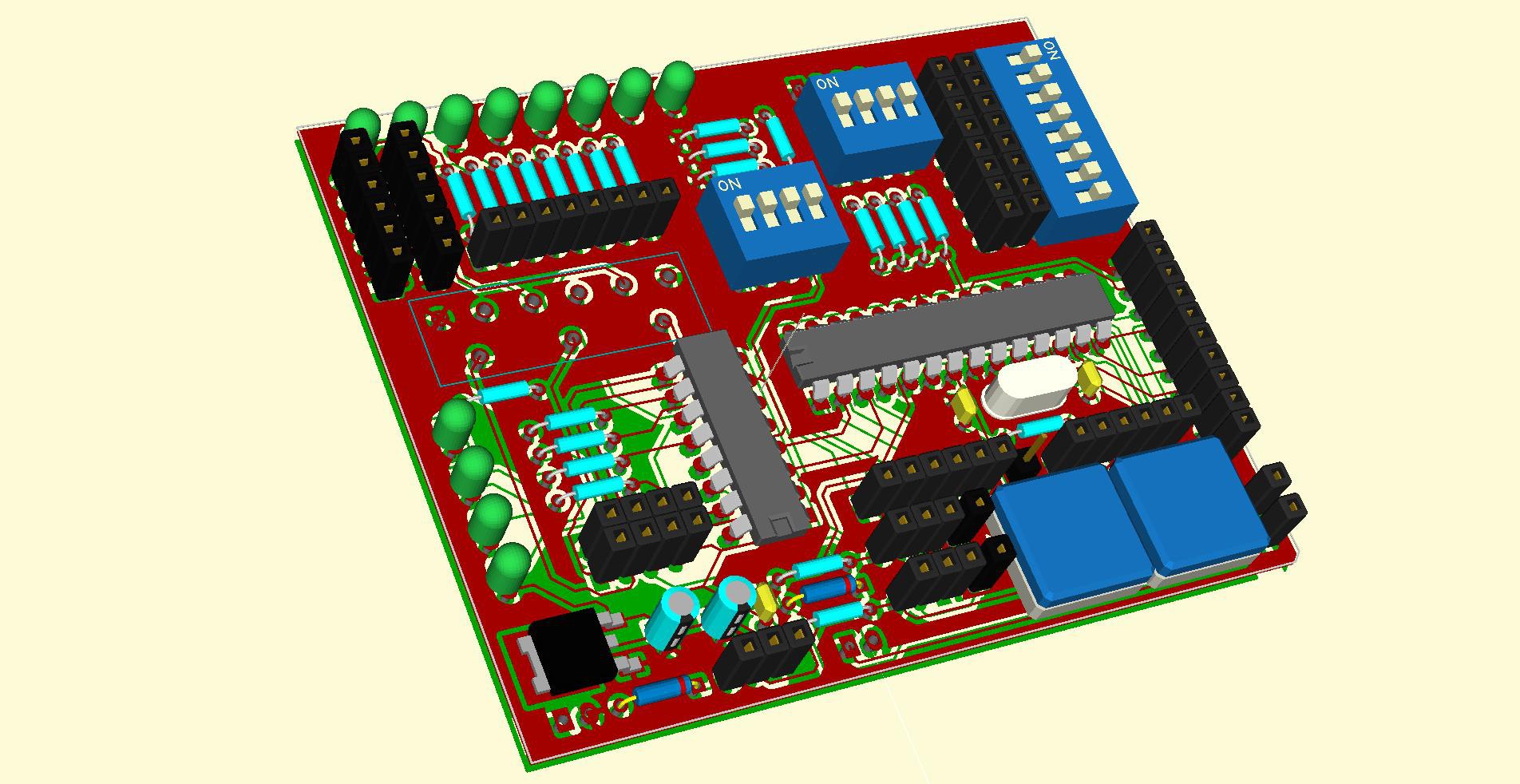
    Just in case anyone wants a test board based on the little white ESP-120 Module, here's some ideas... (KiCad)

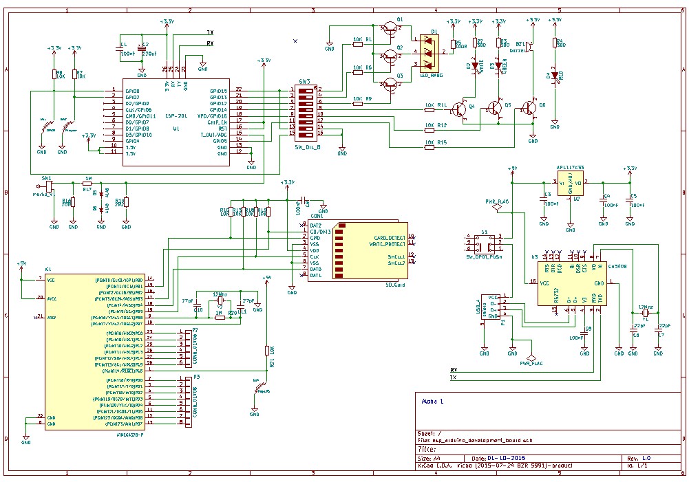
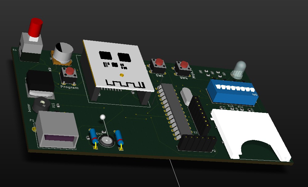
    The board can be used for testing and programming the ESP-201 module... It's pretty much the same as a board I found when googling but aimed at testing inertia sensor using the ADC... All files available on request...

    The unit is powered by USB and contains a Buzzer, RGB Led and a Piezo sensor...

    The USB circuitry (CH340B) is under the ESP201 (little white board module).

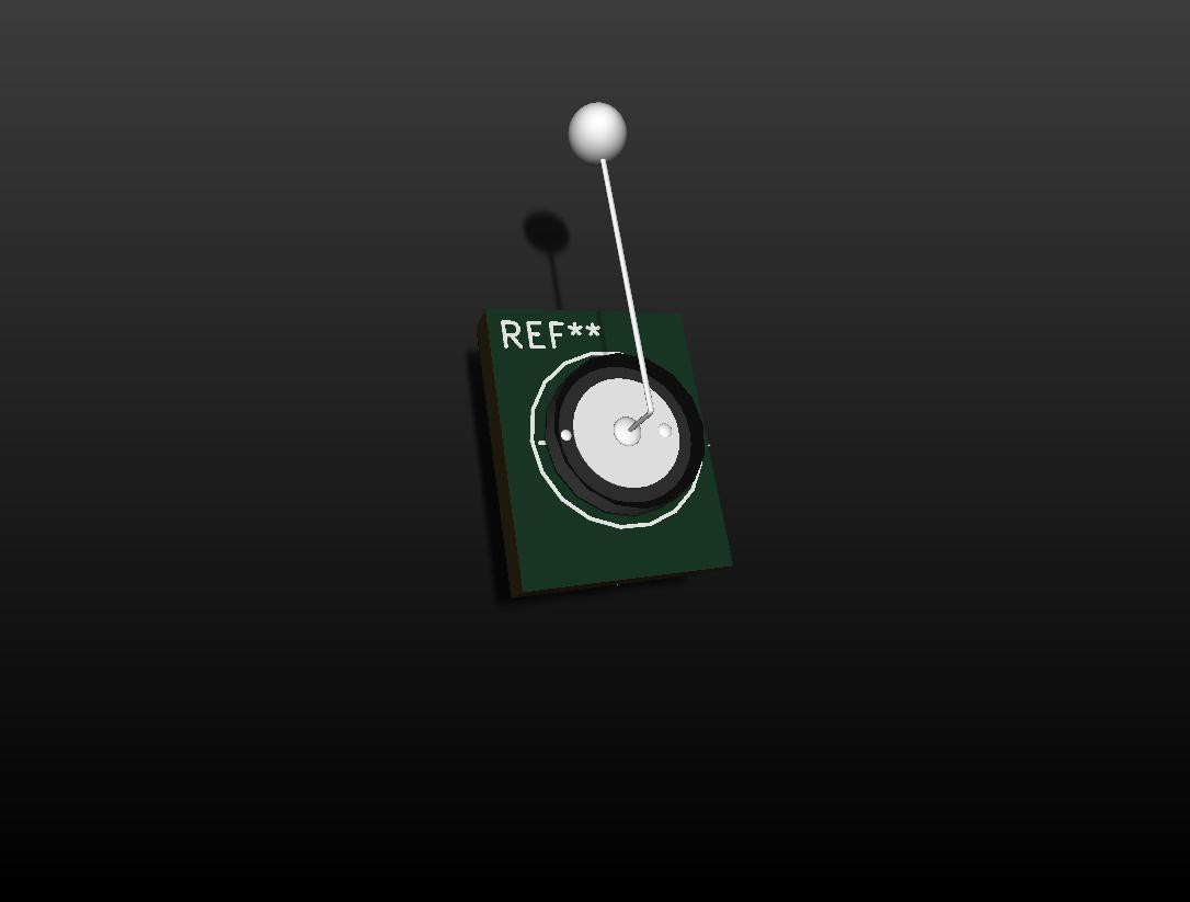
    Note my design for the sensor, it's a standard inexpensive piezo disk modified to greatly enhance it's performance when used as a sensor... the design can out perform sensors costing many tens of dollars...

    I managed to replaced a $34 sensor with a $2 sensor and small weight connected to a piece of wire soldered to the disk... Additionally, if the weight is resting lightly on a surface (such as a window or door frame), vibration is transmitted directly again greatly improving detection...

    Updated version:

    includes on-board SD reader, USB to Serial CH340B, AtMega328, Inertia sensor for AD testing etc... Will probably redo this for through-hole as it's easier to build... I've yet to test it so don't be surprised if I screw up and I have still to add the TFT for debug...

    ...

  • Programming ESP with Arduino IDE

    Michael O'Toole04/28/2015 at 11:51 0 comments

    Looks like you can now program the ESP series of boards directly from the Arduino IDE


    This is a game changer for me (and I guess many others)... no longer do we require an intermediate processor to do our bidding... Most simple control applications can happily be accommodated by the little device on its own...

    Looks like there are a few positives including a faster processor too... more pros and cons later...

    Of course I still need a development board, with options to handle more of the ESP board revisions but basically the circuitry is greatly simplified... I guess it's back to the drawing board...

    New Criteria:

    • Support ESP 01, 07 and 12 (and possibly more)...
    • Display status of all GPIO's (all buffered, 9 pins available)...
    • Display RX/TX status (buffered)...
    • Provide support for working with the ADC (LDR or similar)...
    • Capable of both Testing and Programming...
    • Capable of testing several ESP models (01, 07, 12, ?)...
    • A well regulated 3.3 volts @ 800mA (battery & charge circuit option)...
    • Breadboard connectivity (all pins are broken out)...
    • Self contained? USB? TH/SM or both?...

    ...

    More info here... https://hackaday.io/project/5150-arduino-ide-for-esp8266-quickstart-guide


    Comment:

    It's been noted that I design a lot of development boards but don't appear to build them.

    Rational:

    In the ESP world things change very quickly. This results in me having to modify designs to accommodate these changes, besides, I don't have the cash to prototype everything I design.

    Old guy on fixed income...

  • A little Program Board

    Michael O'Toole03/18/2015 at 16:21 0 comments

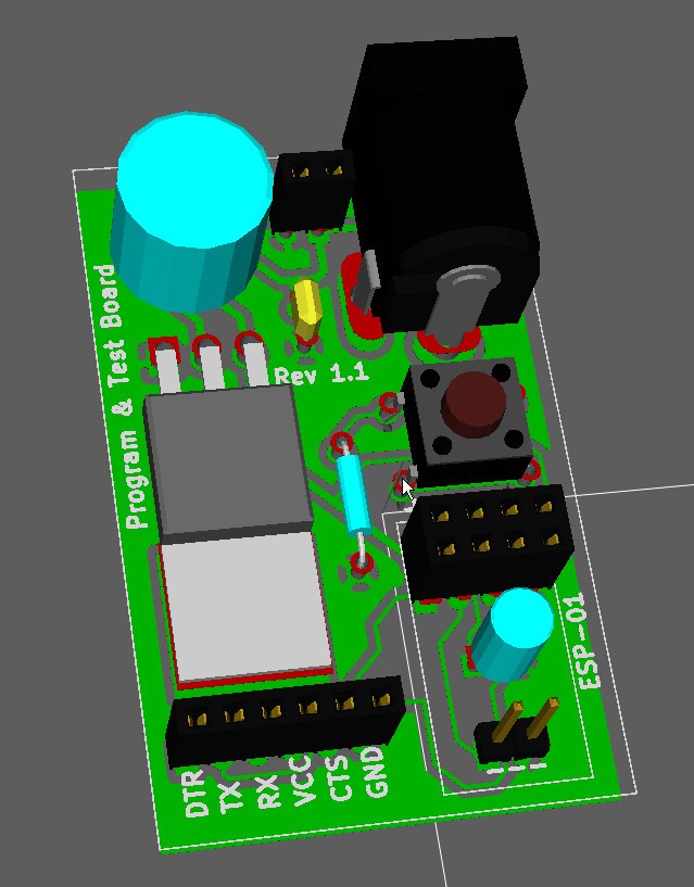
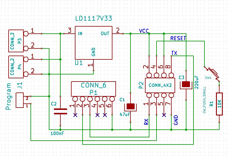
    Just adding a little program board for ESP 01

    All through-hole and single sided so easy to make...

    J1 is a simple jumper to allow programming... remove for testing...

    Also added a reset button and option two pin connector for supply (in place of 5 volt jack)...

  • Version with ESP8266 3

    Michael O'Toole12/18/2014 at 11:46 0 comments

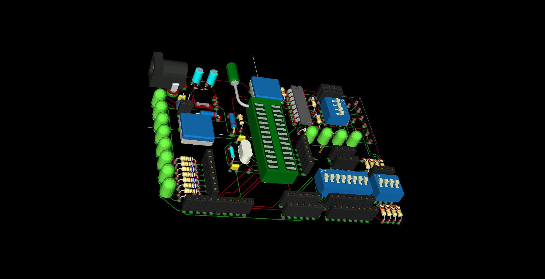
    Now you test ESP-01 and ESP-03

    • You can solder one ESP-03 directly or create a few small breakout boards, add some header pins and plug it in, just like the standard ESP-01 version...
    • Simplified the board by dropped the Leds and buttons, and changed reset switches to something a little more common...
    • The ATMega should be socket mounted... (will add zif socket to final version)...

    Along with this simplified version I will also complete the other design to make a more complete dev board...

    If anyone spots any errors or has any comments please do not hesitate to post...

    Mike

  • Going with the basics

    Michael O'Toole12/12/2014 at 02:29 0 comments

    As I have not had any requests for any additional functionality/connectivity, I will go with the original simple design. The PCB will be a through-hole version as I don't yet have all the equipment for SMD assembly.

    The first test will use 902 firmware (ESP8266) and utilise the zeflo's "Weather Display" code... with some minor tweaks...

    I will add all the necessary links and code...

    Playing around with using ZIF for the ATMega?

    12th Dec 2014

    Decided to rearrange the components to make room for an inexpensive ZIF socket to allow quick changing of the 386P... Obviously you could just use a standard socket if you don't have a ZIF...

    Might be a few more tweaks but will finalise the board this week end...

  • What to add to Dev Board?

    Michael O'Toole11/25/2014 at 18:22 0 comments

    Second header for ESP8266 (ESP-03)... giving access to all available ESP8266 IO's

    Any suggestions?

    Current revision...

    No graphics for program switch but managed to find the rest....

    ...

  • Looking for KiCad parts

    Michael O'Toole11/16/2014 at 16:33 2 comments

    I'd like to get the exact parts and images so the board image reflects reality... Can't seem to find 3D images for KiCad... any links would be appreciated....

  • Initial design (basic)

    Michael O'Toole11/16/2014 at 03:40 0 comments

    ESP8266 Module

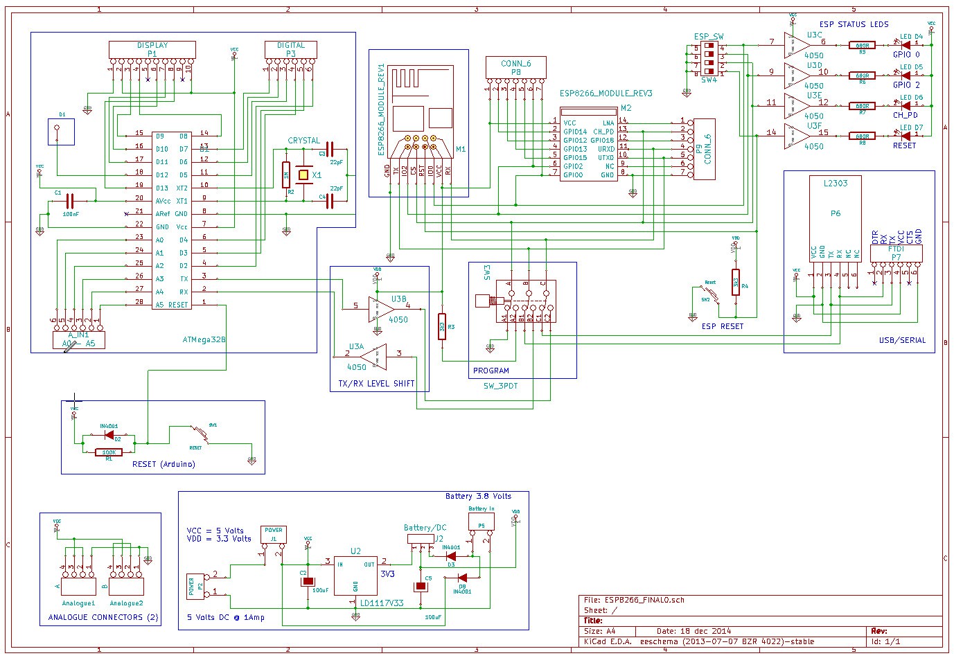
    As part of the testing I want to be able to monitor the ESP8266 pins so I added a buffer and some leds to GPIO0, GPIO2, CH_PD and the reset pin... The two remaining gates on the buffer (4050 IC) are used for level shifting the RX and TX (in the event we have 5 and 3.3 volts supply)....


    Power

    The board is powered from an external 7 to 12 volts power supply (optional battery header with reverse protection, so allow for ~0.6 volt drop)... The 3.3 volt regulator can handle 1.5 Amps.


    Optional Display

    Added header for the little TFT (cost $9 or less) to act as console making the board mobile. Basically anything you echo to console can be directed to the display...


    Programming the ESP8266

    Programming the ESP is accomplished with a little L2303 USB to Serial board and controlled by two switches... A better method might be a 4 pole changeover relay or a single switch if I can find one in KiCad parts... The L2303 is very low cost at less than $2.


    The on-board ATMega 328

    I've added two 6 pin headers, one for free Analogue pins and another for free Digital. There are also two 3 pin headers for connecting potentiometer or sensors etc...


    Miscellaneous

    Added 8 pin header to connect to any of the general purpose Leds (active low, with 680R current limiting resistors)... Added reset switches for on board ATMega and another for the ESP8266 reset pin (in case we need it later)...

    There's a 10 pin header for an optional 1.8" colour display I use for console output and messages in sketches... It only costs $9 and makes the unit portable (if you add a battery)....


    I was positive I added a schematic last night but I don't see it now and the markdown is not behaving?

View all 8 project logs

Enjoy this project?

Share

Discussions

[deleted]

[this comment has been deleted]

Michael O'Toole wrote 06/02/2016 at 20:01 point

I have more ESP modules than you can shake a stick at...

  Are you sure? yes | no

Michael O'Toole wrote 11/03/2015 at 03:56 point

I've been having more problems with KiCad and have to rebuild most designs...  It's probably down to me but for the life of me I can't seem to locate the correct libraries and mod files used in previous designs...  In the mean time an update above...

  Are you sure? yes | no

Michael O'Toole wrote 10/19/2015 at 02:14 point

Hi Craig,

I did intend to add the files to my git repo some time ago but after updating Kicad to the locally compiled version I was missing libraries and 3d images and paths were messed up... I think I have the issues sorted now so will find the files and make sure they are correct before I add them to git... (could even add a card reader to next version... ;)

I will post back when I have everything updated...

Mike

PS... Looks like I have a few boards designed here, which one is of interest?

  Are you sure? yes | no

Craig Hissett wrote 10/19/2015 at 11:51 point

Sorry buddy - you probably explained that perfectly well but I got all giddy excited and probably didn't read everything thoroughly :-)

I am fascinated by all your boards; the ESP8266 is something I have always wanted to get to grips with but lacked the knowhow, but now it is programmable with the Arduino IDE I am eager to get cracking.

The board that has tickled my fancy the most is the one you outlined in your initial plan; the dev board with an onboard ATMega328, and the option to plug in a little TFT screen. Any of the layouts with those features is perfect; as you said in your initial design it only takes the little screen and a battery to make it portable.

If it had a card reader and a a couple of tiny buttons (up,down, ok, cancel?) to enable loading from the card (with the correct bootloader) I'd sail to Ireland and kiss you ha ha!

Even without that, i can't wait to see the updated files. It's certainly moved to the top of the covet list!

Thanks for taking the time to reply!

Craig

  Are you sure? yes | no

Michael O'Toole wrote 10/20/2015 at 04:42 point

I found most of the files and have started to to update them for the current Kicad (mostly fixing paths and adding missing components)...

The program switch I use in the design is impossible to source so that needs changing. 

I'll post all of the designs and let people choose...

  Are you sure? yes | no

Craig Hissett wrote 10/20/2015 at 06:02 point

awesome!

  Are you sure? yes | no

Craig Hissett wrote 10/18/2015 at 17:25 point

i love the concept of this board!

Having recently started wanting to learn more about the ESP board to add wifi to my ATMega projects this board would be a dream come true.

The addition of the screen for debugging and status is a wonderful addition too!

I have always had my heart set on having a small, pocketable prototyping setup and your project nails it; things such as the phoenard (which recently smashed its kickstarter target) are great but extremely costly; your board does everything that i would use the phoenard for, save loading sketches from a microSD card. BUT at the price to assemble your little beauty you could just have one for each project! :-)

Are your files up on a github yet? :-)

  Are you sure? yes | no

Michael O'Toole wrote 03/23/2015 at 16:06 point

Latest news (23rd March)

Small problem with old version of Kicad during the week, managed to loose some work, so updated to BZR 5288 and in process of updating all files...

Picked up a RIGOL DS1052E digital oscilloscope to replace broken scope... I heard good reports about it and have to agree, for the money it's excellent... 50Mhz (1GS)...

Still awaiting parts for next build...

  Are you sure? yes | no

Michael O'Toole wrote 03/18/2015 at 17:31 point

Please note, all files available on request...will add them to git as I get time...

  Are you sure? yes | no

Michael O'Toole wrote 03/16/2015 at 02:33 point

March Updates:

Found a nice Arduino Library, unfortunately the code contains no copyright information and I can't publish code without permission from the author (even if it was provided from a link posted in the publically accessible site)... More on this later...

---

Using an App (free iPhone but may be available for android too), I can control pretty much anything I want to control on the development board or any ESP8266 connected via WiFi. Although I have not tested communication the other way round (ESP to App) I expect smooth sailing...

---

As the ESP rev. 12 module contains a breakout for an ADC pin, I will update some board layouts to accommodate this (might be ideal for some basic sensing applications).

  Are you sure? yes | no

Michael O'Toole wrote 01/21/2015 at 23:09 point

Apologies for delay with projects... Finishing long term phpBB extension and it's quite large and taking up all my spare time...

  Are you sure? yes | no

Michael O'Toole wrote 12/08/2014 at 23:45 point
I'll leave it for a few days and if no requests I will finalise the board... probably the original design with room for adding rev 3 of ESP as the extras in my second revision are not really needed....

  Are you sure? yes | no

Michael O'Toole wrote 12/08/2014 at 22:47 point
There are a few reasons ...

1) It allows you to use inexpensive TFT display and a little additional code to debug without a computer... (ideal when testing around the house)...

2) It frees up your Uno etc., as sketches can be written directly...

3) Programming the ESP correctly is not quite ready for main stream, some more work is needed...

  Are you sure? yes | no

Ian Tester wrote 12/06/2014 at 05:23 point
Why have a separate ATMega when the ESP8266 is programmable? Not enough I/O? Need analog?

  Are you sure? yes | no

Mathieu Stephan wrote 11/29/2014 at 15:45 point
put this on tindie asap!

  Are you sure? yes | no

Michael O'Toole wrote 12/01/2014 at 19:38 point
Perhaps when it's finished...

  Are you sure? yes | no

Michael O'Toole wrote 11/21/2014 at 16:32 point
Would be interested in your comments on your new board as I did plan to buy one... I believe there no English manual but not sure if one is needed... What else does it have?

Our board will differ substantially but it would be nice to see what else I can incorporate...

You might get some info here for STC 15W408AS: https://github.com/SHMIIC/wirelessposi

  Are you sure? yes | no

smiley8088 wrote 11/22/2014 at 04:33 point
You're right, there is no English manual.

I've posted a few photos and some dmesg output here:
http://frogherd.com/esp8266/esp.html
Please forgive the page formatting.

That microcontroller (STC 15W408AS) is another thing for which I can't find any English language documentation.

I'm on a steep learning curve so it might be a while before I get around to doing any real investigation, but if there are any specific tests you'd like to see the results of, let me know and I'll see what I can do.

  Are you sure? yes | no

Michael O'Toole wrote 11/22/2014 at 19:32 point
It will take you time to work things out without a manual...

I can see from the images most of what available but if you notice anything unusual or useful that we could add it to ours, let me know...

As they are low cost I guess I could buy one as an early Christmas present for myself but it will take a couple of weeks to arrive ;)

  Are you sure? yes | no

smiley8088 wrote 11/21/2014 at 12:17 point
I got one of these cheap ESP8266 development boards in the post yesterday, I haven't done much with it yet except switch it on and push some tact buttons, but if you're interested in seeing some better pictures of the board, let me know.

Here is the listing I bought from: http://item.taobao.com/item.htm?id=41548063506

  Are you sure? yes | no

Michael O'Toole wrote 11/15/2014 at 03:10 point
I found a fairly good supplier yesterday but it's been a long time since I produced a board for manufacturing so I'm guessing when finished I will ask for help getting it right...

The only thing I nailed down in the design (worked on it all day) is the fact that from the flick of a switch it changes from testing to program mode... If we go with the on board ATMega328 I will use a ZIF as they only cost $2.... I'll add some ideas after some sleep ;)

  Are you sure? yes | no

davedarko wrote 11/15/2014 at 03:14 point
I'm following this and hope I can help at some point :) Good luck and good night!

  Are you sure? yes | no

davedarko wrote 11/15/2014 at 02:57 point
have you considered using http://dirtypcbs.com/ ? i never tried them but the prices seem awesome! I'd love to see a board where you can easily change the firmware and access the normal serial functions, and it should fit on a breadboard.

  Are you sure? yes | no

Similar Projects

Does this project spark your interest?

Become a member to follow this project and never miss any updates