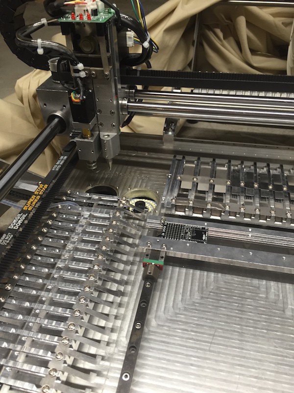
-
Software and vision fussiness
10/19/2015 at 17:03 • 0 commentsIt's been about 3 months since I updated, so I wanted to let people know the current state. Two things have cropped up recently: the machine software and the vision.
Software - no software updates. I'm not really surprised and I suspected I wouldn't get any going into this purchase. But there are bugs and it would be nice if there were updates to fix them. But, unfortunately, having spoken to the company, this is just not going to happen. Looks like they might have had a falling-out with their original software provider. I've not yet tried to contact the software maker directly, but I will probably do that at some point.
Vision - the vision has been particularly fussy recently. I'm not sure why this would be. The machine does align and center components correctly using the vision system, but it then mis-rotates before placing (usually over or under rotates slightly). I need to revisit the configuration here to see if I can work out how I made this worse. Until I have time to investigate, I've found placing without vision to be more accurate (which is just wrong, really).
-
Just so you know ...
07/16/2015 at 23:31 • 0 commentsThe other day someone emailed me to ask if I still liked my SMT50 and would I still recommend it. I think they wondered why I'd not updated this blog recently, which is a fair observation. So; yes I still like the machine and still recommend it. I've not written much here recently because I've not had much to add - it works, I'm happy and haven't had to do much more tweaking.
So ... now you know.
-
Component rotation
01/14/2015 at 22:22 • 7 commentsWhen I started using the SMT50 to place my first board, I didn't really have component rotation setup properly in the Eagle source files. To get it working I just messed with the Part rotation in the PCB on the SMT50 until it was placed correctly. Not really the way to go, but at the time it was one less thing for me to sort out properly.
I finally had chance to look at rotation properly today (I know ... it's been a while) and things are not as helpful as you might hope. There are three sources of rotation information which might be used when picking and placing a part. The first is the location of the tape; either in the north feeder or the west feeder. These feeders are at 90 degrees to each other, so tapes loaded in different feeders start with different initial rotations. Next, each feeder has the ability to set its own rotation as part of the feeder configuration. And finally, the parts themselves also have rotations which may be set.
After some experimenting I was rather surprised to discover that the only rotation that matters is the one set on the part itself. The position of the feeder is ignored, as is the rotation set on the feeder. This means that, after you load your pick and place file into the machine, you need to very carefully check every rotation of every part because which tape the part is fetched from is not taken into account when rotating.
Oh, and don't forget; the PCB itself can also be rotated depending on how you load it into the machine which will also effect the value you set on the part rotation.
One final detail. Rotations are anticlockwise looking from above.
-
Vision Tweaking
11/29/2014 at 07:04 • 0 commentsOne of the major reasons I purchased this particular machine was for its vision system. The device comes with two cameras; an upwards facing fixed camera, and a downwards facing camera attached to the mount. The down camera is used for various things, but the up camera is only used for component centering.
For my BlueBasic project, I have a very small boost converter chip (2mm by 1mm) which is packaged a little loosely in its tape. After some initial experimentation without vision it became clear that I needed vision to accurately place this device. However, despite my best efforts, I could not get the vision system to recognize the chip. I tinkered with the light, I changed the various vision settings, I tried masking the camera in different ways, but nothing worked reliably. Occasionally the vision system would do the right thing, but then would stop.
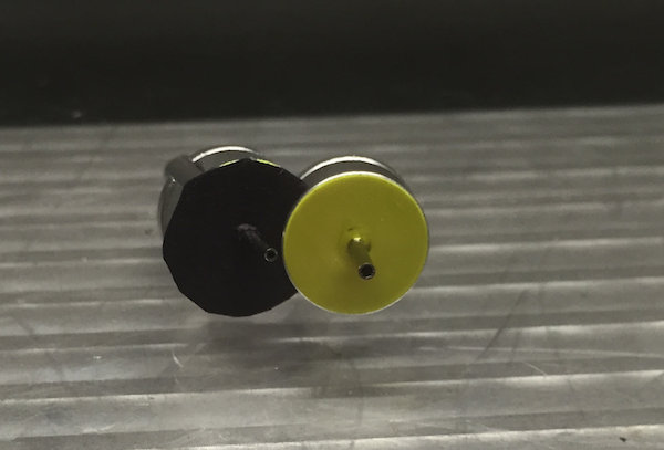
Eventually, after watching the (then untranslated) videos several more times, I noticed that all the vision examples used a larger nozzle, while I was using a smaller one. That didn't seem so significant except that the small nozzles had a yellow background, while the large ones have a black/grey background. I'd originally assumed that a black chip against a yellow background should be fine, but in my desperation I put a disc of black paper over the yellow and tried again. And it all works! Here's a before and after photo:
![]()
So, I don't know why any of the nozzles have yellow background, but I suggest you replace them with black paper.
One other note - once the Vision video was translated, about 30 seconds in they tell you this fact! Oh well.
12/2/14: A late addition. Apparently I'm a bit blind because on the front of the machine are three little dials. Turning them changes the light intensity. Wish I'd noticed earlier.
-
Video Instructions
11/27/2014 at 06:50 • 0 commentsNow, a little diversion from my own blogging about the SMT50. When you buy this machine it comes with a whole set of instructional videos ... narrated in Mandarin :-( Watching them it became clear they contained lots of very useful information if only I could understand what was being said.
So, off the Craiglist I went to find a translator. And there I found a very helpful chap called Tony who has been working to provide time coded transcripts for each video. You'll find these videos, with transcript, on YouTube here:
youtube.com/watch?v=EoyQQapnzf4&list=PLoOObN3KOYWWzeCRNp3L8-0Fs4PbKlDCG
I hope you find them useful.
-
Speed Settings
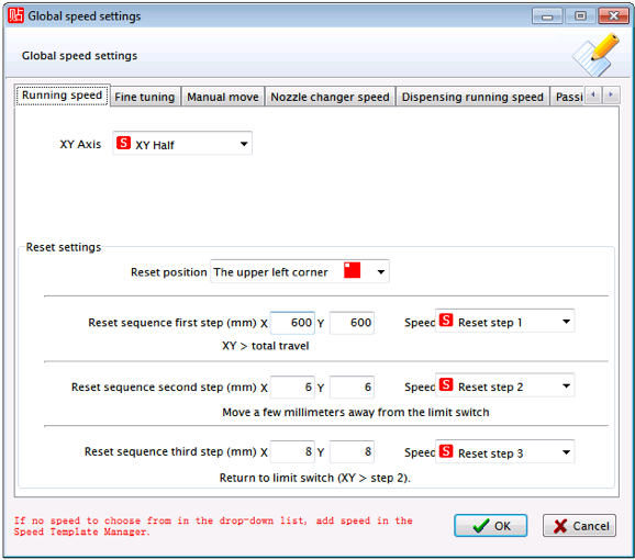
11/23/2014 at 06:35 • 0 commentsThe other parts of using Speeds is assigning them to various operations. This is done in the "Speed Settings" window which is also available from the "Config" menu option. This is a multi-tabbed window with each tab allowing you to set specific speeds for various operations:
![]()
Notice in my settings I've changed the XY Axis (the general pick and place running speed) to my "XY Half" setting. All these settings are completely sensible and there's no reason to change any; but it's interesting to explore and get an idea of how you might tweak the machine to better results. Notice the tab "Dispensing running speed" which I assume is for machines with adhesive dispensers (which the SMT50 doesn't have).
-
Speed Management
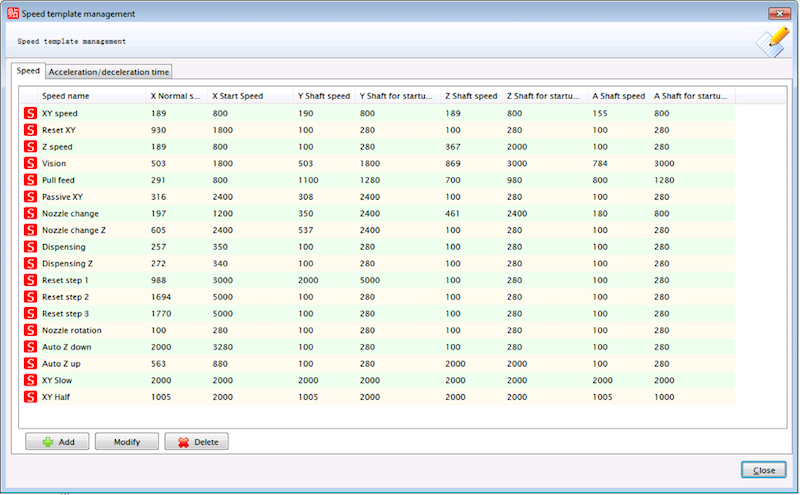
11/23/2014 at 06:24 • 0 commentsThere are lots of different operations that the head of the machine performs, and each of these can be configured to a specific speed. The speed settings are separated into two sections: a configuration for a specific speed setting in terms of how fast the move the various stepper motors, and when that setting should be used. Going back to the "Setup" menu, you'll see two Speed options listed. If you open the "Speed Template Management" option you'll see this:
![]()
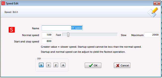
Actually, you'll see this is you first replace the speed.ini file (which, again, has improved translations). Of all the speeds in this list, the most important one is the first, the "XY speed". If you select it and hit the "Modify" button you'll see this:
![]()
This speed is the one the machine uses for almost every pick and place action. By selecting the X, Y, Z and A at the bottom/left you can view and edit how each of these axis stepper motors are handled. As the dialog says, larger values results in slower movements. Also, be aware that specifying values which are too fast, especially for "Start and stop speed" can result in the head failing to operate properly resulting in lost of accurate position. This occurred to me when I accidentally changed the "A" value to be too fast which not only prevent the component being rotated correctly, but also mean the head miscaculated the next X position.
At the very bottom of the speed template list you'll see two additional speeds which I added to my configuration. The "XY Slow" speed has all the value set as high as possible to everything moves as slow as possible. It's quite handy for testing.
-
Tapes
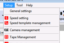
11/22/2014 at 05:07 • 0 commentsTapes go in the feeders and need to be configured separately. You find the tape configuration under the Setup menu on the top bar:
![]()
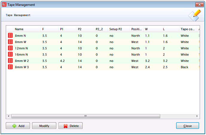
Selecting Tape Management opens a pane something like this:
![]()
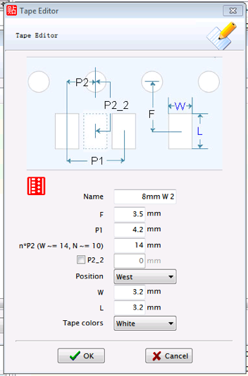
Here I've defined a few tapes. Tapes can be added, modified, or deleted using the buttons at the bottom of this window. To Modify a tape, first select it. Here's a tape I'm currently using:
![]()
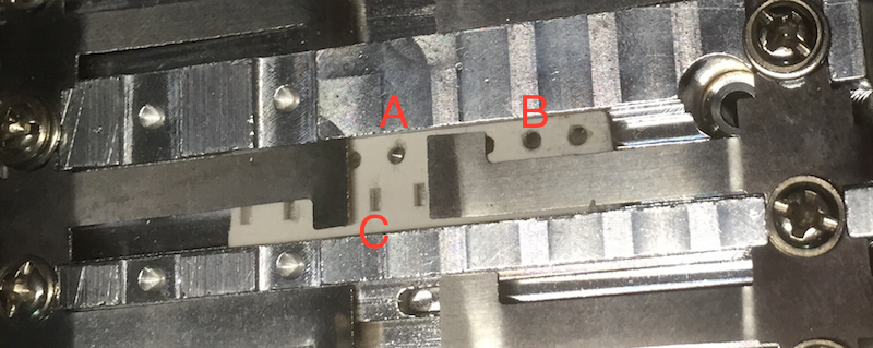
As you can see, tapes have lots of properties. But, if you look at a tape's spec, you should find measurements given for all of these properties. I've tried to pick a name which is, at least in part, meaningful to me. I've included which side of the machine this tape will go and made sure to set the Position appropriately. This is *very* important! If you get this wrong, the machine will attempt to pull the tape in the wrong way and make a terribly noise as it does it (take it from me!). Also be careful with the n*P2 value. P2 is the distance from the middle of the component cavity to the tape sprocket hole. Initially I just used the value for my tape (which was 2mm). This is bad. Here's a picture of a feeder with a little snippet of tape in it:
![]()
"C" is the spot where a component, and "A" is the feeder hole a distance P2 from it. When the tape advances, the head will drag it a distance of P1 (the distance between two holes). However, if it drags from "A" it will attempt to move the head into the metal flap to the right of A. Again, the machine will make a very bad noise! Instead you should set P2 so it will drag from hole "B". In my case that was 10mm for the North set of feeders, and 14mm for the West. I changed the translation from a simple label to try to remind myself of this fact.
One final value for a tape is the color, which may be black or white. So far I've not found if this is used in anyway.
-
Feeder configuration
11/22/2014 at 03:02 • 1 commentThe basic machine comes with a west feeder consisting of 20 8mm feeders. I added an additional north feeder which comes with an assortment of 8mm, 12mm and 16mm feeders (I like to have options!). I'd watched the videos and, looking at the machine head, I could see the pointer head which was used for dragging the tapes through the feeders. But how does the machine know where the feeders are?
![]()
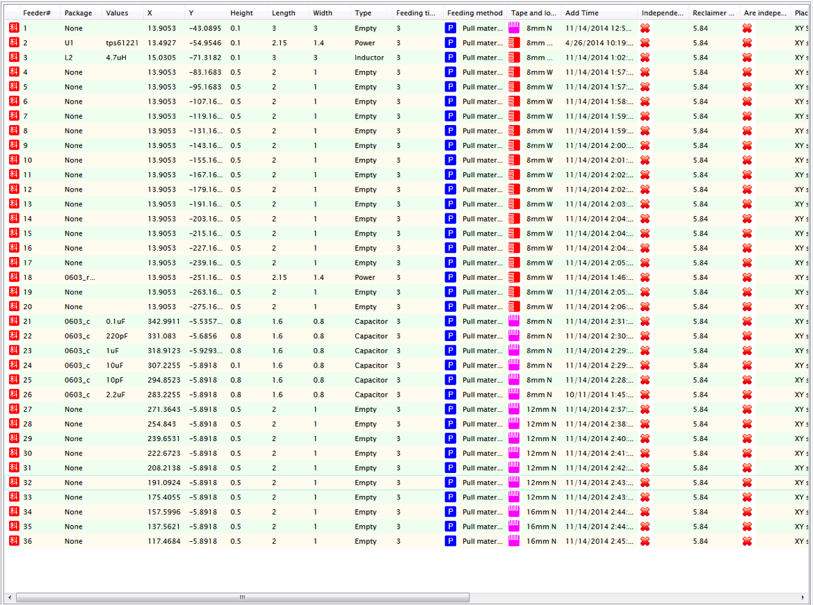
On the top bar of the app you'll find a button "Feeders" (or you will if you're using my translations). Pressing that opens up the feeder pane. This one shows many feeders already configured:
![]()
As I recall, the default project which comes with the machine only defines two of the 36 available feeders; the rest you have to define by hand! This isn't that hard to do once you've worked out how to move the machine head around and have the MARK camera working. However, it is rather tedious. As a starting point I've added my feeder configurations to the GitHub repo. These are part of the project database and you can find if here https://github.com/aanon4/SMT50/blob/master/OURSMT/config/Project_smt.cfg. When it comes time to use an actual feeder for components, you'll probably need to tweak the values a little depending on the tape properties, component size, etc. To do this simply right click on the feeder line and select "Modify feeder" from the popup menu.
Feeders are number 1-20 north-west to south-west, and 21-36 north-east to north-west. This isn't that sensible really, but it fitted with the numbering scheme of the two originally defined feeders and, at the time, I thought the numbering might be significant. It isn't, and you can number them anything you want.
Modifying feeders
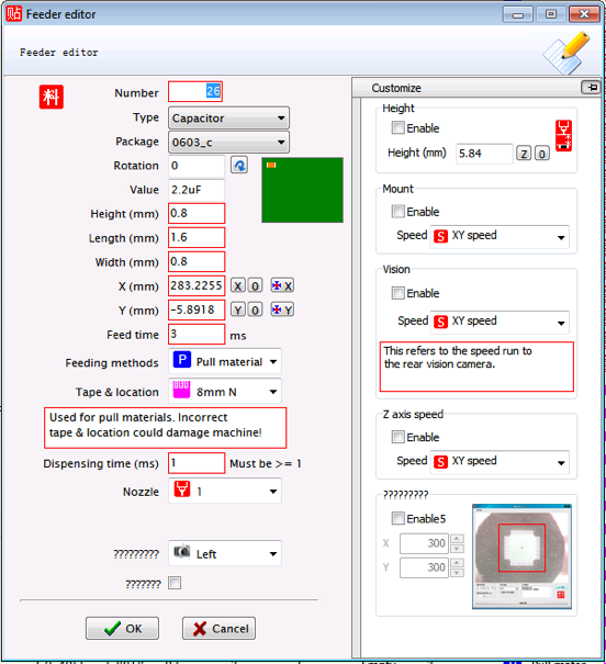
The feeder modification popup looks like this:
There are lots of things happening in this window and, as I write this, I don't know what all of them are for. In the context of just feeding the component, the X, Y, feeding method and tape & location settings are most important. The X,Y set the exact position of the pick nozzle over the component and should be as central as possible. The feeder method and tape & location settings together define how the tape of components is handled (i.e. how the tape is advanced to the next component). All feeders on the SMT50 use the "Pull" method. Tape and location is defined in another settings window which we'll talk about next.![]()
-
Machine movement basics
11/21/2014 at 22:02 • 1 commentEventually I'll get transcripts done for the instructional videos; but in the meantime it can be tricky working out how to do things. Take just moving things around. When you open the software, there's a big "Connect" button on the bottom(ish) left. Press this and the software will connect to the machine. Once connected it's time to make sure everything works. The machine has 4 different controls for the pick and place head:
- North/South
- East/West
- Up/Down
- Rotate
![]()
The machine places South at the front of the machine, North at the back, West to the left, and East to the right. Also, North/South is the Y-axis, East/West is the X-axis, Up/Down is the Z-axis. and Rotate is the A-axis. The different axis names and compass points come up frequently in the software.
You can move the machine along these various access using the on-screen buttons on the middle/left of the window. The labels and what they do are mostly obvious. There are also keyboard shortcuts to manipulate the machine. You can glean these by watching the videos (several times in my case) or just read my list here:
- East - LEFT
- West - RIGHT
- North - UP
- South - DOWN
- Head down - PAGE DOWN
- Head up - PAGE UP
- Rotate - END and HOME (clockwise and counter-clockwise ... I don't recall which is which)
Initially I missed that none of these key will do anything unless you also hold down the ALT key at the same time. You can also make more fine adjustments by holding down the ALT and SHIFT keys.
SMT50 pick-and-place
Describes my experiences buying, setting up, and using the SMT50 pick and place machine
 Tim Wilkinson