-
The Finished Product
12/28/2014 at 23:03 • 0 commentsOr nearly finished I should say, as I'm still on the hunt for some nice shiny red potentiometer knobs
![]()
-
Component Installation
12/28/2014 at 22:46 • 0 commentsHaving soldered in excess of 400 wires to buttons and various connectors, an acrylic shim is created to mount the Arduino Due, Speaker, LCD display and LCDs to. The pushbuttons and keyswitch mounting are used to bolt the shim to the hammond enclosure, while preventing the pots from rotating. A similar approach is used for the BNC connectors and Fibre transmitter to lock their rotation.
![]()
During testing of the prototype, there was a bit too much noise present on the output of the potentiometers. As a precaution, some extra caps were ninja'd onto the potentiometer outputs (there are already caps on the shield too).
![]()
What the enclosure looked like with the shim and I/O installed
![]()
![]()
LCD and remaining components installed, with all the wires routed, crimped, and connected to the board.
![]()
The small, 3D printed red plastic component above the LCD houses the status LEDs (Keyswitch, Interlock and Gate)
![]()
-
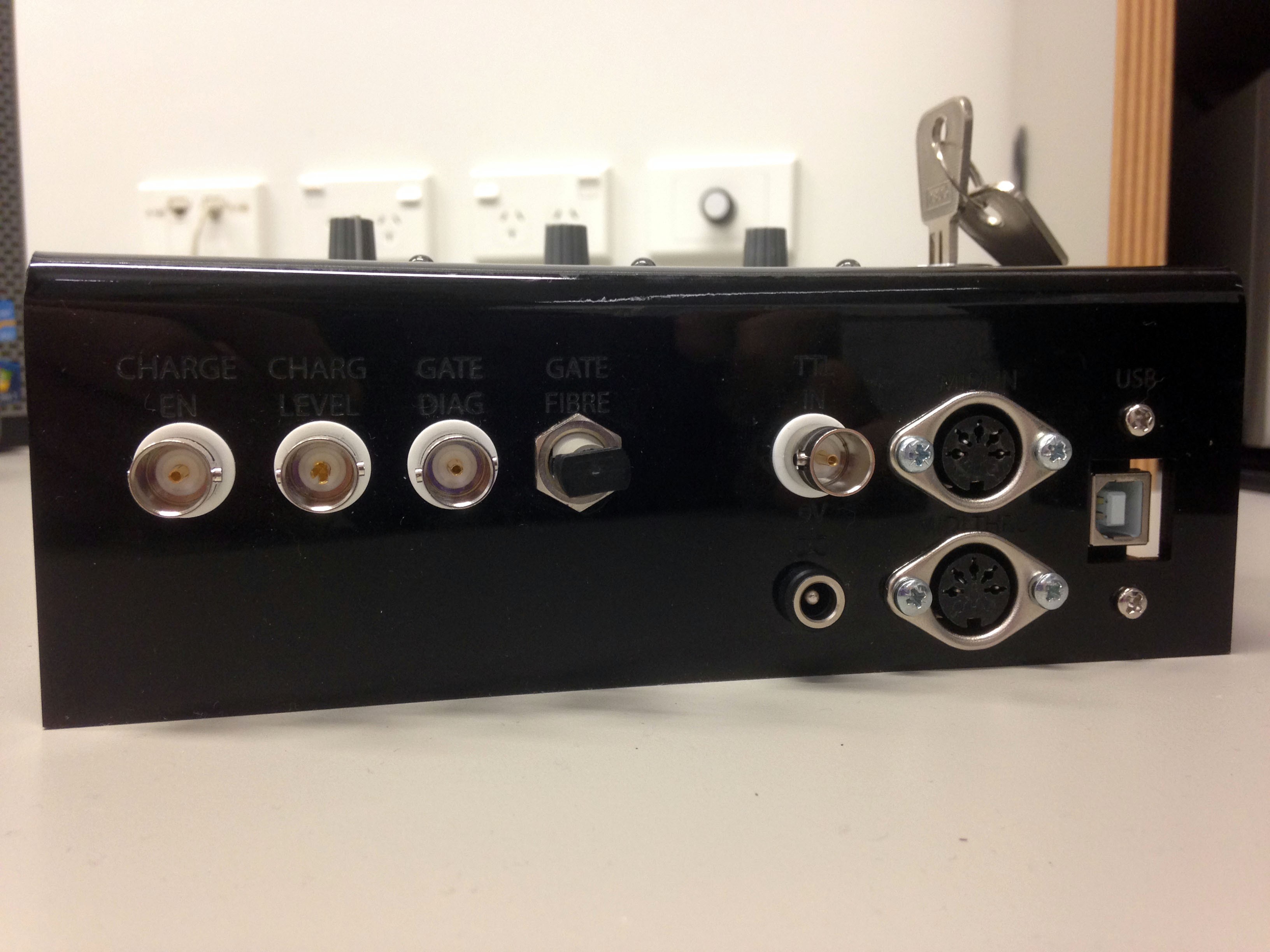
"Bombproof" Enclosure
12/28/2014 at 22:27 • 0 commentsThe final "bombproof" enclosures for CHIME RED are Hammond Die Cast Aluminium Enclosures. Aluminium boxes were used to provide RF shielding of the internal components, while a black powder coated model was used to allow for laser engraving of labels.
One the required interface and I/O layout features had been modelled in SolidWorks, the hammond enclosures were CNC milled
![]()
Next, text labels were laser engraved on the enclosure. Careful alignment of the enclosures in the engraver was done using dry runs of the engraver tracing out the milled features using the visible red dot.
![]()
![]()
-
The Prototype
12/28/2014 at 22:17 • 0 commentsBefore building the final CHIME REDs, a fully functional acrylic prototype was created to test the system design with live Tesla Coils.
![]()
![]()
![]()
-
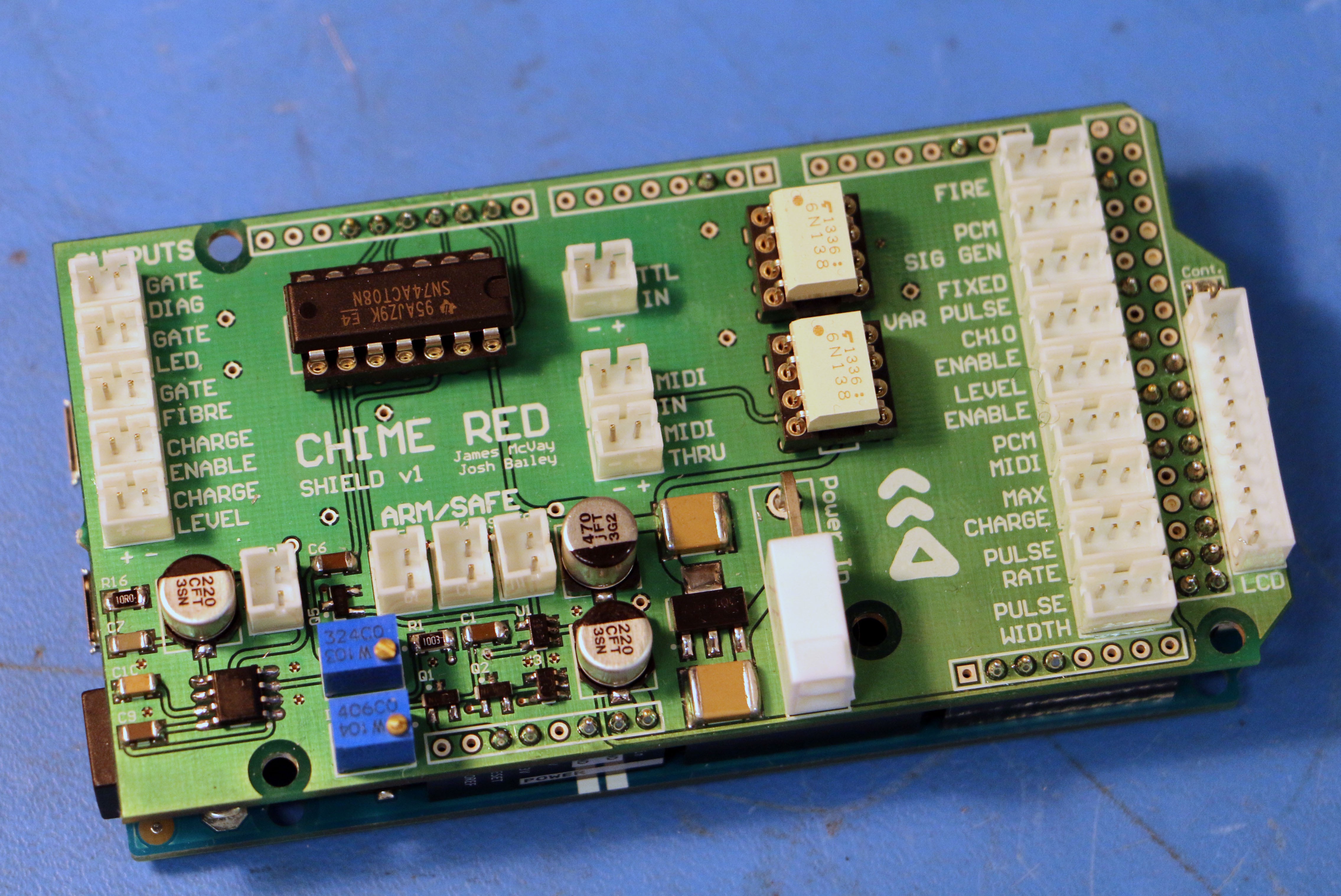
The Completed Arduino Due Shield
12/28/2014 at 22:09 • 0 commentsThe Populated Arduino Due Shield, mounted on a Due.
- AND gate to prevent outputs from being triggered when the interlock isn't engaged as well as driving the TTL outputs
- Interlocked based on Keyswitch Input and RC + Schmitt Trigger Oneshot (Due outputs flail on Startup)
- Amplifier for Speaker Output to Simulate Gate Output at Bottom LHS
- Potentiometers control Speaker Volume and Interlock Startup Delay Period
- 6N138's for MIDI Input and Optoisolated TTL Input
- 2 Pin Connectors for Gate Fibre, Status LEDs and TTL Outputs on the LHS
- 3 Pin Connectors for Push Button Inputs as Labelled on RHS
- Status LCD connector on RHS with Contrast Pot above
![]()
CHIME RED
A Collaborative Project - Building the Hardware for a MIDI Telsa Coil Controller capable of 16 simultaneous Voices