Close
0%
0%

3D Printable Robot Arm

A printable robot arm, a little bigger than the usual hobby servo once.

Similar projects worth following
My printable robot arm is inspired by the well known industry robots, but printable.
The goal is to develop a open source robot arm to use in private or small businesses and make robot development available for every one.
The arm should lift about 2 kg enough to perform every day tasks. Currently robot arms are expensive or small and weak, or clumpy.
Industrial robots are expensive and dangerous and for that not suitable for using at home or schools.
A Open Source printable robot can build,used and developed by every one.
Robots are still expensive and hard to operate, but this must not longer be the case.
A cheap 3d printed robot arm could be used by disabled persons to manage their daily needs better and more independent. Operate at dangerous but not so developed places.
Remote controlled you could even us the robot to open your door if you forgot your keys.

The future Arm will include a moving base.

That's where I'm currently heading ( My 2019 ) :
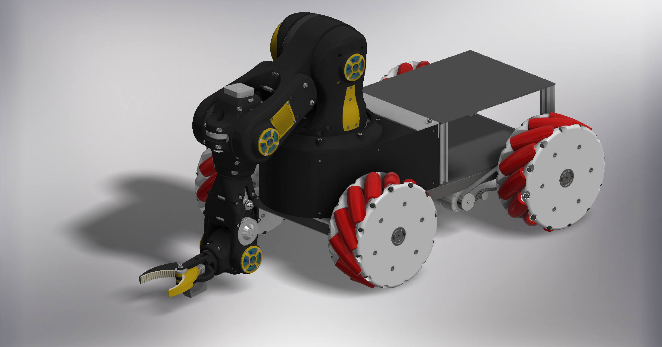
The four robots I build since this project started.
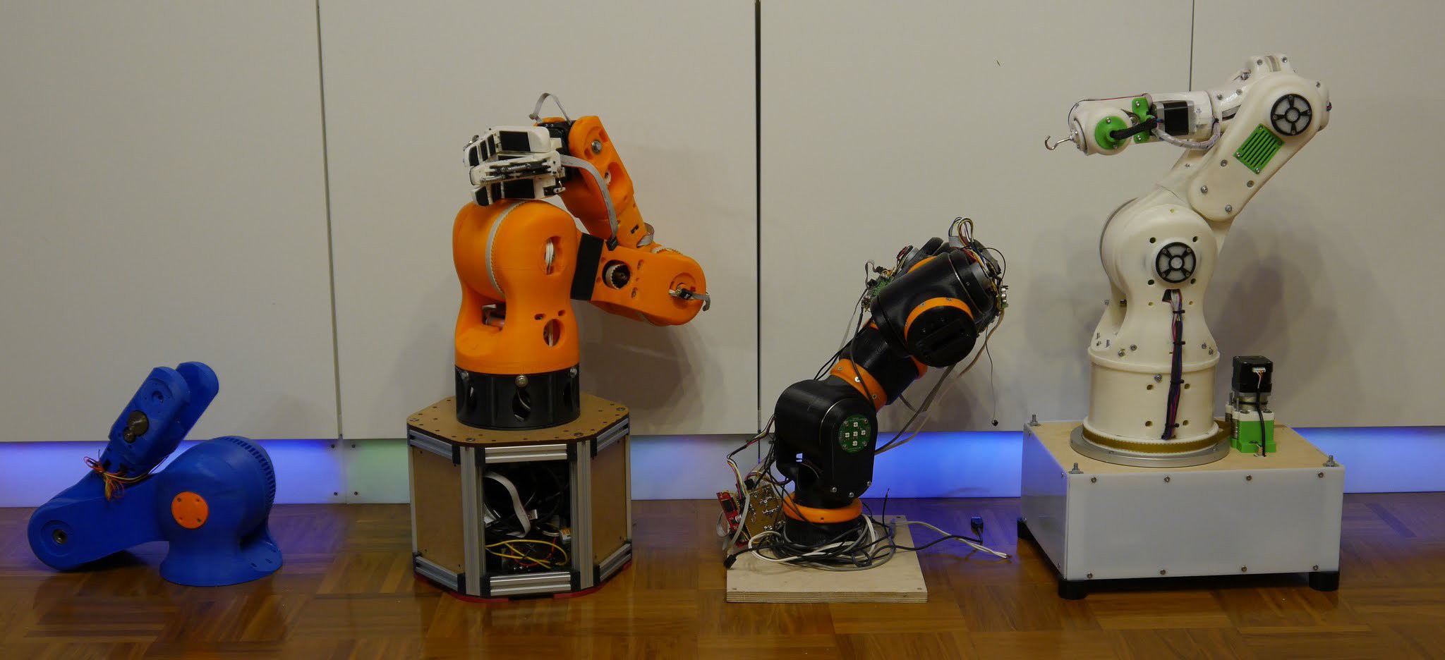
Version 4 now nearly done and in testing.

Take a look at the Gripper I designed for my Robots:

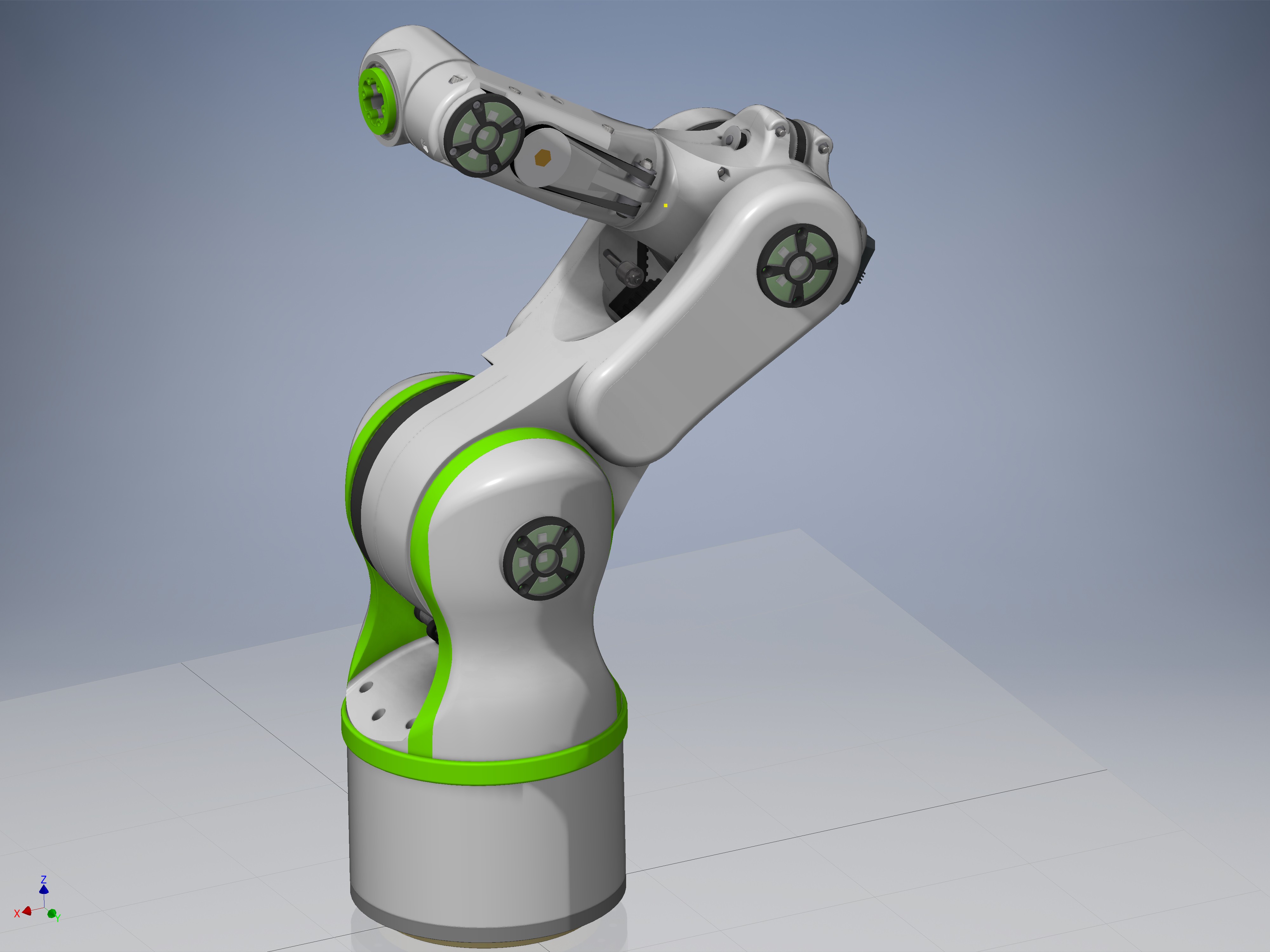
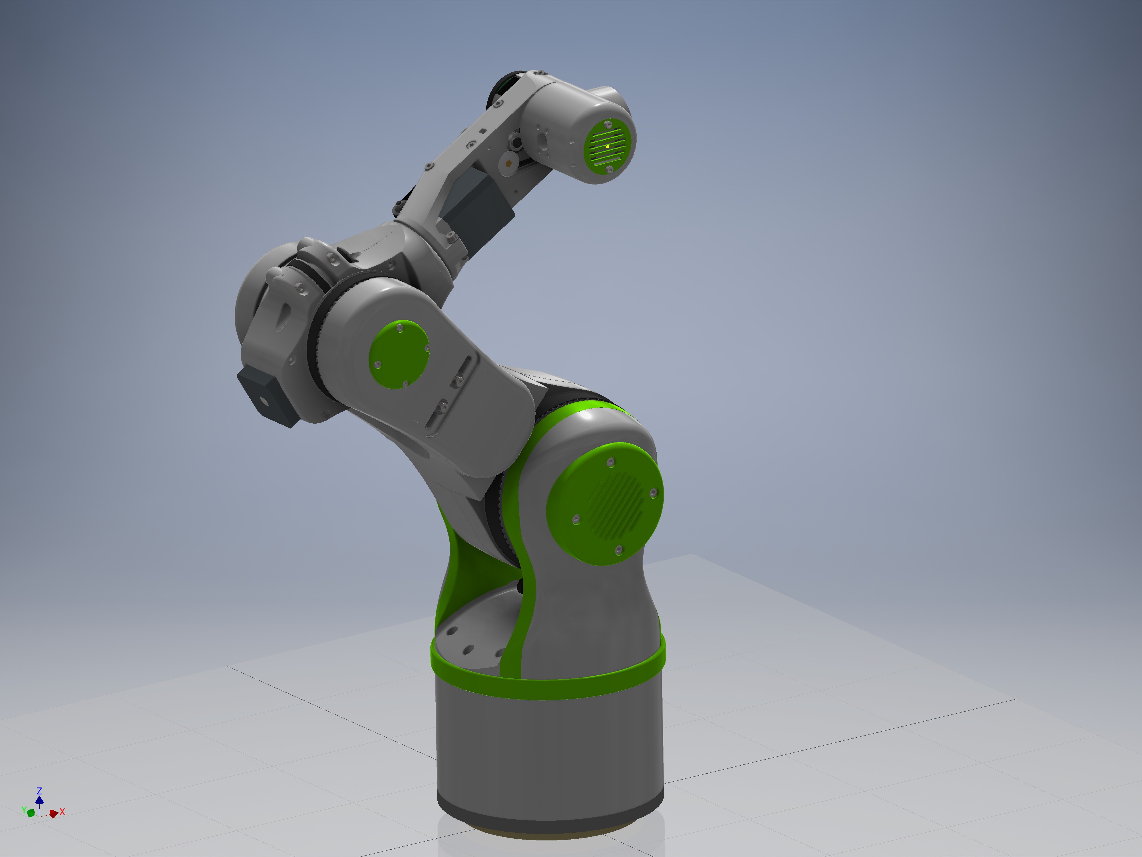
Version 4 is now nearly complete:

I also started uploading the files on github:

https://github.com/4ndreas/BetaBots-Robot-Arm-Project

And a components list for version 4:

http://1drv.ms/1NIofNR

  • 1 × Version 4 BOM see the link to the excel file: http://1drv.ms/1NIofNR
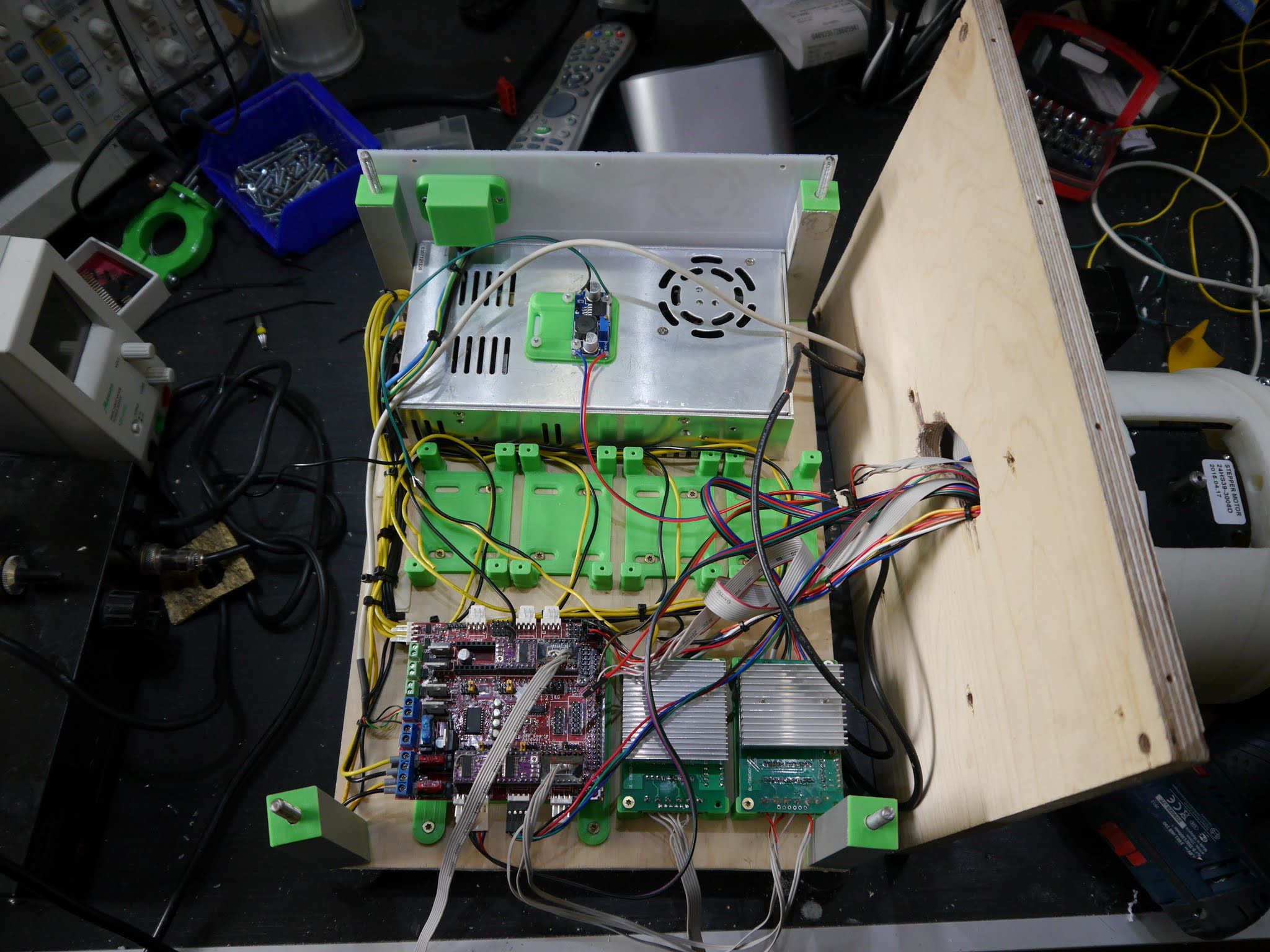
  • 1 × 24V - 200 Watts (or more) Power supply
  • 1 × Arduino due + Ramps+FD shield I use this until I have time to design my own shield
  • 5 × suitable stepper motor driver I used TB6560 Stepper Motor Driver Boards

  • 2019 Update

    Andreas Hoelldorfer05/12/2019 at 16:51 2 comments

    It's been 4 years since I started this project. Its had some downs and a lot of ups. Time to give you an update about whats going on.

    Notice: "No robots were harmed during making this video."

    I post regular updates on my Instagram feed if you are interested in faster updates: 
    https://www.instagram.com/4ndreash

  • Mantis IK in Robot Overlord

    Dan Royer05/10/2016 at 16:35 2 comments

    https://www.instagram.com/p/BFNmSFqofN_/?taken-by=imakerobots

    The link above is a video of the working inverse kinematics. Now I don't have the arm on my desk, so I can't write the firmware that ties the arm to RO. However! RO is ready to connect and talk with Mantis.

    My interest is drifting towards easier ways to move the arm in VR. The more I use RO the more I want to fly like an FPS game and push/pull the virtual model rather than click buttons on the side.

  • Robot Overlord support for Mantis

    Dan Royer05/04/2016 at 19:23 4 comments

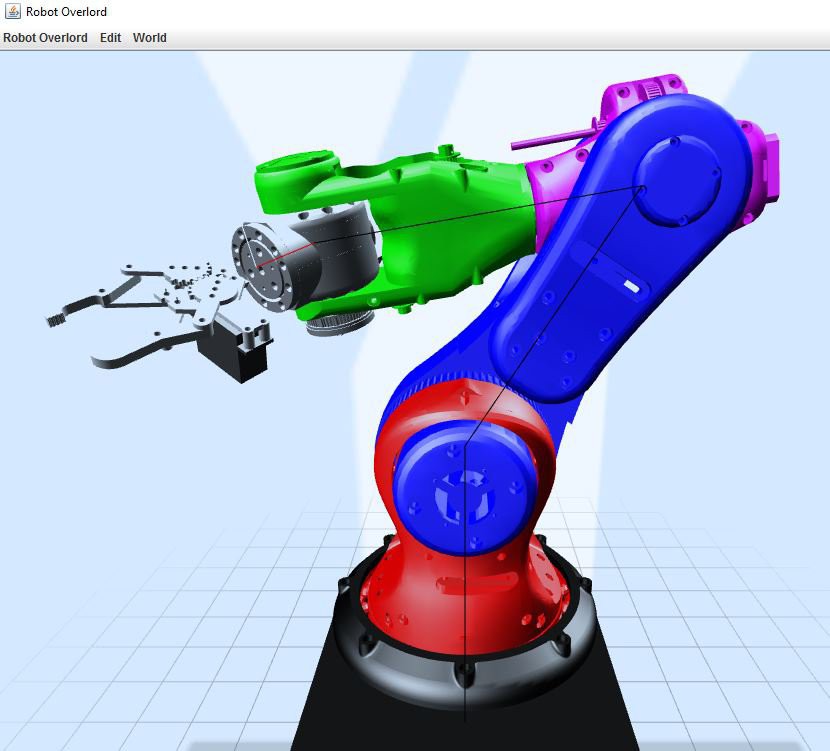
    Hello Everybody! Dan Royer here. You may know me from helping such projects as the PancakeBot and the Cypress Umbrella. Glad to be working with @Andreas Hoelldorfer. He's got the hardware and I've got the software, so it will make a good team. Above you see the latest version of Robot Overlord (RO) simulating the Mantis arm. RO is a robot simulation package I've written in Java. Think of it as my One Ring.

    First stage was to port the Inventor models into the system and animate them. The line you see running through the model is the software's mental model of the forward kinematics (FK). The FK informs the rendering engine where to draw the parts of the model AND it lets the software check for illegal/impossible arm moves. FK means "if my joints are at these angles, tell me where is the finger tip."

    Second stage will be to get the inverse kinematics (IK) working. IK is the other direction - "I know where the finger is, tell me where the joint angles need to be." It will be a naive solution full of singularities because I'm only marginally clever (MC). Sigularities are cases where there may be many valid solutions, and picking an answer is hard for a computer.

    Third stage will be firmware to make this arm talk with RO like all MC robots.

    More generally, MC is working on adding Vive VR support and record/playback to RO. That will mean telepresence work, gamification, and more.

    Dan out!

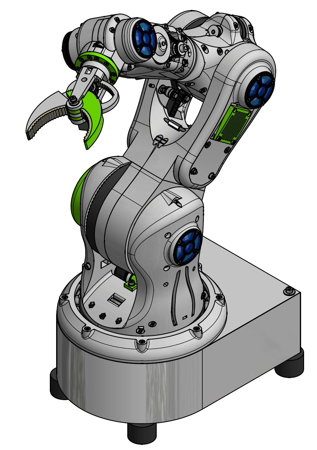
  • I started with a new version called Mantis

    Andreas Hoelldorfer04/13/2016 at 08:11 0 comments

    After version 4 (green) works quite well. I decided to stick with the basic design and improve this version instead of trying another approach.

    I started with the Gripper and will work from top to bottom down the robot arm

    http://chaozlabs.blogspot.com/2016/04/mantis-robot-arm-part-1-gripper.html

    I will post a video about the part and a small article on my blog where all the links and part lists will be.


  • Still here

    Andreas Hoelldorfer02/29/2016 at 17:32 2 comments

    I just posted a update about my 3d printed, 6-axis robot arm project:

  • All in motion

    Andreas Hoelldorfer10/19/2015 at 07:24 5 comments

    All six axis of my robot arm are moving now:

    I build a case for the electronics, nothing special but it will serve the puropse.

  • 3-Axis running and detailed description of the arm.

    Andreas Hoelldorfer10/04/2015 at 09:55 1 comment

  • Working on Version 4 - Progress

    Andreas Hoelldorfer09/24/2015 at 12:47 3 comments

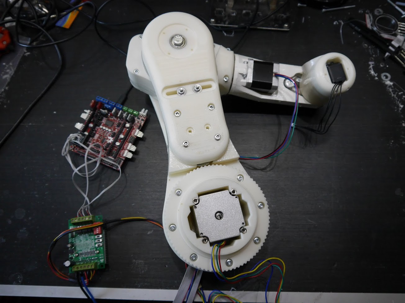
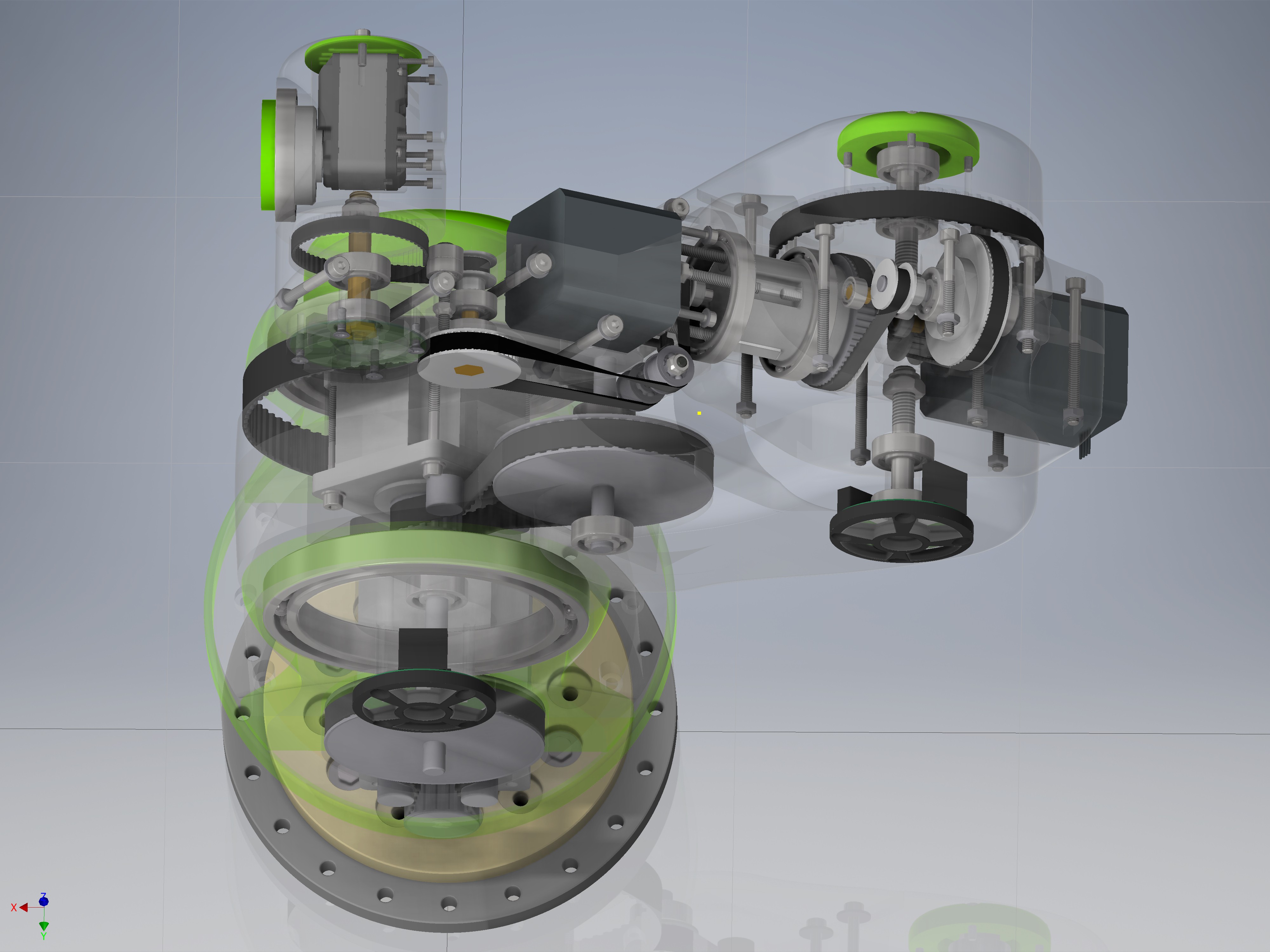
    I use now Nema23 steppers a high power stepper driver and a Arduino Due board with a Ramps-FD shield. I plan to build my own shield but this have to wait a little bit. I defiantly will stick to the Arduino Due. For now the Ramps-FD shield works fine and its quite cheap (25€).

    Currently I'm waiting for the large bearings to arrive, they are not so easy to find. In the meantime I started wiring all up, the cable tubes inside seams to work this time so less ugly cables.

    Everything looks very pomising now I'm very happy with the new design and looking forward to the all in action.

    The only thing left is the rotating base. I try to get the construciton done this weekend.

    I also uploaded step files on github so you can take a look on the arm.

    https://github.com/4ndreas/BetaBots-Robot-Arm-Project/tree/master/Green/step

    Also all other inventor files are online.

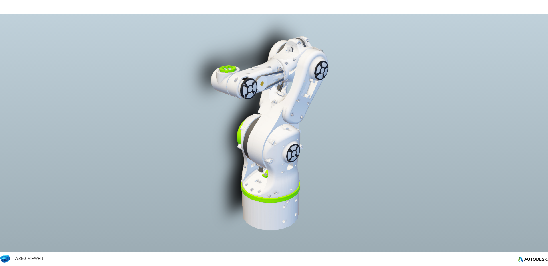
    For those who have no CAD I uploaded the robot A360Viewer an online cad viewer:

    http://a360.co/1gQUnjT

    I tried Onshape but it had a problem viewing all the parts???

    I regularly upload pictures in this here:

    https://goo.gl/photos/ZQA8tRJFSAAc8pZQ9

  • Working on version 4

    Andreas Hoelldorfer09/19/2015 at 11:36 6 comments

    Here is my new Video of the robot arm project:


    I also started uploading the cad files on github:

    https://github.com/4ndreas/BetaBots-Robot-Arm-Project

    Still a mess I try to clean it up in the next weeks.

  • Working on Version 4

    Andreas Hoelldorfer09/11/2015 at 20:46 9 comments

    I'm working on a new version based on the experience I made with the previous versions.

    The plan is to use stepper motors and timing belt gears.

    The plan is to use a Nema23 stepper for the rotary base,

    Joint one and two will be Nema24 ( this: http://www.omc-stepperonline.com/dual-shaft-cnc-stepper-motor-nema-24-100mm-4nm566-ozin-24hs393008d-p-388.html )

    Joint 3 and 4 Regular Nema17 stepper and for the 5 joint a HerkuleX DRS-0101 .

    But nothing is final now.

    Power supply will be 24V-36V I guess.

View all 19 project logs

  • 1
    Step 1

    Print all parts and assemble them ;)

View all instructions

Enjoy this project?

Share

Discussions

Anton wrote 10/20/2015 at 06:46 point

Your robot arm seems to work well enough to be able to repair itself. At least it should already be possible to teleoperate one or two arms to command a computer-controlled repair mission. I imagine it's possible to design a simple process which replaces a damaged timing belt, all within a reasonable amount of time and with minimal human input. Thanks for sharing the source files!

  Are you sure? yes | no

garylcyhk wrote 10/11/2015 at 08:11 point

Great project! Would you mind share more information on the harmonic drive, why it's not working for your project? Thank you!

  Are you sure? yes | no

Andreas Hoelldorfer wrote 10/13/2015 at 06:07 point

bottom line is: They are running not smooth. But if I have a little Time left I will do a full review. 

  Are you sure? yes | no

garylcyhk wrote 10/13/2015 at 15:34 point

Ok! Thanks! Most industry robot uses harmonic gearbox with servo stepper, I am trying to find a all metal harmonic gearbox for robot arm but they're quite expensive. Good day!

  Are you sure? yes | no

madivak wrote 10/09/2015 at 11:14 point

do u use solidworks for doing ur designs?

  Are you sure? yes | no

Andreas Hoelldorfer wrote 10/13/2015 at 06:03 point

No, I use Autodesk Inventor.

  Are you sure? yes | no

Martin Vincent Bloedorn wrote 10/06/2015 at 03:27 point

Hey! Super Projekt! Glückwunsch :) Ich habe die BOM angeguckt, aber konnte das richtige Modellinfo über die Encoders nicht finden (sorry, falls es doch da ist). Sie haben den Link fürs AS5045 gepostet; das ist aber nur ein Integrieter Schaltkreis, oder? Haben Sie die Encoders selbst mit einem Magnet gebaut? Konnte es irgendwie nicht nachvollziehen. 

(Auch, sorry wegen meinem Deutsch. Danke im Voraus!)

  Are you sure? yes | no

Andreas Hoelldorfer wrote 10/13/2015 at 06:06 point

Ich habe die Encoder selbst entworfen du kannst hier die Schaltpläne downloaden:

http://www.thingiverse.com/thing:639329

Ich werde demnächst wieder ein paar Platinen herstellen lassen. 

Die Encoder basieren auf dem AS5045B IC, und dem vom Hersteller empfohlenen Magneten. http://ams.com/eng/Products/Position-Sensors/Magnetic-Rotary-Position-Sensors/AS5045B

  Are you sure? yes | no

Martin Vincent Bloedorn wrote 10/14/2015 at 15:00 point

Cool, werde ich mal anschauen. Danke! 

  Are you sure? yes | no

Dan Royer wrote 10/04/2015 at 18:43 point

How will you maintain belt tension over time?

What precision are you encoders?

  Are you sure? yes | no

Andreas Hoelldorfer wrote 10/04/2015 at 22:24 point
Most of the belts have tension screws, so no problem. The encoder are 12Bit. 
(http://ams.com/eng/Products/Position-Sensors/Magnetic-Rotary-Position-Sensors/AS5045)

  Are you sure? yes | no

Peter wrote 09/29/2015 at 20:17 point

Hello, 

Thank you for posting the files for this project, I have been excited to start working on it since I first saw it back in January. I did notice when I opened the base file in my CAD (SolidWorks) that the face of that part was not present, do you think you could try to re-upload the "Shoulder_nema12-v2-1" assembley. I am really looking forward to printing this. I printed the entire Orange Bot assembley when you first released it and your newest one looks like it is going to rock. Keep up the awsome work! 

  Are you sure? yes | no

Dan Royer wrote 09/22/2015 at 22:34 point

Would you consider adding your arm to Evil Overlord (https://github.com/i-make-robots/Evil-Overlord) open source robot controller?  Also, any chance you will be at NY Maker Fair?

  Are you sure? yes | no

Andreas Hoelldorfer wrote 09/23/2015 at 12:17 point

Since I use steppers again, it should work with minor changes, but I have 6 axis so you probably need a new kinematic engine, 
I used a rumba board in the past but the Atmega is to slow for the fast steppers so I switched to a Arduino Due based board (Ramps-FDD) this runs much better, but is still a big hack, hope this will improve when the mechanical design is stable enough other people can build thier own.

I would love to visit NY, but it's quite a expensive trip from Germany to NY and also the shipping for all the stuff ;) so unfortunatly no. 

  Are you sure? yes | no

Dan Royer wrote 09/23/2015 at 16:10 point

Rumba is too slow.... Are you using the timer interrupt like the Marlin firmware?

yeah, I store everything in a MotionState class, so I can estimate many future positions, check collisions, etc.  If you save your major pieces out as STL files it wouldn't be too much work to get it loading, moving, and then FK/IK.  You'll need some kind of teaching tool eventually, right?

  Are you sure? yes | no

Xiaohai Li wrote 08/11/2015 at 10:24 point

Cool! Have you thought to make pipelines in the arm to hide those motor wires.

That shall make it looks even better :)

  Are you sure? yes | no

Andreas Hoelldorfer wrote 09/23/2015 at 12:18 point

I had pipelines in all the arms but they were to small so I didn't get the cabels in it. 

Version 4 has fixed most of this problems I think. 

  Are you sure? yes | no

Alex Rich wrote 05/25/2015 at 22:51 point

Yes, dying to have one of these.  Do you have a solid parts list and build instructions for it yet?

  Are you sure? yes | no

AVR wrote 05/03/2015 at 21:46 point

This is great, I can't wait to print my own, good job!

  Are you sure? yes | no

John Lauer wrote 04/30/2015 at 21:41 point

Hey, how can I help you to get ChiliPeppr as the control software for your robot arm? ChiliPeppr has over 4,000 users now and it would be incredible to get it going with your arm.

  Are you sure? yes | no

giuseppecapobianco82 wrote 04/27/2015 at 10:36 point

ma le istruzioni di montaggio

  Are you sure? yes | no

Tiago Damian wrote 04/26/2015 at 20:05 point

Great project.

  Are you sure? yes | no

Thirkell wrote 03/28/2015 at 11:03 point

A truly great project and loving the video presentations. Now if only I had the funds to build one.

  Are you sure? yes | no

madivak wrote 03/26/2015 at 18:10 point

Thanks dude, was able to borrow sm ideas and got my undergraduate project going.

Links:

https://hackaday.io/madiva

  Are you sure? yes | no

M3adrock wrote 03/02/2015 at 04:39 point

thank you very much I'm attentive

  Are you sure? yes | no

Niklas Mertens wrote 02/24/2015 at 15:51 point

Very nice ! 

Have you tried using r/c brushless motors with a gearing ? They are alot stronger and can be controlled via i2c with the right controller.

  Are you sure? yes | no

Andreas Hoelldorfer wrote 02/24/2015 at 23:11 point

well yes, I have a brushless motor here for the base, but not tested yet. Only the sensored brushless motors can move the slow speeds we need for a robot arm. I don't found cheap motor controller who could run the motors very slow or even hold them still, but I keep my eyes open. 

  Are you sure? yes | no

M3adrock wrote 02/02/2015 at 09:28 point

Hi I am one of your fan Manuel am printing the arm but not encunentro the engines above those of clamp 16mm 12v 200rpm Might post where I can adquirilos and a list of components to use thanks in advance forgive my English is the translator google

  Are you sure? yes | no

Andreas Hoelldorfer wrote 02/24/2015 at 23:09 point

Hi, I hope I can get a list of all uses parts up in a few weeks currently the design is not finished and I'm changing things very often. I bought these motors over ebay, or aliexpress like the the most of the parts. 

  Are you sure? yes | no

Maxime Gagné wrote 01/22/2015 at 02:37 point

Very very nice, it<s now on my list of to do, after completed my 3D printer.

  Are you sure? yes | no

Alex365 wrote 02/24/2015 at 14:46 point

I'm upgrading my 3D printer's size as well for this project; )

  Are you sure? yes | no

TTN wrote 01/19/2015 at 06:58 point

A harmonic drive (also known as hypocycloid drive, planetary gears) may be of interest to you, seeing that your gearing is a bit low atm:

https://www.youtube.com/watch?v=3MSdwa_U0XM

  Are you sure? yes | no

Andreas Hoelldorfer wrote 01/20/2015 at 08:51 point

Nice idea. I would love to see this inside the joints. But for now it works like it is. The good about the modular design is, it is easy to swap parts.

  Are you sure? yes | no

PointyOintment wrote 01/20/2015 at 10:37 point

A harmonic drive is not the same thing as a hypocycloid drive (which is not even a thing, but I assume you mean a cycloidal drive) or a planetary drive. In fact they are not even very similar in how they work.

Planetary drive

Cycloidal drive

Harmonic drive

Also, @4ndreas is already using a planetary drive (a 4-stage 132:1 planetary drive, as he stated in his latest video). But a 3D-printed one could be a good addition somewhere in the arm.

  Are you sure? yes | no

TTN wrote 01/20/2015 at 18:43 point

Ah, I see. Thanks for pointing that out. Obviously, in my mind I filed them all in the same cabinet.

  Are you sure? yes | no

Similar Projects

Does this project spark your interest?

Become a member to follow this project and never miss any updates