Close
0%
0%

Autonomous Pi bot

Autonomous Pi Bot

Similar projects worth following
An autonomous bot, on the rover 5 platform, coding in java using pi4j with a raspberry Pi

Using custom laser range finding


Basic Localisation and routing is implemented as can be seen above in the video.

Speed control - the speed of each track is regulated by a PID using feedback from the quadrature encoders.

Directional control - a PID monitoring the heading as determined by dead reconning splits the desired speed between the two track controllers, and when the vehicle is stationary it applies opposite speeds to the tracks to rotate on the spot.

Power supply - 2 separate switch mode regulators are used, one to supply power for the motors via the hbridge and another to power the raspberry Pi and other devices.

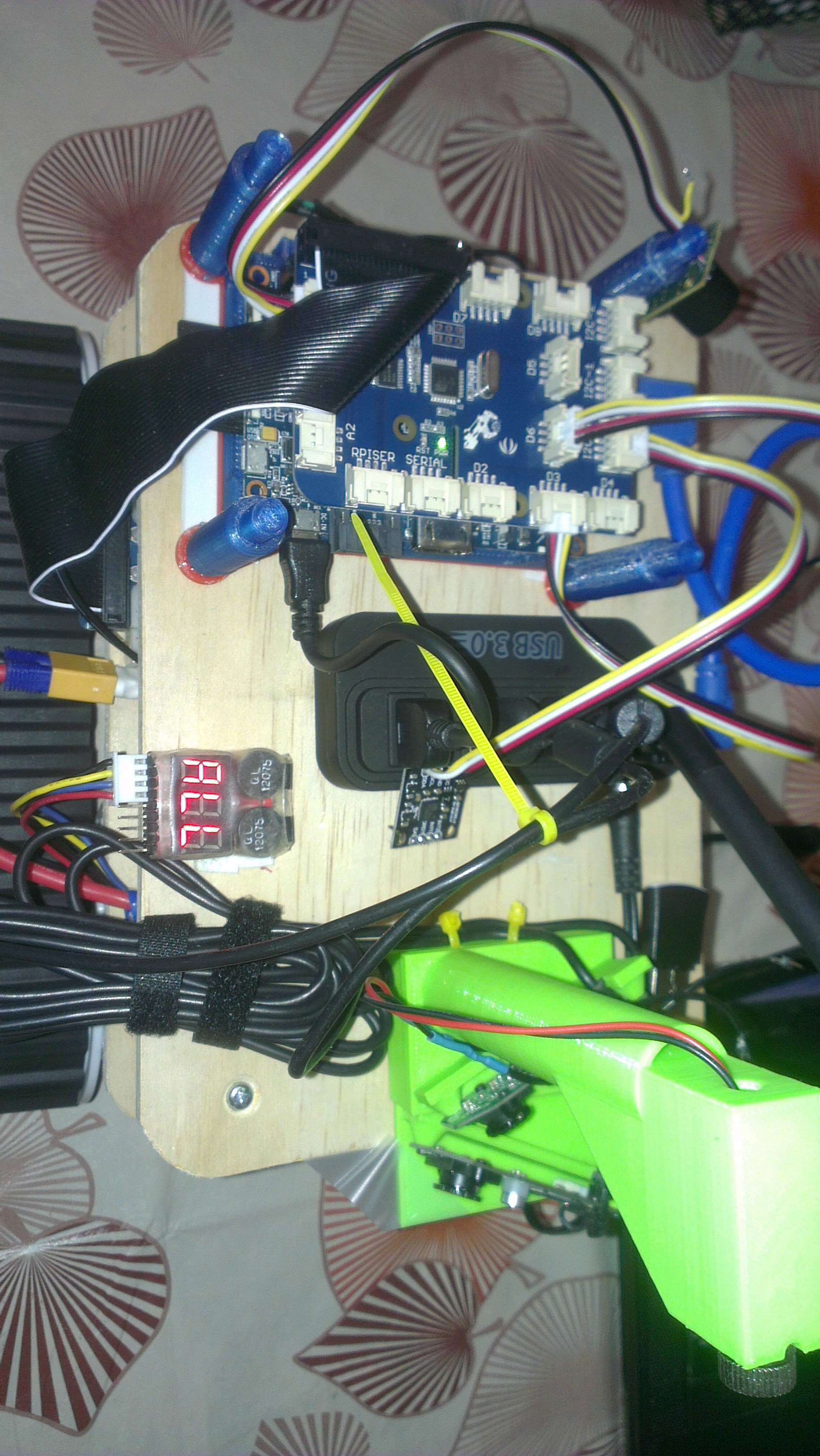
The power systems consisting of battery, 2 switch mode power supplies and an hbridge are on the lower layer. The Pi and sensors are on the upper layer separating them from the electromagnetic fields of the power systems. The compass is elevated on a pole for further isolation from magnetic fields which is particularly important for the compass.

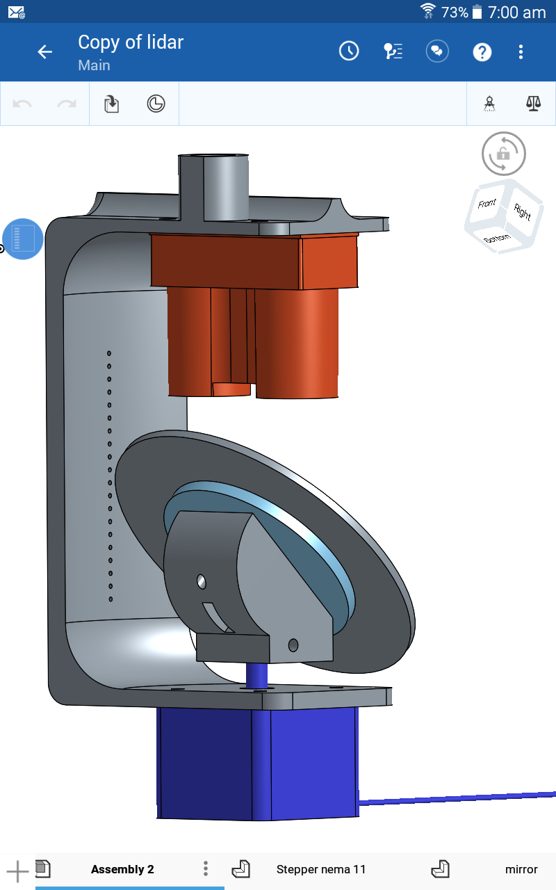
Laser range finding is achieved with a LidarLite mounted over a stepper motor rotating a mirror mounted at 45 degrees.

Although autonomous operation is the intent, a very basic user interface has been built to allow control of the bot for testing purposes. Simple operations such as setting the heading, forward & backward speed are implemented, as well some feed back on the current heading of the robot.

Next SLAM (Simultaneous Localisation and Mapping) will be tackled.

  • 1 × rover 5
  • 1 × adafruit i2c pwm board
  • 1 × dual hbridge
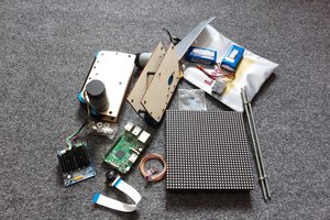
  • 1 × raspberry pi
  • 1 × i2c compass

View all 12 components

  • Evolution

    rlsutton104/08/2018 at 22:41 0 comments

    If you were interested in this project you should have a look at its successor Here

  • Platform Rebuild

    rlsutton101/31/2017 at 02:39 3 comments

    My continued work on a SLAM algorithm has lead me to remove the tracks from the platform and replace them with wheels in order to improve the quality of the odometry data. I was able to reconfigure the rover 5 platform, removing 2 wheels and pivoting their arms up and out if the way while moving the other two arms with wheels to the center of the bot. I also added a 3rd lazy wheel and moved as much weight as possible over it.

    I have also redesigned the scanning lidar assembly giving it an almost unobstructed 360 degree field of view, to achieve this also reguired increasing the height separation between the lidar and things like the wifi antenna and raspberry pi stack.

    I've removed the compass as it was practically useless, it's accuracy is greatly effected by surrounding metal objects - the fridge would throw it off by as much as 45 degrees when the fridges compressor is running.

    The other major change is around the general shape of the robot. Changing to round allows simply pivoting on the spot when near an obstacle, the original rectangualar shape had corners which protruded and would cause the robot to become stuck when turning at close quarters.

  • Dead reconning and particle filter

    rlsutton107/19/2016 at 12:34 0 comments

    After outputting delta heading to csv and graphing it I determined the maximun valid rate of change to be 25 degrees per second.

    I capped the output of the gyro to this rate which resulted in very accurate dead reconning data considering the ground slip.

    This lead to me bringing down the heading noise level of the partical filter, which brought to a head a problem which I had suspected for a while.

    The problem was the change in heading I was feeding to the particle filter was an absolute value... turning left was left and turning right was also left. But the partical filter with high noise settings was able to hide the erroneous input coming in to it.

    This really high lites how hard debugging non deterministic code such as a particle filter is.

    With this problem solved and the noise set nice and low the robot becomes much less vulnerable to becoming lost.

    I set the speed proportional to the standard deviation of the particles in the particle filter and as a result the bot is now able to make faster and more reliable runs.

  • New lidar mount

    rlsutton107/18/2016 at 22:49 0 comments

    I spent the last few weeks designing a new mount for my lidar which should give a 270 degree field of view. The ABS print is slightly warped and I am considering my options to fix it, the lidar mount top plane is misaligned by about 3 or 4 degrees.

    One option is to simply add a small plate with some shims or washers to correct this.

    I'm also considering baking the print in the PID controlled toaster oven for a few hours at 70c with a jig holding it at the correct angle or slightly over.

  • Switched to gyro

    rlsutton107/11/2016 at 22:54 0 comments

    Changing the dead reconning from using the tracks odometry to using a gyro for calculating the change in direction yielded a significant improvement.

    The raw telemetry and lidar scans now produce a reasonably reconisable map.

    The gryo however suffers continual drift. I've eliminated this when stationary by simply ignoring data from the gyro when the tracks are not turning.

    There are also occasional blips of sudden and large magetude change in heading coming ftom the gyro. I intend to try using the calculated change in heading from the tracks odometry to cap the gyro output. This should work as the original problem was that the odometry over estimated the amount of turn due to slip and the gyro only does this occasionally.

    I will also be looking at the code i am using to integrate the raw data from the gyro, as it currently has no time compensation and neither the os or java are realtime.

  • Tracked vehicle telemetry and a dodgy compass

    rlsutton107/04/2016 at 22:48 0 comments

    The particle filter was becoming lost when the robot performed a turn - this ultimately turned out to be a problem with the particle filter resampling interval, but it opened my eyes to the fact that tracked vehicles do not perform deterministic turns.

    Observation revealed that when one track was stopped and the other moving, the pivot point would not be around the center of the stationary track but rather around one of the ends of the stationary track leaving the dead reconnecting very wrong. The change in heading was off by almost 50%.

    I had previously stopped using the compass in the dead reconning process because of the presence of large magnetic fields like the fridge etc. The lsm303 compass also seems to crash regularly (suspect I should by a new one). One day I will install two compasses at opposite sides of the robot so that the presence of local magnetic fields can ge detected, as a local magnetic field will cause the two compasses to point in defferent directions.

    The plan now is to use a gyro to feed change in heading data to the particle filter.

  • Particle Filter and basic Navigation

    rlsutton105/01/2016 at 10:49 1 comment

    Earlier in the year I spent some time doing the free online course "Artificial Intelligence for Robots" at https://www.udacity.com/

    I've not yet implemented everything I've learnt from the course, but have found the time to implement a particle filter and some basic route planning.

    I found the noise setting for the particle filter to be very important, to little or to much noise an the robot will end up lost.

    You can see a run below, I've subsequently improved its speed and routing but the video shows working quite effectively.

  • Changed to Scanning Lidar Lite Setup

    rlsutton112/28/2015 at 11:39 0 comments

    I've replaced the Laser Line / web cam sensor system with a Lidar Lite mounted over a rotating Servo, more details to come later... Some video of it in action below

  • grovepi

    rlsutton105/18/2015 at 22:51 0 comments

    I decided to put a grovepi on the robot in order to clean up the bread board mess.

    Unfortunately the banana pi holds the grovepi reset pin low by default, but only took me a few hours to work that out.

    Because I was having issues which i was incorrectly blaming the banana pi for, I have currently switched back to the raspberry pi while I'm working through the issues with the javea code to talk to the grovepi.

    I was able to completely reove the dedicated pwm board from the build, and things look a lot cleaner now.

    It only took me 4 weekends to get everything working again.

  • Move to webcam based range finding & Banana PI

    rlsutton101/07/2015 at 22:31 0 comments

    See the picture of the bot with the 2 stripped down web cams on the front.

    I've moved to using a pair of Logitech c-270 web cams for range finding. I printed a custom mount to hold both webcams and a laser line. I stripped the webcams out of their cases as the cases made them difficult to mount. One cam faces 25 degrees left and the other 25 degrees right, giving a field of view of 100 degrees and both are tilted up so that the bottom of the image is just below horizontal.

    I've written my own code in java (see GitHub) to process the images and locate the laser line to calculate the ranges. I make n (30) vertical scans down the image looking for the laser line. Knowing that I am looking specifically for a laser line allows simplification of the problem for example; The line is never vertical, every point located on the line must have a neighboring point.

    I've also moved from the Raspberry PI to the Banana PI, allowing the image processing to take place on the robot at 5 frames a second for each web cam and still leave some spare clock cycles for other things. I've created a pull request for the Pi4j project for a small change to work with the I2C bus number that the Banana PI has, otherwise the Banana PI was a drop in replacement for the Raspberry PI.

    Work has started on SLAM from scratch, and a graphical mapping UI which runs on a laptop.

View all 16 project logs

Enjoy this project?

Share

Discussions

Derrick Bommarito wrote 03/13/2014 at 15:59 point
You'll most likely find that losing that many encoder ticks (all at once, periodically) is going to hose any hopes at navigation; not that tracked vehicles are great for odometry to begin with. One turn with some missed ticks and you're now way off your heading.

With that said you may want to look into writing a small C program to do the encoder counting and using some simple IPC (inter-process communication) to get the data from the C program to your java program. A look at this website, http://research.engineering.wustl.edu/~beardj/CtoJava.html , may get you started. Otherwise, as you stated, your next best step is to move the encoder counting to external hardware.

  Are you sure? yes | no

rlsutton1 wrote 03/13/2014 at 20:11 point
Thanks for that I had thought just yesterday that I should write some C for this task. Hopefully I'll write some C this weekend to get this job done.

As to navigation I'm not using the encoders for heading, I have a compass for that.

Ultimately when my Pixey (CMUcam5) turns up I intend to be doing laser range finding as my primary source of positional data.

  Are you sure? yes | no

Similar Projects

Does this project spark your interest?

Become a member to follow this project and never miss any updates