Carl Bugeja
-
Update
06/08/2018 at 22:35 • 1 commentA quick update on my PCB Motor prototype:
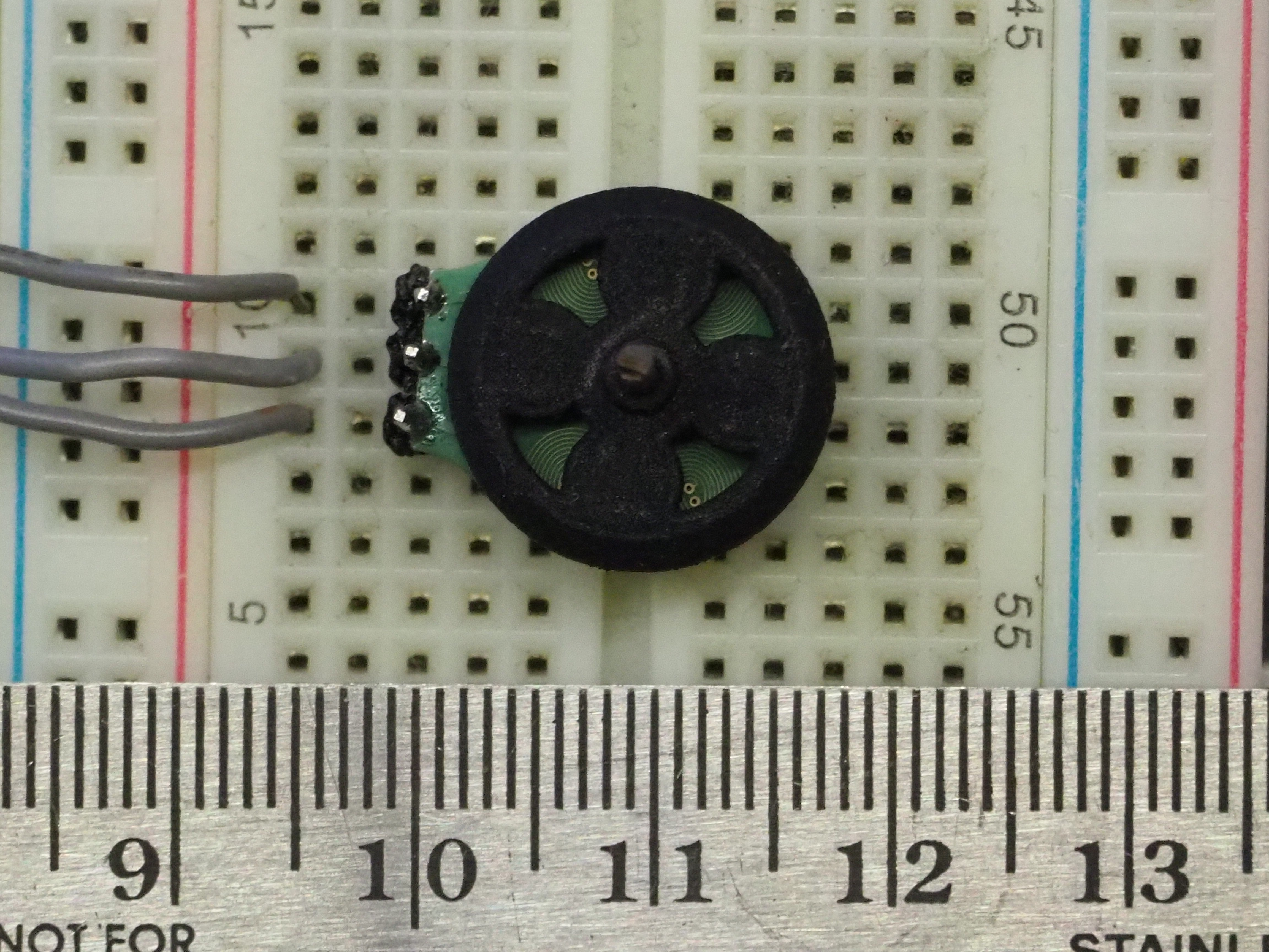
- Dimensions - 16x17x5mm (excluding the shaft)
- Weight - 1.6grams
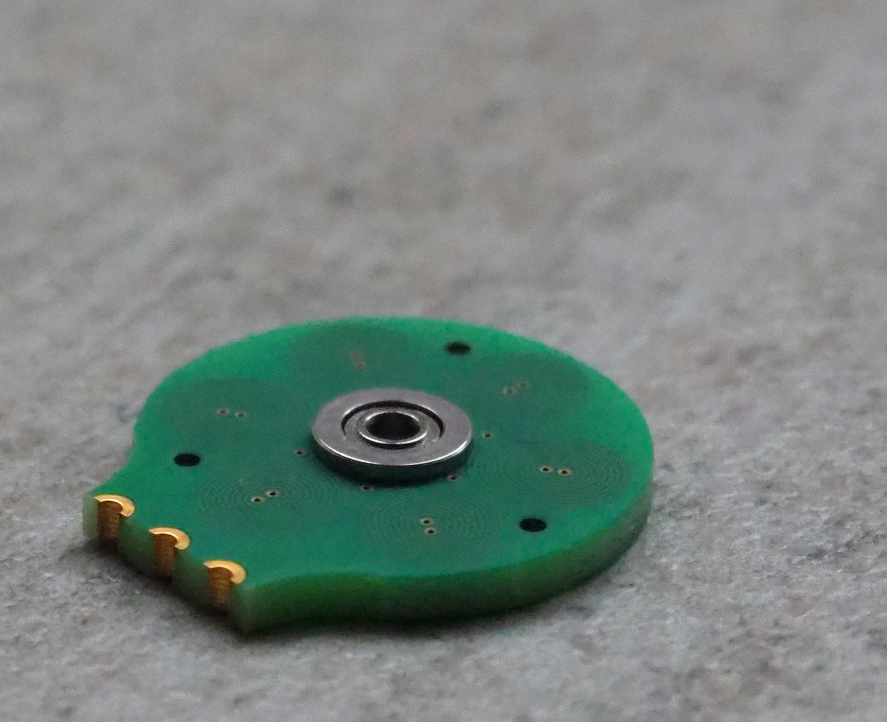
- PCB Stator - 6 Poles connected in a delta configuration, with 40 turns each with 4/4mil traces.
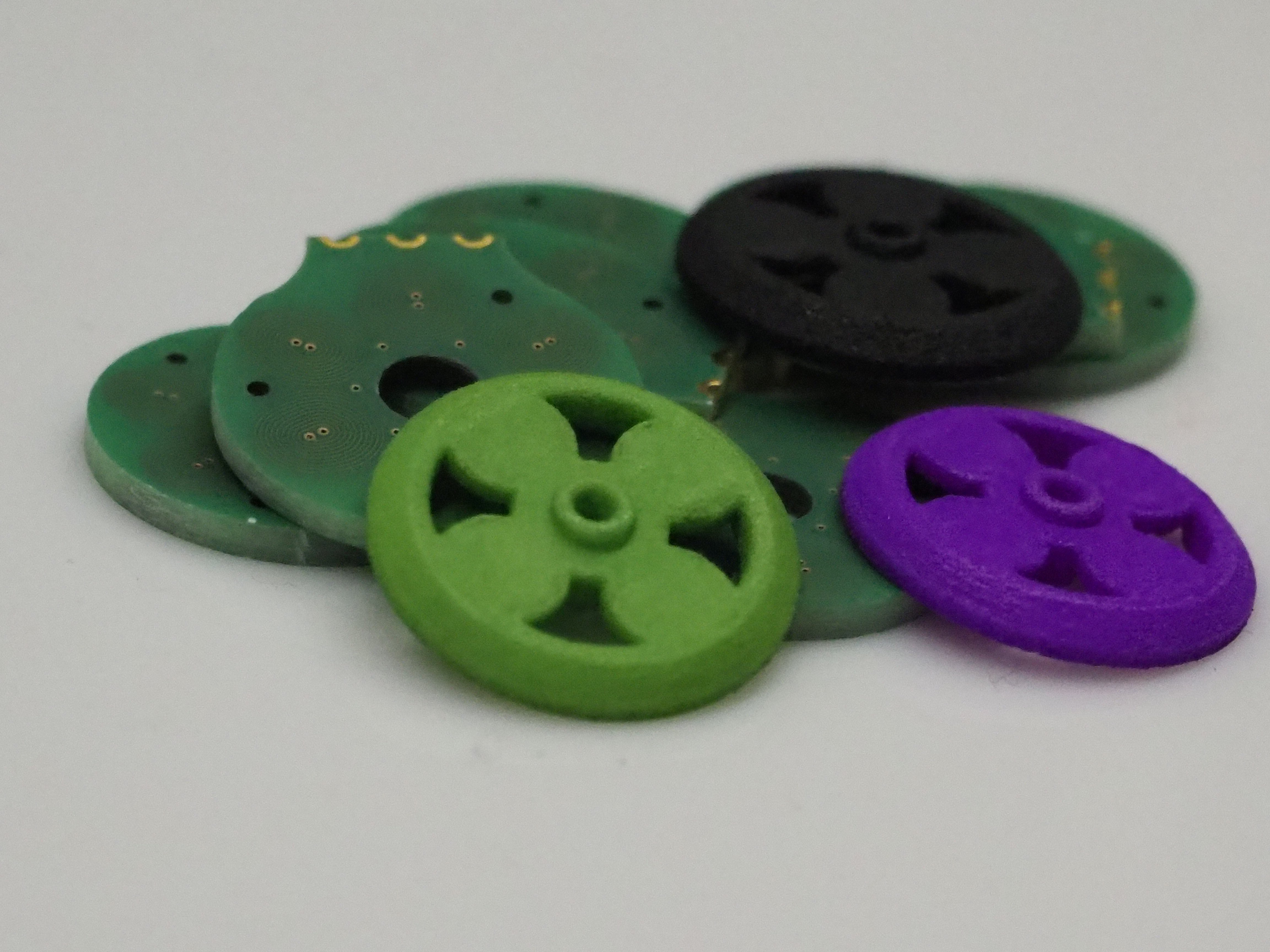
- 3D Printed Rotor - 4 Poles
- Bearings - Stainless Steel
- Phase Resistance - 19.3 ohms
- Power Rating - 1W
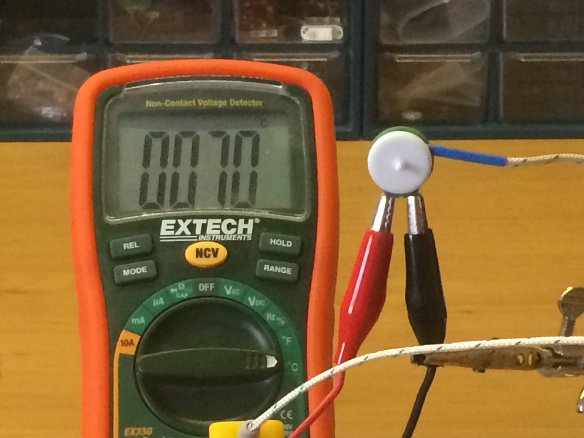
- Maximum Temperature - 70°C (at 5V)
- Maximum Torque - 0.9 g.cm
Improvements that I'm planning to test:
- Torque
- Temperature
- Increase the winding's magnetic field strength by reducing the PCB thickness
- Use ceramic instead of stainless steel bearings to reduce friction
- Experiment with different trace winding's clearance and thickness. Increasing it to 5/5mil from 4/4mil will reduce the pcb's cost at low volumes. However, this would also enlarge the motor's diameter to reach same parameter's of the 40turn 4/4mil coil.
-
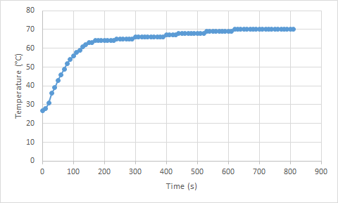
Thermal Testing
05/27/2018 at 21:21 • 0 commentsHow hot is my pcb motor getting? With a direct 5v supply on the windings it reached a maximum of 70°C after 13 minutes of continuous voltage.
How to improve this? For the next prototype I'm going to use more vias and a copper plane on all four layers to conduct heat on a larger area.
![]()
-
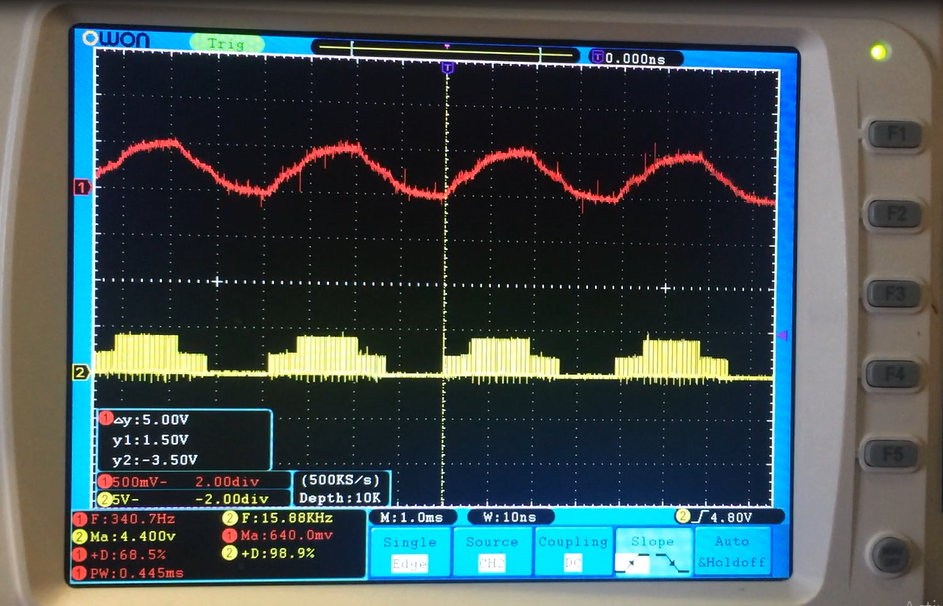
Closed-loop Control
03/27/2018 at 20:09 • 0 commentsMy plan for speed controlling the PCB Motor was to implement a sensorless back-emf speed controller, which works just like every other brushless ESC. It measures the time it takes to detect the zero-crossing point from the under-driven phase, and adjust the commutation waveforms according. However, during testing the back-emf generated in the windings of the PCB motor was a little weak.
Plan-B is to use a hall sensor to implement the closed loop speed controller. This will be a little more pricey but will also include positional sensing.
-
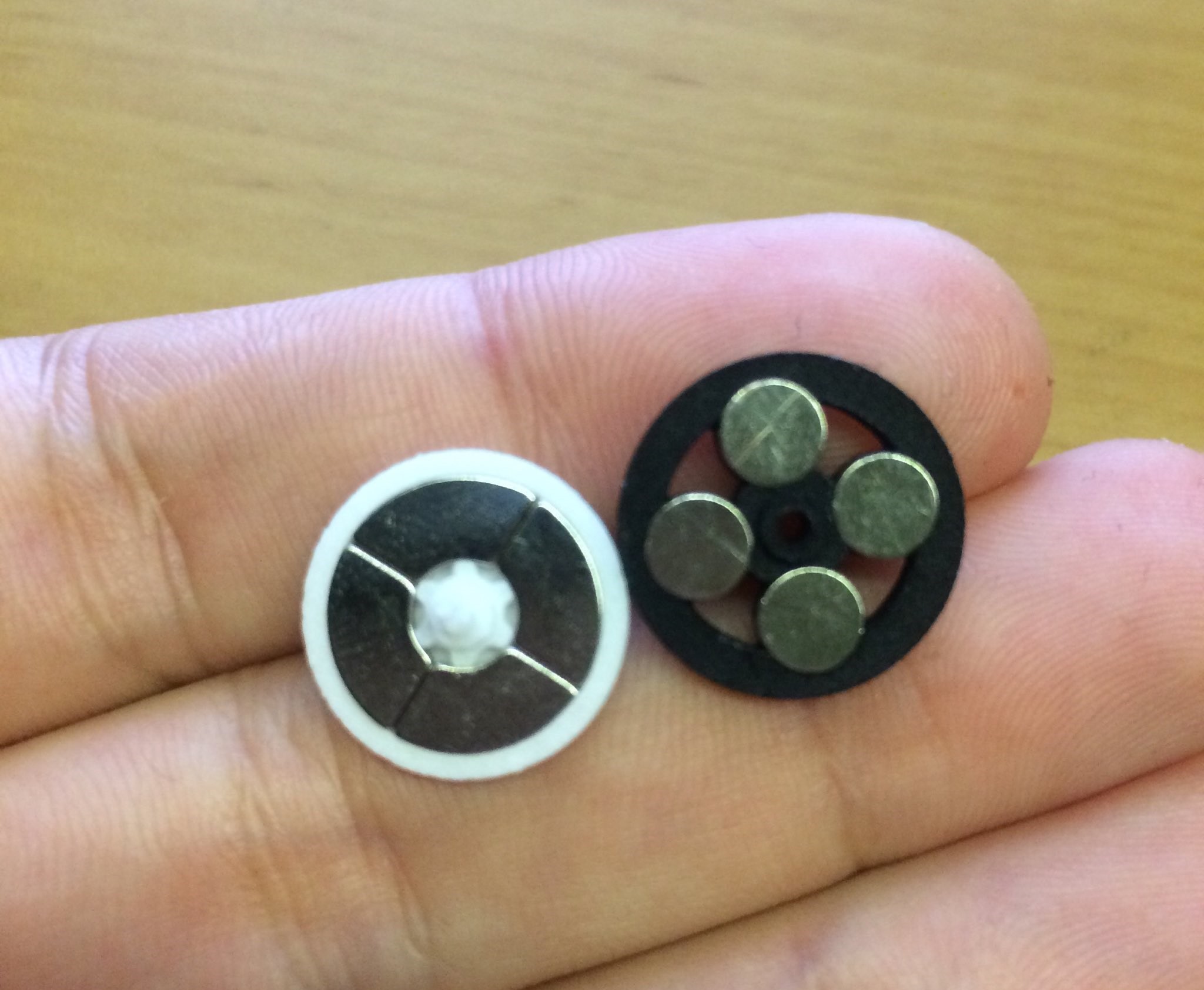
New Rotor
03/05/2018 at 00:33 • 1 commentThis is a new 3D printed rotor prototype i designed, with a snap-hook shaft and press-fit circular magnets!
I managed to use 4 circular magnets with the new rotor that makes the magnetic field more uniform across its whole area.
![]()
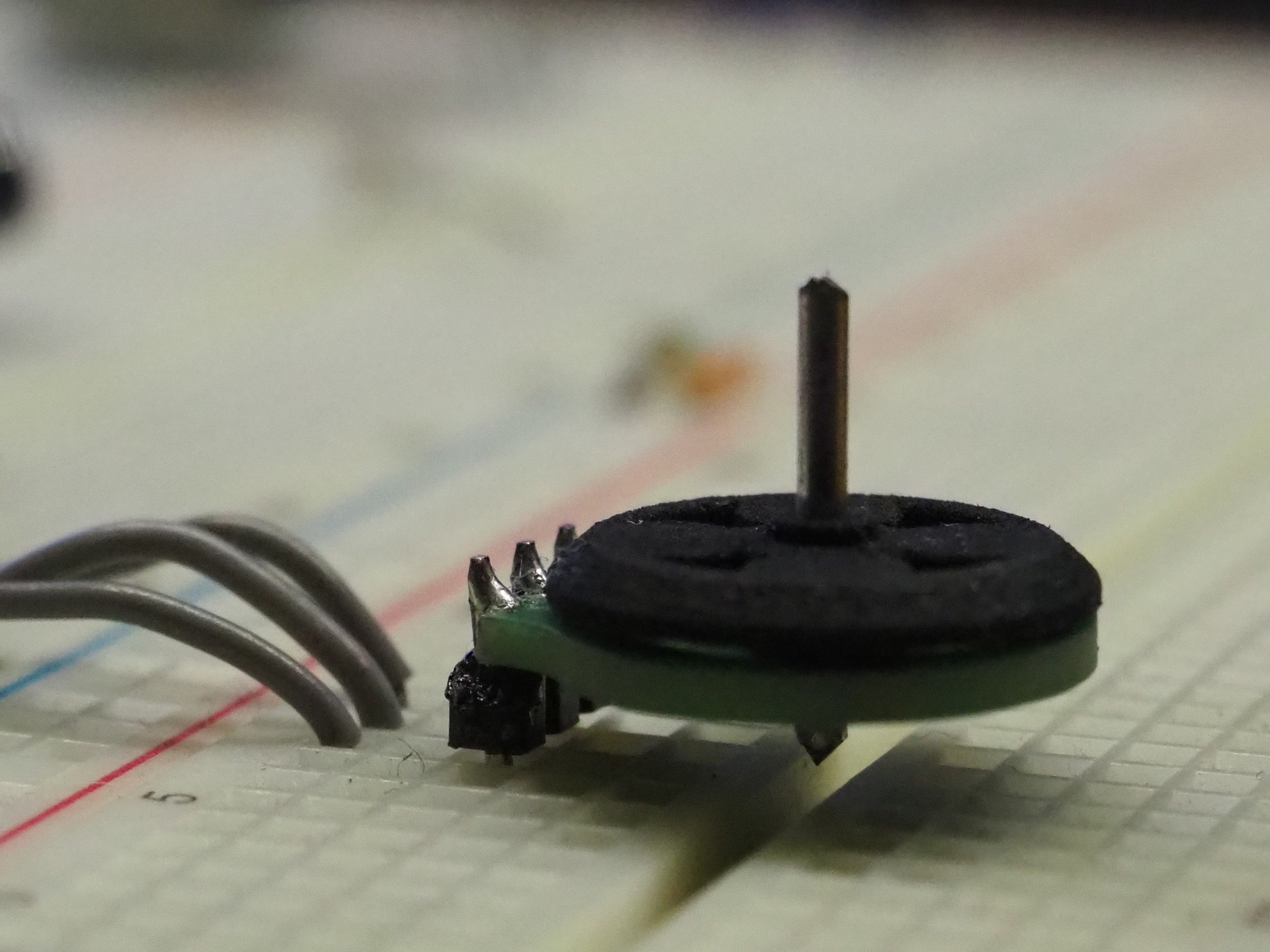
The metallic shaft was also eliminated. Instead it was made part of the 3D rotor model, At the end of this shaft are two snap-hooks that lock the rotor inside the bearing.
![]()
This feature makes this brushless motor more cheaper and easier to assemble. Its now just a three step process!
- Put the magnets in the rotor
- Put the bearing in the pcb
- Snap in the rotor onto the pcb
-
PCB Motor - Explained
02/25/2018 at 13:58 • 0 commentsThis video briefly describes how my brushless PCB motor works.
-
Open Source Files
02/07/2018 at 23:09 • 0 commentsThe gerber files and STL file for the first PCB-Motor prototype are now available for download.
If you don't have access to a 3d printter, you can purchase the rotor here: https://www.shapeways.com/product/GD48BQX8D/pcb-motor-4-pole-16mm-rotor?optionId=64748243&li=shop-inventory
![]()
-
How I design the PCB stator
01/27/2018 at 09:37 • 1 commentThis project started with me trying to design a small cheap drone. Dc brushed motors are typically used for micro-drone designs since they are much cheaper than brushless motors. But these motors were not compact enough for my application. So I started looking into ways to make a custom brushless motors which is smaller, cheaper and easier to manufacture.
A normal outrunner brushless motor is made from a stator, a rotor and a shaft that connects the two via a bearing. Its stator has windings around an iron core to rotate the magnets on the rotor. The high magnetic permeability of the iron core creates a strong magnetic field around each coil, which improves the motor's torque strength.
I had this idea of making the stator embeeded in the PCB itself. My only concern was that to make it small, it had to be core-less. I decided to try it out and see if it had enough strength to rotate a small propeller (spoilers - it did).

PCB stator vs ADH30S's stator I wanted the first prototype to have the best possible chance of working, while still being as small as possible. So I set the trace spacing and thickness to 0.1mm and the via's drill size to 0.15mm. Although these parameters would increase the manufacturing costs of the PCB, it was the safest starting point for my PCB motor design.
I decided to make my motor have a 4-layer 6-pole stator, to have as many windings as possible. The star type stator configuration was used to limit the phase voltage, hence limiting the overall power of the motor (more power = more heating in stator coils).

Gerber Files of the 4-layer Stator There is alot more of experimentation and testing that I need to do before trying to integrate it with a drone. I want to find the best "turns-to-size" ratio and how does that effect the motor's torque. I would also like to test the delta configuration and a PCB-motor with a 9-pole stator.
-
Propeller Test!
01/24/2018 at 20:34 • 0 commentsTesting my brushless PCB-Motor with RX2535W propeller.
-
Dimensions
01/23/2018 at 18:46 • 0 commentsThe first PCB Motor prototype measures 16x17x5mm (excluding the shaft) and weighs 1.5 grams.
![]()
![]()
-
Solid-State Stator
01/22/2018 at 22:36 • 0 commentsThe first PCB prototype has a 6-coil star-type stator, each having around 40 turns.
![]()