5.
Upload .ino-files: youtube
4.
Board Wiring: youtube + Arduino file: Knight Rider Test
3.
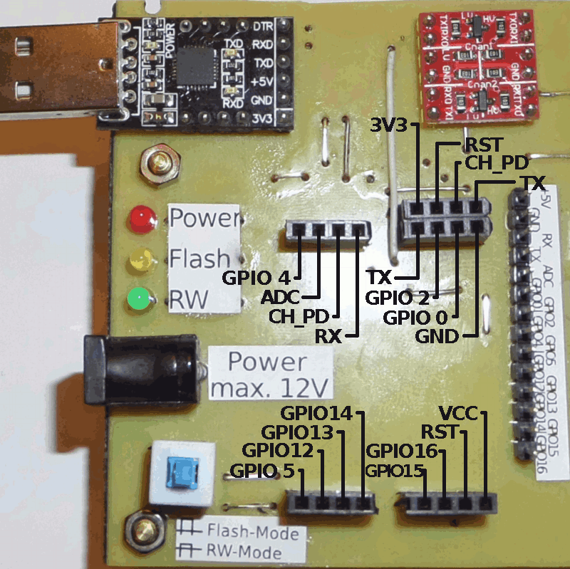
Shield Pinlayout: youtube
2.
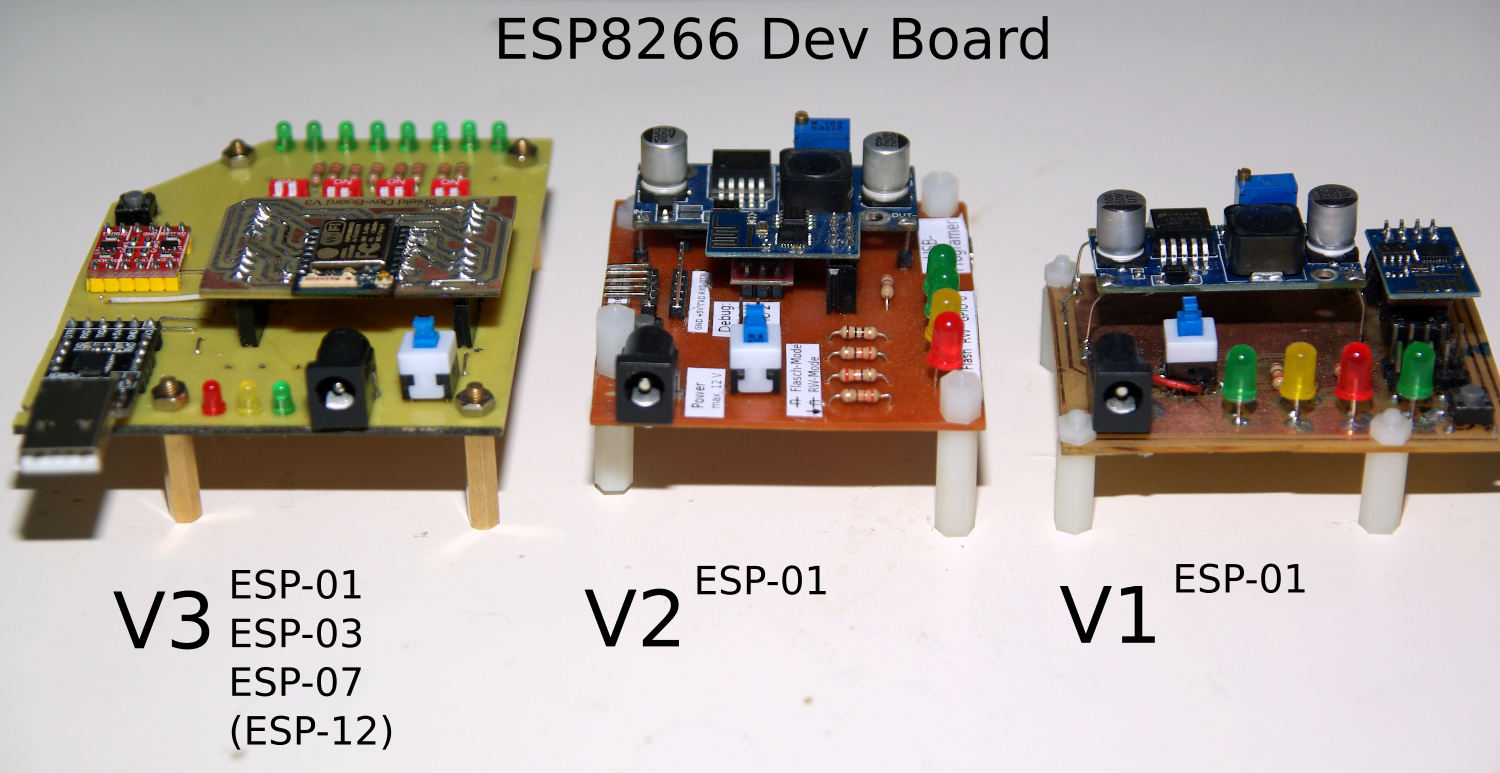
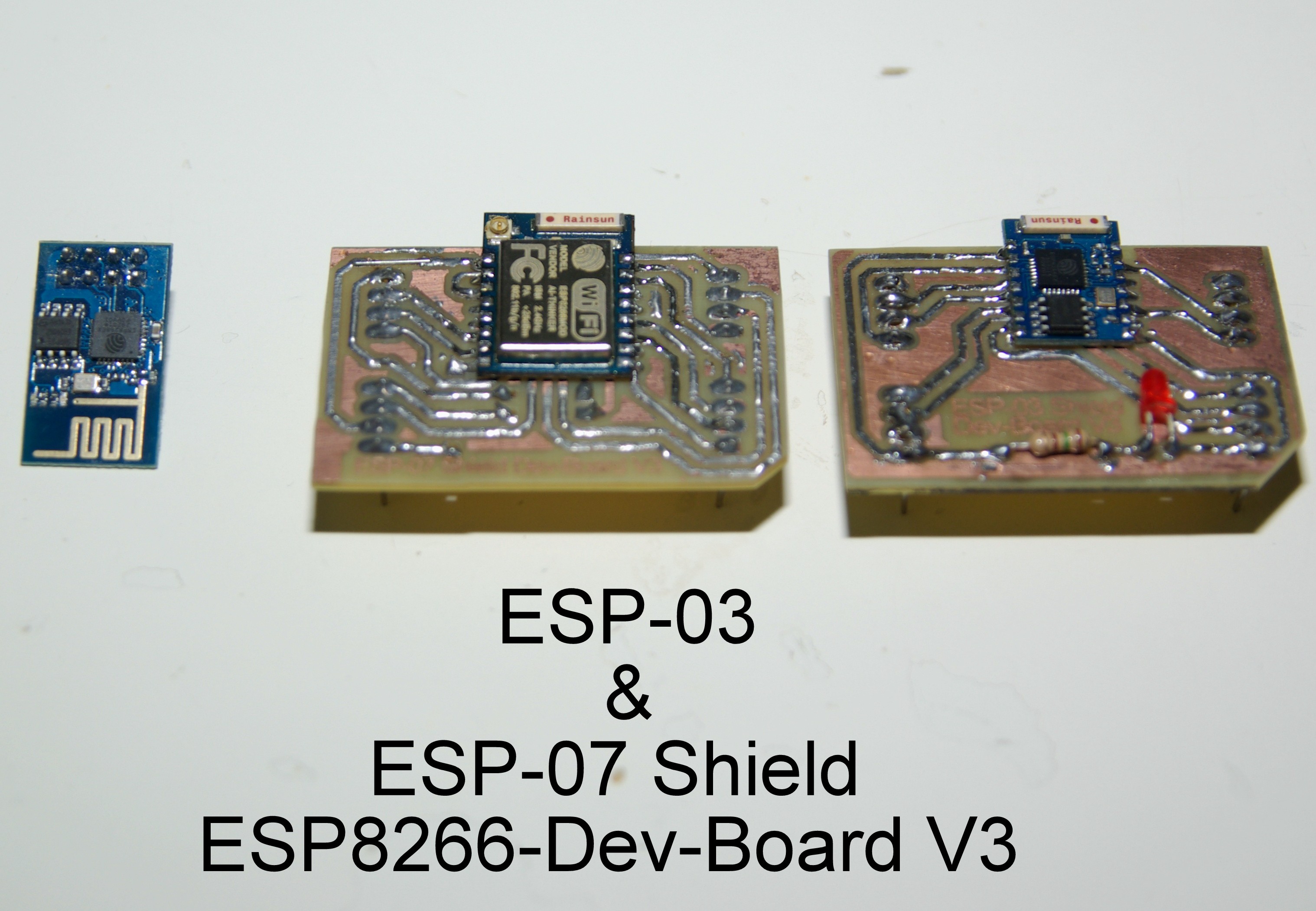
Dev Board V3 ready.
1.
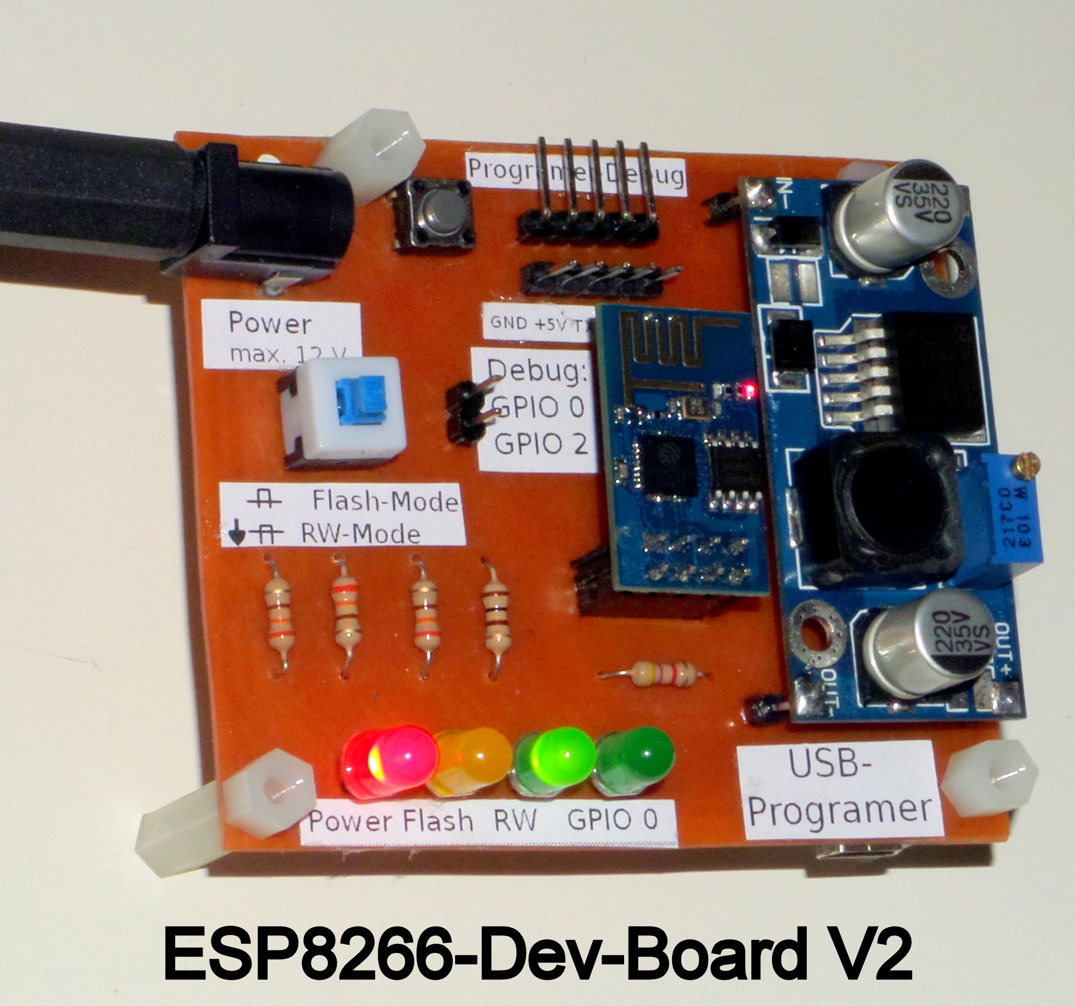
Version 2 is ready.
Eagle files with parts for downloading, look :
Note:
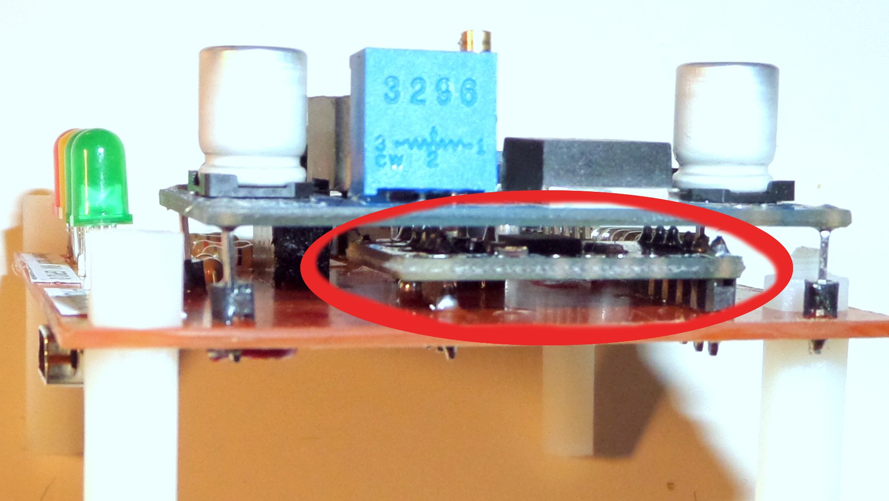
The USB-TO-TTL Programer is unter the LM2596S. See picture.
I dissemble a CP2102 converter and solder it on PBC.
The USB connerctors from CP2102 are solder togethereith copper survace and connects an SMD Mini USB female connector ( in picure on the left).
This is not nessesary, but easy to get an fast development with ESP8266.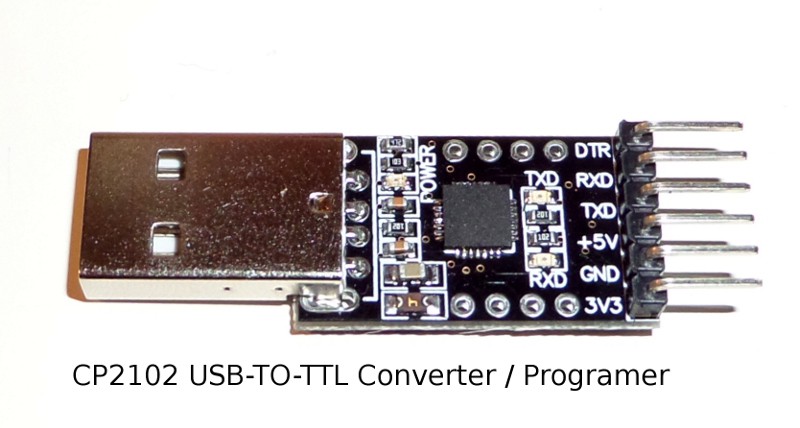
Think the PBC will get much more smaller without programer on board.
The third version will come in April 2015.
 Chris Wagner



 Sander van de Bor
 Ben Lim
 Bruce Land
Meinen Glückwunsch zu dieser Idee. Da ich von diesem Projekt begeistert war, habe ich mal versucht es nachzubauen. Leider funktioniert es bei mir nicht. Problem ist folgendes: Ich habe aus Eagle heraus das Layout für das DEV Board V3 gespiegelt gedruckt. Auf eine Platine übertragen und geätzt, soweit so gut. Nun zum ersten Problem: Beim Levelshifter sollen 5 V vom CP auf der Seite HV reingehen und bei LV sollen 3V raus kommen. ( Wenn ich das richtig verstanden habe) Bei mir kommen da aber keine 3 V raus sonder nichts, somit ist natürlich die ganze Stromversorgung nicht gegeben. Bei dem von mir hier vorliegenden Levelshifter kann ich auf der LV Seite 5 Volt rein geben und auf der HV Seite kommen dann 2,5V raus. Also habe ich mir gedacht ich spiegele das Layout mal nicht und habe eine neue Platine geätzt. Nun passt das zwar und beim PIN wo der ESP01 z.B. eingesteckt wird, kommen auch 3,3 Volt an, jedoch geht der ESP nicht an. Also leider weis ich hier nicht weiter, was oder wo kann der Fehler sein? Auf deinem Schaltplan ist auch der LM2506S eingezeichnet, denke das dieser aber für eine andere Versionen des Boards ist.
Schade das es nicht geht, vielleicht hast du aber auch einen Tipp für mich wo mein Fehler evtl. ist. Was ich auch nicht verstehe ist, was versorgt eigentlich der Power Conector, außer die LEDS?
Mit google übersetzt in der Hoffnung du kannst deutsch :-)
With Google translated hoping you can German :-)
Congratulations to this idea. I was excited about this project, I once tried to recreate. Unfortunately it does not work with me. Problem is this: I have printed out from Eagle layout of the Development Board V3 mirrored. Applied to a board and etched, so far so good. Now for the first problem: When level shifter to 5V by the CP to go in on the HV side and LV are at 3V come out. (If I have understood correctly) with me to come there but not 3 V out special nothing, therefore all power is of course not given. In the level shifter present from me here I can on the LV side give 5 volts in and on the HV side come out then 2.5V. So I thought I did not reflect the layout of times and have etched a new board. Now that matches indeed and the PIN where the ESP01 example is inserted, and 3.3 volts to come, but the ESP does not turn on. So unfortunately I know of no further, what or where can be the error? On your circuit diagram and the LM2506S is located, but think that this for an other versions of the board is..
Too bad that does not work there, maybe you have but also nich a tip for me where my mistake is possibly. What I do not understand what is actually supplied the Power Conector except the LEDS?