-
Progress
09/03/2015 at 01:10 • 0 commentsI have been very busy working on this project since the last update, and I think I have something worthwhile to show now. During that time I have gotten bluetooth to work, rebuilt the display module, and done a ton of programming. I guess I will get started with explaining bluetooth first.
I ordered a new Raspberry Pi A+ to use for this project. It was needed because of its smaller and improved form-factor, and because of the many new GPIO pins it exposes. The latter is very important. In order to get audio to the FM transmitter, I can either run a short cable from the pi's audio output to the transmitter, or try to get audio out the GPIO header. Going the cable route takes up more space, increases complexity (another cable), and increases price. After doing a bit of research, I discovered that you can redirect the GPIO pins that the PI uses for audio to other select pins by messing with the Device Tree. However, the old Raspberry Pi B I have only exposes one of those valid pins, leaving me with only mono audio. Fortunately, the Raspberry Pis with the revised pin header exposes both pins needed for stereo audio.
With that out of the way, my next task was getting Bluetooth working. Only attempt this is you enjoy being in pain, and dreaming about bluetooth hell (which is a real place). Many guides for making it work exist, and while they worked, the results were not up to my standards. I wanted better sound quality, less latency, and better automation. I don't want to have to get my phone out and connect it to the Pi whenever I get in my car, or reconnect it if it disconnects by itself for whatever reason. What kind of manual loser do you take me for? So now begins the process of changing settings until results change/improve, image the sd card, screw it up somehow, reimage the sd card, find that something stopped working for no reason, start over, and repeat until you start screaming. After I have all but given up on decent quality automatic bluetooth, I find that the versions of bluez and pulseaudio provided by apt-get are severely out of date and missing many features that I need. Soon after, I find this forum thread and follow its instructions as a last-ditch attempt to make it work. It worked perfectly. Not longer after, I get an auto connection script going that forces the phone to connect whenever it's in range.
With that problem solved, my next task was rebuilding the display module. I decided to go with one of the 14 pin ATTinys as the primary microcontroller for the display module, either an ATTiny84 or 44. It's small, cheap, and easy to work with. I got it to handle button inputs, led brightness control, light sensor input, LCD control, and communicate with the Pi. However, it was not originally going to do all of that. Since the LCD can be controlled over i2c, I figured I would be able to make the Pi control it directly, and turn the ATTiny into an i2c slave. Of course it's never that easy. The LCD would refuse to talk to the Pi if it was alone, and would try to take the QN8027 down with it if it was connected at the same time. My makeshift logic analyzer has shown that it was trying to respond to the Pi's requests, but I could not determine why it was not working. After more screaming and attempts to make it work, I scrapped that idea and gave the LCD control job to the ATTiny instead. It works there somehow, so I won't complain. I am left with using serial for bidirectional communication between the Pi and the display module. And like always, there was a problem with that. The only small bidirectional serial library for the ATTiny which didn't require a crystal that I could find, was more or less broken. After some more sacrifices to satan, I found a fork of it which did work, so that's nice.
Eventually I somehow managed to get the whole program size down to less than 4096 bytes, allowing me to use the cheaper ATTiny44. I was able to accomplish that by stripping down the already stripped down serial library, making the Pi handle everything LCD related (except for very low level stuff), and enter the scary world that is Port Manipulation. It's no where near as pretty as using digitalWrite or analogRead, but it uses significantly less space. The display module is essentially a glorified GPIO expander now, but it works.
Next I had to integrate the display module with the pi, which means writing all the code for the Pi side. This was mostly straightforward, even though I did have to relearn Python. The video below shows a small part of what I have accomplished so far. There is no music playing because I did not take the time to set up my radio for some reason.
My next tasks include programming the rest of the code on the Pi, adding OBD2 functionality, finishing up the power supply, testing, and PCB design.
-
FM TX works
08/12/2015 at 00:46 • 4 commentsThis is a small proof of concept showing that I got the Pi to play music through the QN8027. The quality is not the greatest, but that's likely because of the cheap test radio I am using. I am able to adjust transmission frequency, and all that stuff.
My next task is to work on the display module while I wait for parts to arrive in the mail in the next few days. Once I recieve those, I can finish up the power supply and start implementing bluetooth.
-
Another change of plans
08/09/2015 at 05:23 • 0 commentsI have taken a break from this project for personal reasons, but I am finally getting around to bringing it back from the dead. During that break, I have taken some time to think about this project. I have realized that I can replace most of the current system with a Raspberry Pi A+. I decided to go with this new method for a few reasons:
- Tons of community support, less going through obscure Chinese forums trying to find specific datasheets
- Capable of handling more than just bluetooth
- $20
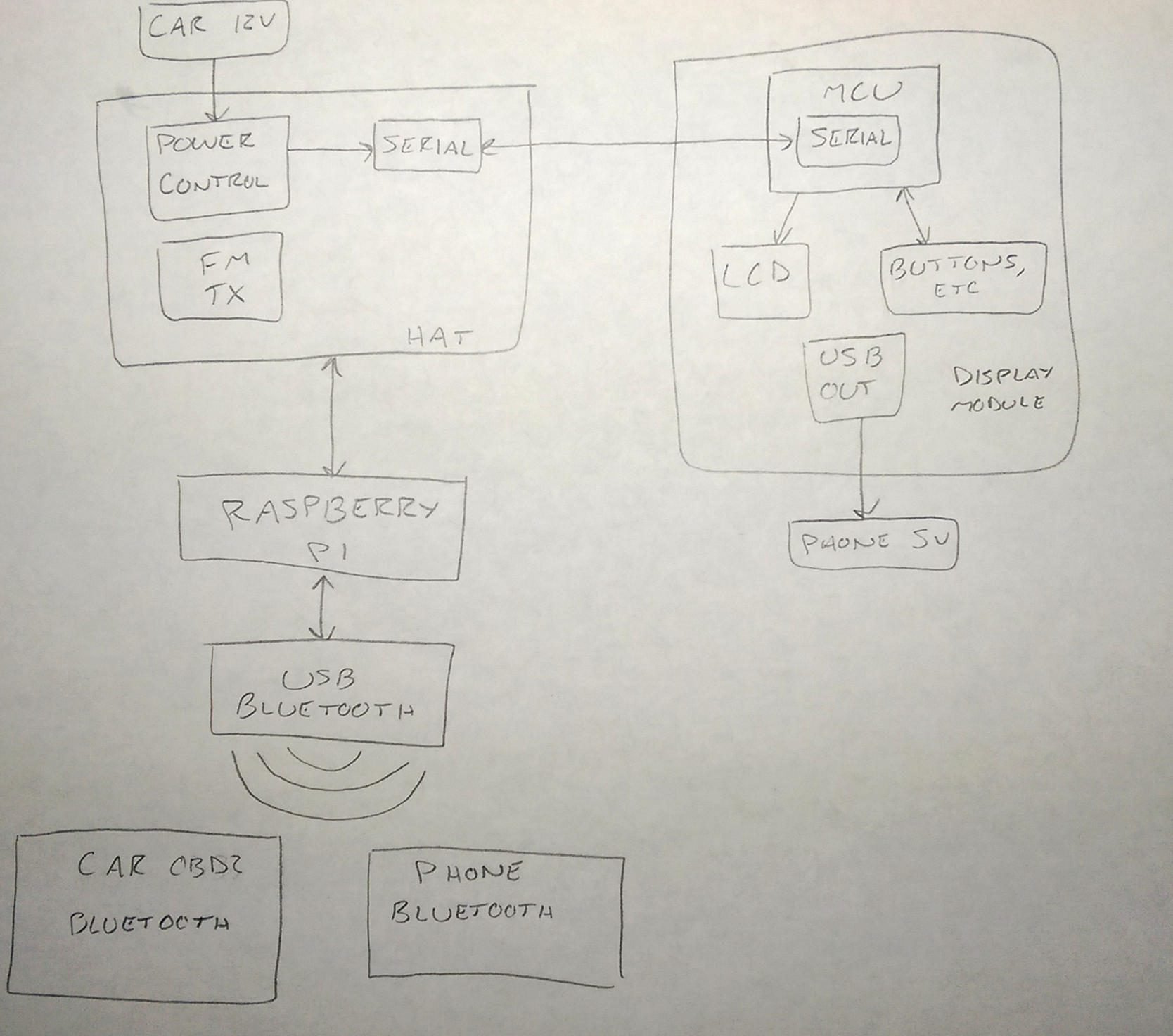
Bluetooth connectivity will be made possible with your average USB bluetooth 4.0 adaptor, using the CSR8610 SOC. The Pi will handle music streaming, control, and song data processing from the phone. The Pi should also be able to get data from my bluetooth OBD2 scanner, and do things with that. It will transmit the music over FM radio to the car using either PiFM, or more likely, the QN8027. The power supply/controller, fm transmitter, and other related devices will be located on a custom Pi HAT or something. For some reason I never posted how I found out about the QN8027 here (except on twitter), so I guess I will do that now.
Back in February I decided to take a look at the inside of my current FM transmitter to see how it worked, and to find out what it used to transmit FM radio. It was filled with vague and unmarked ICs. Fortunately, after some guessing and searching, I ended up with the QN8027.
According to this datasheet, the QN8027 is an FM audio transmitter. It can be controlled over I2C, supports RDS, and comes in a package that isn't impossible to hand solder. I found a few suppliers on aliexpress that sell them, so I quickly bought a few for testing. At first I tried deadbug soldering it, since I had no msop10 breakouts on hand. Don't do that if you value your sanity, and want something that doesn't end up breaking soon after. I ended up buying some breakouts. I will be honest, I have almost no idea what I am doing when it comes to RF witchcraft. Somehow though, I managed to make it work.
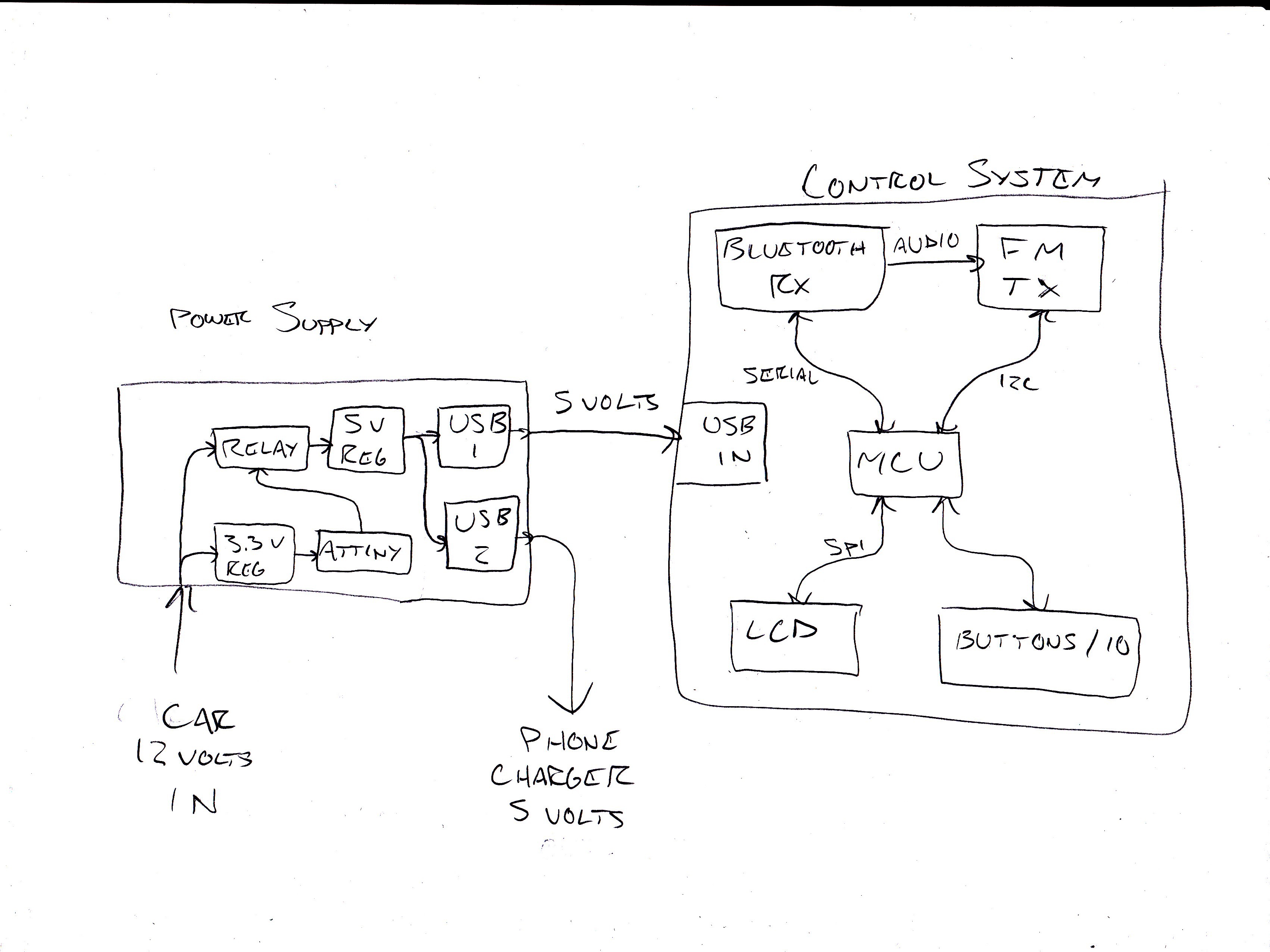
Anyways, music playback control and song data display will be handled by the "display module". This device will communicate to the Pi over serial through a USB cable, but USB itself will not actually be used. I am using USB because I don't want a long strand of dangling wires just leading from the Pi up to the display module, or some weird proprietary cable. The display module will have a USB output for charging the phone, though. Because of the reduced workload and IO requirements, I could probably get away with using a lower power/cheaper MCU for the display module.
Perhaps a block diagram will help explain things better:
![]()
-
Small status update
03/18/2015 at 16:23 • 0 commentsI have decided to rename this project to "carbt_v1", to keep in line with my other project names. Little by little, parts are starting to come in, and progress is being made. Prototyping and programming has began, and you can find my code repository here.
-
Change of plans
03/10/2015 at 19:35 • 0 commentsAfter some more thinking and research, I have decided to modify the project again.
I recently came upon the realization that using the large TFT LCD described in a previous post would introduce some problems. A larger and more complex LCD like that requires a larger and more complex PCB to support it. This will increase the cost and time necessary to design/build it. Since it is a "higher" resolution graphic LCD, the program complexity and overhead will also increase. For a project like this, graphics would be nice, but are not necessary. I did some more searching and found this nicely sized character LCD, very similar to your standard 16x2 char HD44780 LCDs.
As for what is going to be displayed on the LCD, I have decided to implement a menu system. For example, one could choose from FM frequency control, music control, settings, and likely more. Because of the reduced program requirements, I could easily get away with using an Atmega32u4 or Atmega328 as the main microcontroller. However, I would still like to try the LPC11U35FHI33 first, since it is a little cheaper.
I have also decided to do away with the separate power supply box, and integrate the power control circuit into the main device instead. This will reduce the overall system complexity, and also potentially reduce costs. I am planning on implementing the ability to enable/disable the voltage sensing capability, to allow for use on cars that don't have the problem mine does.
![]()
-
Power Supply Complete
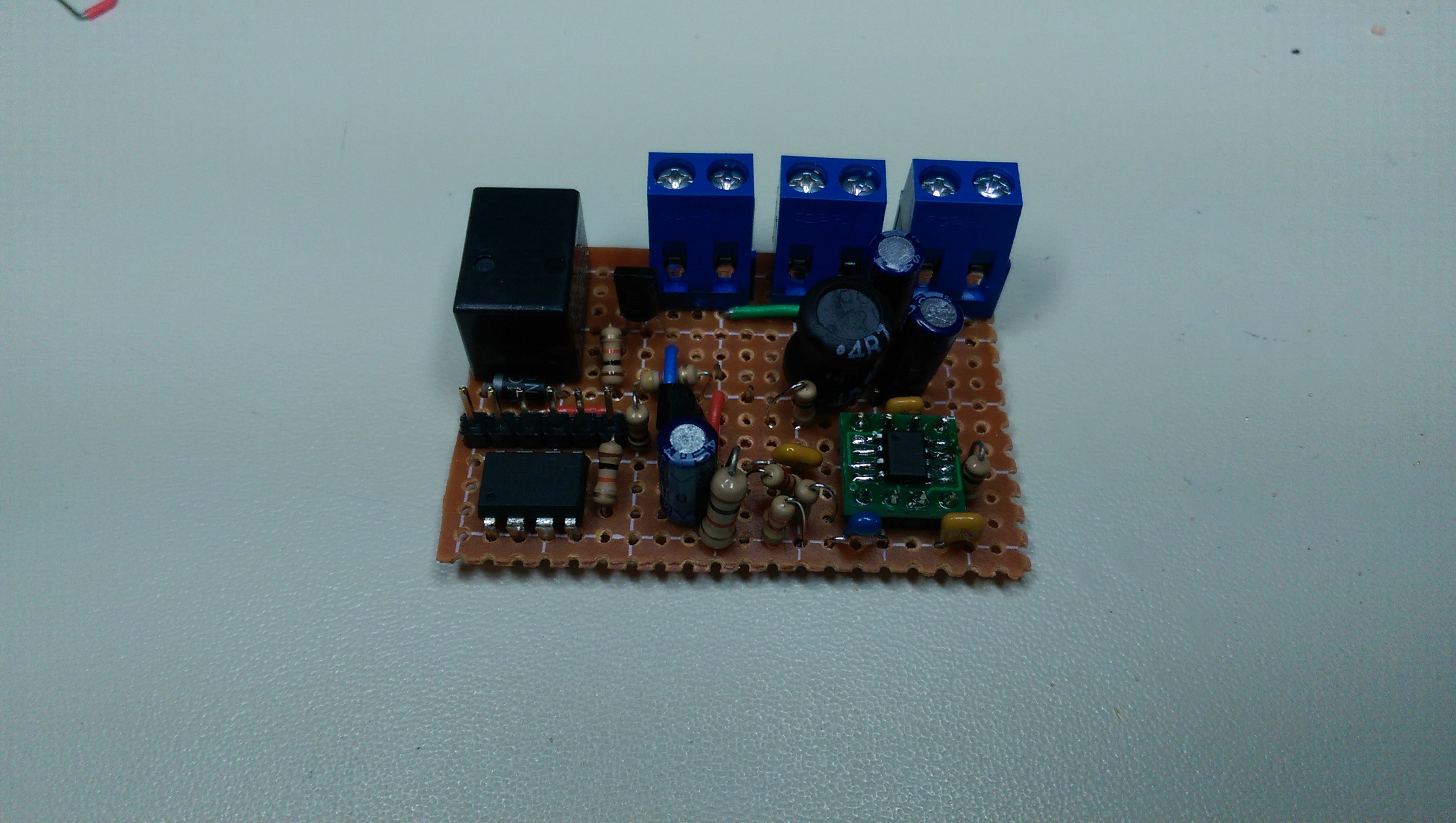
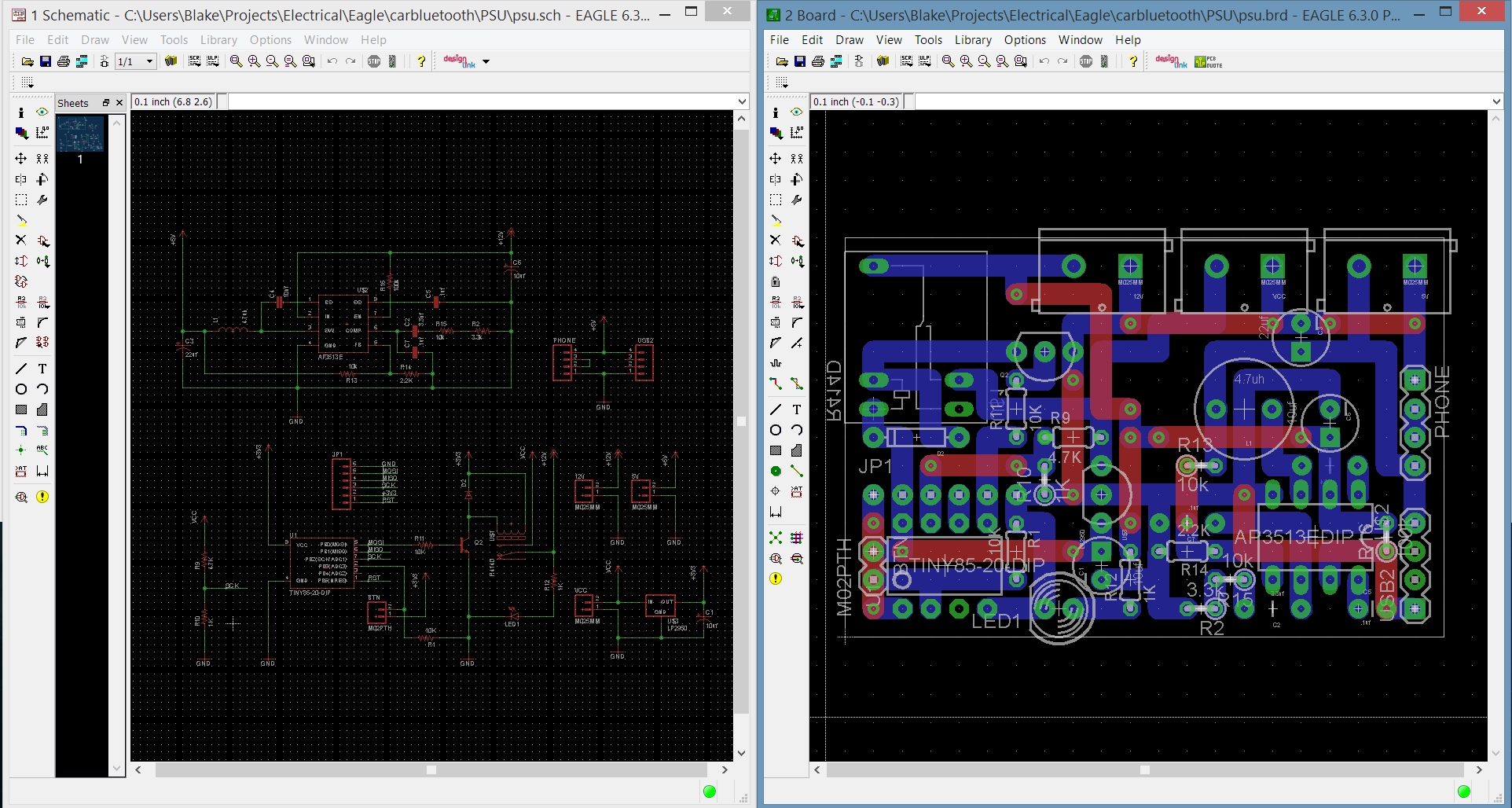
03/06/2015 at 01:48 • 0 commentsSorry for the lack of updates, I have been busy with other things and working on the power supply. During that time I have added a buck converter to the circuit for USB, and soldered it all onto a piece of perfboard designed in Eagle.
![]()
![]()
While it all works, it can still be improved. I soon realized that I did not need to break out all 8 USB pins (2x4), when only two were necessary (power and ground). There was also an issue with the placement of some components on the board blocking other parts. I did not take into consideration that the parts sticking out of the enclosure (button, power input, etc) would also take up additional space inside of the case. I had to re-cut a few holes as a result, and then cover it all with white paper (???????????). I also hot glued the USB ports to the cover, which caused the "springs" in each port port to become stuck. This increased the amount force necessary to plug/unplug USB cables from the power supply, enough to worry about pulling the ports out. Fortunately, nothing has broken yet.
![]()
But after much testing and tweaking the code, I think I can finally say it is more or less ready for use. It isn't exactly pretty, but everything works as intended and should be decently protected in its case. It turns on/off when the car does, charges my phone at 1 amp, and can be overridden when the car is off. The button I used is kind of lame, but I don't want to buy a better one if I don't have to.
As for the next part of this project, I am currently waiting for parts I ordered (almost a month ago) from China to arrive. I forgot about how the Chinese New Year tends to make everything there stop for a few weeks. I will be able to continue this project as I receive more parts to experiment with (which are finally starting to come in), and adjust plans accordingly.
-
Future Plans
02/04/2015 at 17:26 • 0 commentsAs I was working on the power supply, I began to think about what I wanted from the "control system".
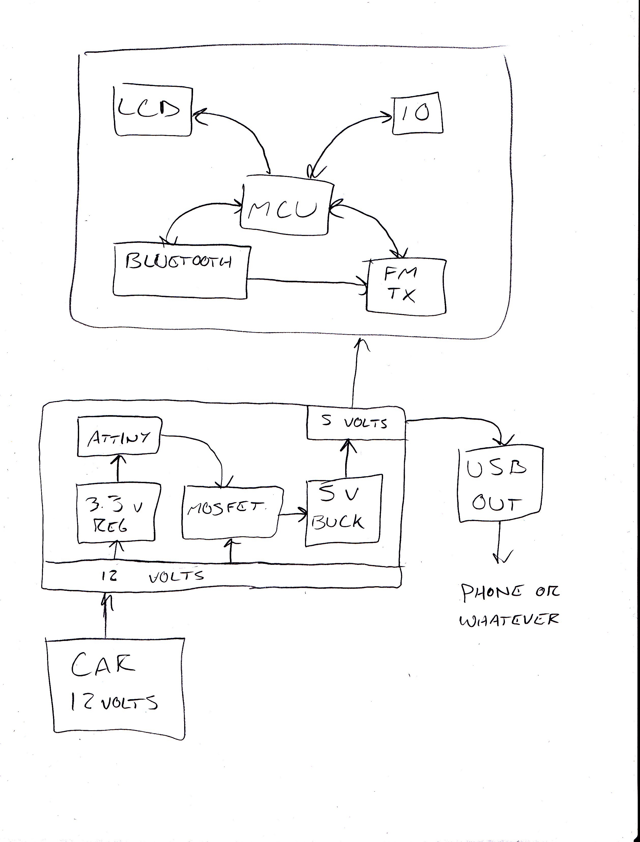
My initial plan was to stick the power supply board, my current fm transmitter, and bluetooth receiver into a box, with some control buttons leading out of it. This would have worked well enough, is easy to design, and is cheap. However, this isn't exactly the best solution for a number of reasons. I would have to sacrifice and waste unnecessary space with my "stock" parts, which also carry some issues. The fm transmitter has this "idle" feature, where it turns off if there is no audio being played. There are some situations where I need navigation audio played over the stereo, but with no background music. The fm transmitter controller will also need to be set out somewhere to control the transmission frequency, using up more space. The bluetooth receiver does what it needs to well, but has slight audio interference issues.
I could 'simplify' the system by integrating both the bluetooth audio receiver and fm transmitter into the control system. This would leave the power supply portion to be only that, a power supply. This also means I would need to find the parts used in the fm transmitter and bluetooth receiver, and incorporate them into the control system. The bluetooth receiver uses your standard OVC3860, and there are nice and cheap little breakouts for them on ebay. The FM transmitter was a pain to identify (vague, unmarked ics), but eventually I found that it uses the QN8027, a nice I2C controlled fm transmitter deal. The only "nice" place I can find it for sale is on aliexpress, and that's still a bit of a jump from what I'm used to.
I plan on having this all connect to an LPC11U35FHI33 ARM microcontroller, which controls this LCD. This is a large (and a little more expensive) jump from my initial plans, but it's nothing I'm not already used to. I also want to get into selling things on Tindie, so this could be a good start.
The following picture should hopefully describe what I want to accomplish:
![]()
TLDR: Feature creep
-
Power Supply
02/03/2015 at 19:49 • 0 commentsThis project needs a power supply. Since this is all going in my car, I'm going to use your standard 12 volt cigarette lighter as a power source. However, it is always powered, and I don't want the devices connected to it to drain the battery when the car is off. Since I also don't want to tap into my car's ignition relay, I'm going to detect engine activity by monitoring voltage changes. While the car is off, the cigarette lighter will measure about 12.3 volts. When the car is running, the voltage will be about 14.6. I can detect this voltage change with an Attiny85, which will control a relay that controls power to the connected devices. I could have not used the Attiny, but I like the flexibility and ease of use it provides.
I also want to be able to use the system while the car is not running, but I cannot reliably detect when the car is set to ACC. To get around this, I have added a button that can be used to enable the power supply for 10 minutes at a time. I could have used a simple toggle switch, but I am forgetful a piece of trash who has managed to lock their keys in their car multiple times. (always carry a spare in your wallet)
This video shows basic operation. The red led is lit when the relay is activated, and vice-versa. The button is currently set to keep the relay on for ~10 seconds for testing purposes. Within the next few days, I'm going to get this all soldered up on some protoboard and get it in some kind of enclosure. Need to keep things pretty and organized somehow.
Warning: feature creep may be starting to set in
-
Beginnings
01/29/2015 at 17:31 • 0 commentsThis whole project started as a result of being lazy and to reduce potential safety issues. In order to listen to my phone's music in my car, I had to directly connect my phone to an FM transmitter, and manage music playback from its touchscreen. While it worked, messing with wires and getting music playback going was a pain, and controlling playback was not exactly the safest. I could have used a fullscreen music player with giant buttons, but I use Waze for navigation and hazard monitoring. This left me with using a music control overlay which took up valuable screen area, and was not the easiest to use while driving.
An idea I had to solve this was to go wireless using bluetooth, and while the initial searches provided good results, they were too expensive. Eventually I ended up on ebay and this forum thread. The device in question is able to take a bluetooth music stream, and put it through a standard 3.5mm stereo adapter (compatible with my fm transmitter's input). With some simple hardware 'hacking', it is also capable of controlling music playback and more over serial using AT commands. A few hours ago, I purchased one of those devices.
Next on my list is to get some kind of power control system going, and then music control.
carbt_v1
[DISCONTINUED] An inexpensive bluetooth music system for cars with lacking stereos.
 HybridAir