 agp.cooper
What is polling?
If you have uploaded the example "Blink without delay" sketch then you have used polling:
// Blink without delay
void setup() {
  pinMode(LED_BUILTIN,OUTPUT);
  digitalWrite(LED_BUILTIN,LOW);
}
void loop() {
  static unsigned long previousMillis=0;
  unsigned long intervalMillis=1000;
  unsigned long currentMillis;
  // Toggle LED when time interval is up!
  currentMillis=millis();
  if (currentMillis-previousMillis>=intervalMillis) {
    previousMillis = currentMillis;
    digitalWrite(LED_BUILTIN,!digitalRead(LED_BUILTIN));
  }
}
Polling just checks your input switches regularly to determine if something has changed. In the "Blink without delay" example, the millis counter is polled until one second (i.e. 1000ms) has passed. At this time the LED state is inverted (i.e. toggled).
The Ticker library does this more succinctly:
#include "Ticker.h"
// The Blink routine
void Blink() {
  digitalWrite(LED_BUILTIN,!digitalRead(LED_BUILTIN));
}
// Create a timer
Ticker timer1;
void setup() {
  pinMode(LED_BUILTIN, OUTPUT); // Initialise the Ticker
  timer1.setCallback(Blink);    // Set timer1 function to Blink()
  timer1.setInterval(1000);     // Set timer1 interval to 1000 ms
  // start the Ticker
  timer1.start();
}
void loop() {
  // Update the Ticker
  timer1.update();
}
With the Ticker example a "timer" (i.e. a Ticker) has been set up to toggle the LED every 1000ms.
Not polling but an interrupt service routine
Another way is to use a real timer and an interrupt service routine (ISR):
volatile unsigned int magic=0;
ISR(TIMER2_OVF_vect) {
  static unsigned int phase=0;
  if (phase<0x8000) {
    phase+=magic;
    if (phase>=0x8000) {
      digitalWrite(LED_BUILTIN,LOW);  // LED on
    }
  } else {
    phase+=magic;
    if (phase<0x8000) {
      digitalWrite(LED_BUILTIN,HIGH); // LED off
    }
  }
}
void setup() {
  // LED pinMode(LED_BUILTIN,OUTPUT);
  // Use Timer 2 for ISR
  // Good for ATmega48A/PA/88A/PA/168A/PA/328/P
  cli();
  TIMSK2=0;                                  // Clear timer interrupts
  TCCR2A=(0<<COM2A0)|(0<<COM2B0)|(3<<WGM20); // Fast PWM
  TCCR2B=(1<<WGM22)|(2<<CS20);               // 2 MHz clock and (Mode 7)
  OCR2A=243;                                 // Set for 8197 Hz
  OCR2B=121;                                 // Not used
  TIMSK2=(1<<TOIE2)|(0<<OCIE2A)|(0<<OCIE2B); // Set interrupts
  sei();
  // Update frequency without interrupt
  // Note freq should be between 1 and 4095
  unsigned int freq=1;
  cli();
  // magic=(freq<<3); // magic=freq/8
  magic=4; // 0.5Hz
  sei();
}
void loop() {
}
Now the ISR was truely awful as far as readable code! And I had to use a timer. The above code came from my Midi project. The timer frequency is programmable over a wide range and thus a bit more complicated than usual.
A better way to use timers and interrupts is to use a library like TimerOne:
#include <TimerOne.h>

void setup(void) {
  pinMode(LED_BUILTIN,OUTPUT);
  Timer1.initialize(1000000); // 1s
  Timer1.attachInterrupt(Blink);
  Serial.begin(9600);
  delay(200);
  Serial.println(TIMSK0,BIN);
}

void Blink(void)
{
  digitalWrite(LED_BUILTIN,!digitalRead(LED_BUILTIN));
}
void loop(void) {

}
Here the timer "polling" period is programmable in microseconds (except the accuarcy is probably 2-4us.
A free ride!
Why not use the millis timer (i.e. timer0)?
Checking the interrupt timer register, I find only the overflow interrupt (TOIE0) has been used. This leaves OCIE0B and OCIE0A free for use (subject to being mindful of the millis ISR execution time requirements and not using PWM on pins 5 and 6).
Notes:
- Timer0 is an 8 bit timer and the prescaler is 1/64 (i.e. the clock is 250kHz).
- The overflow count is 255 so the timer interrupt interval is 1024us, not 1000us.
We can create a custom millis and seconds timer as shown below:
// Custom Clock ISR
volatile unsigned long clockTics=0;
ISR(TIMER0_COMPA_vect) {
  static long clockMillis=...
Read more »


 GOAT INDUSTRIES
 Richard Hogben
Hi David,
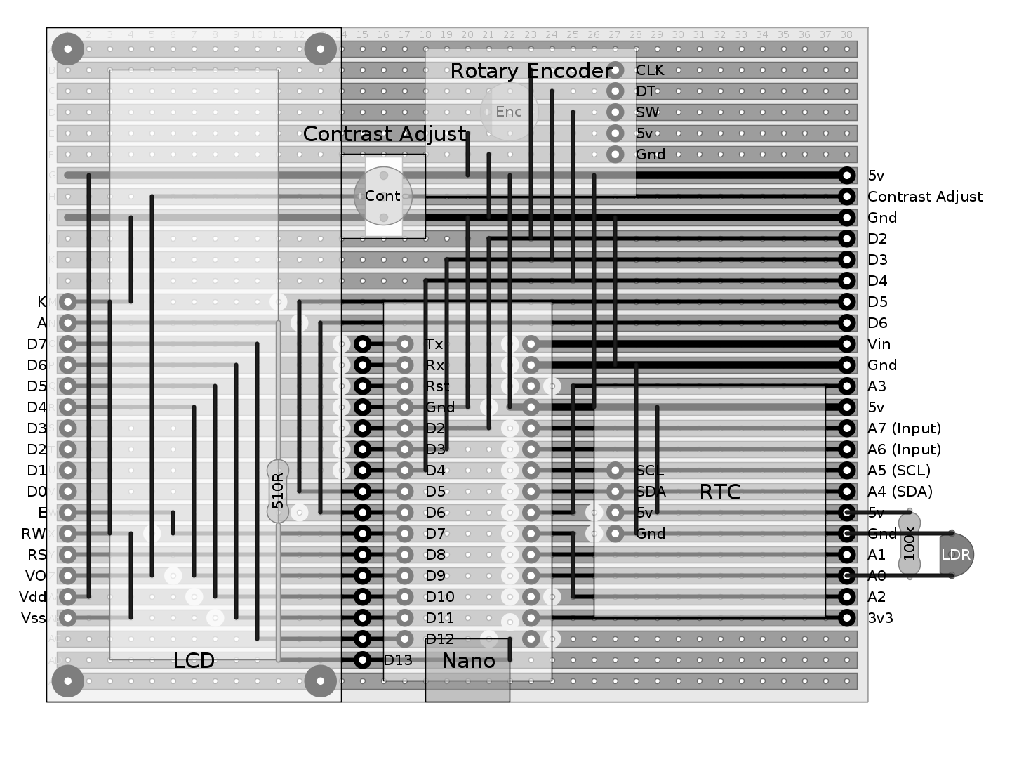
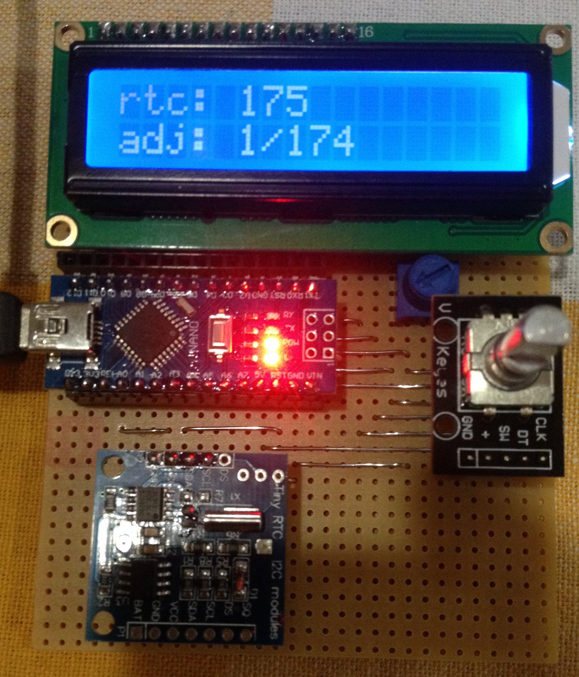
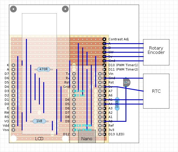
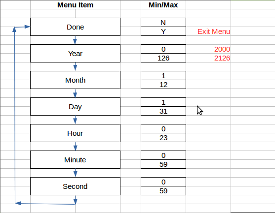
I have finished with this project. I have put a cut down version of the code, "RotaryEncoderBlink", in the files directory. It has a simple menu system that uses the serial port to set the blink rate.
It works fine providing you don't turn the encoder too fast (i.e. spin it!).
AlanX