-
The best way to shoot PCBs...
06/07/2018 at 16:45 • 6 commentsShooting PCBs with a camera, and then converting them into flat images can be frustrating. Fight with lighting, lens correction, perspective correction, remove blemishes, color correction, find the corners, crop... no wonder I don't do a perfect job. Lazy me just shoots, crops & uploads.
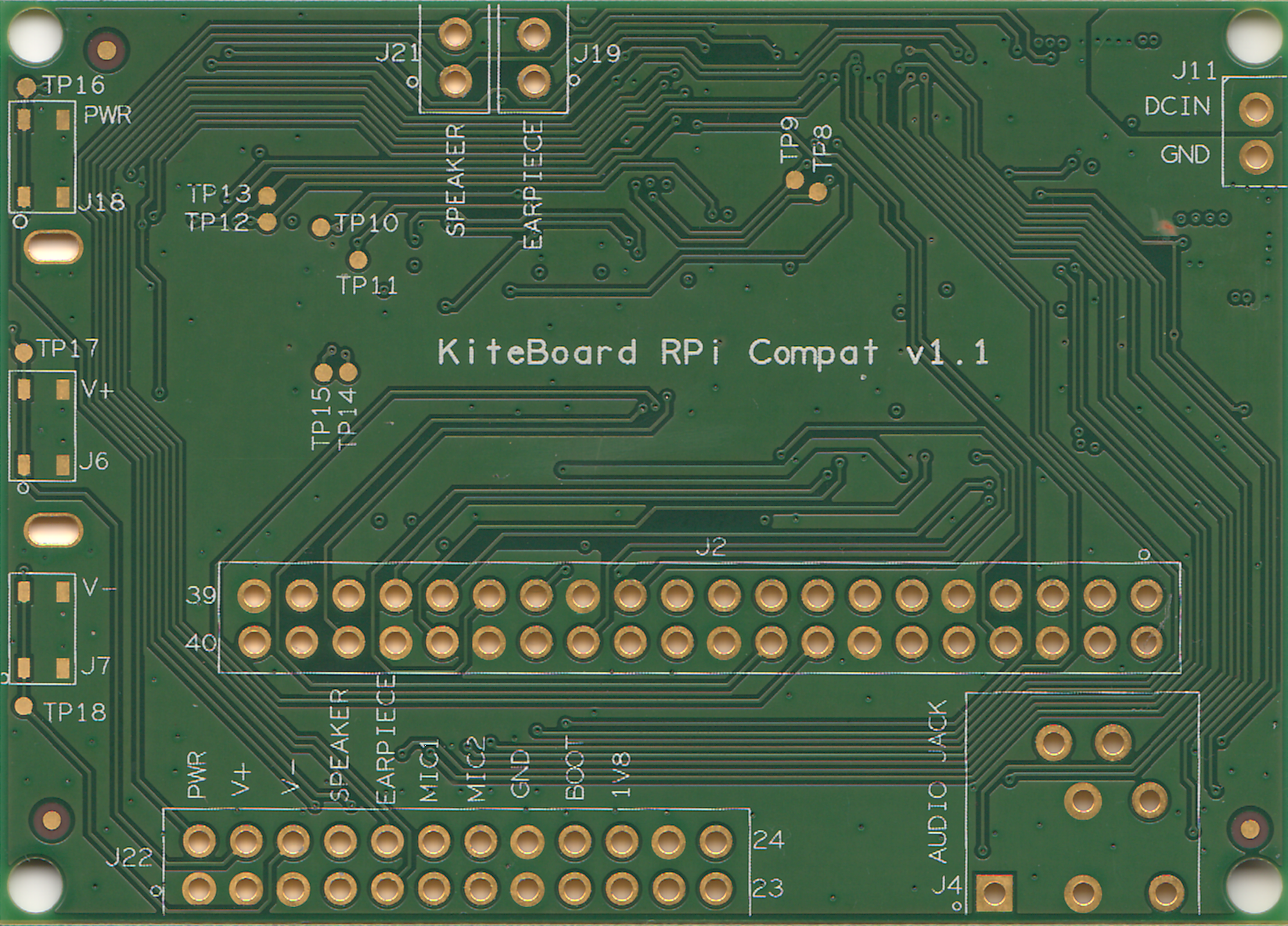
I seem to have found the best way to shoot PCBs today - don't shoot them, just scan them using a regullar flatbed scanner:
![]()
I like the color output from the scanner. The scan is perfectly rectangular. Crop & upload. Could life get simpler ?
(Of course, this technique won't work for PCBs with mounted components. But that's life.)
-
Kites Flying Around the World
05/19/2018 at 06:40 • 0 commentsIn our KICKSTARTER campaign, we introduced the idea of "Backers we Love" - basically anybody backing the project on KICKSTARTER gets a chance to try out a Kite. We now have Kites flying around the world as we speak.
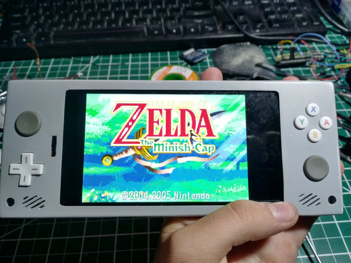
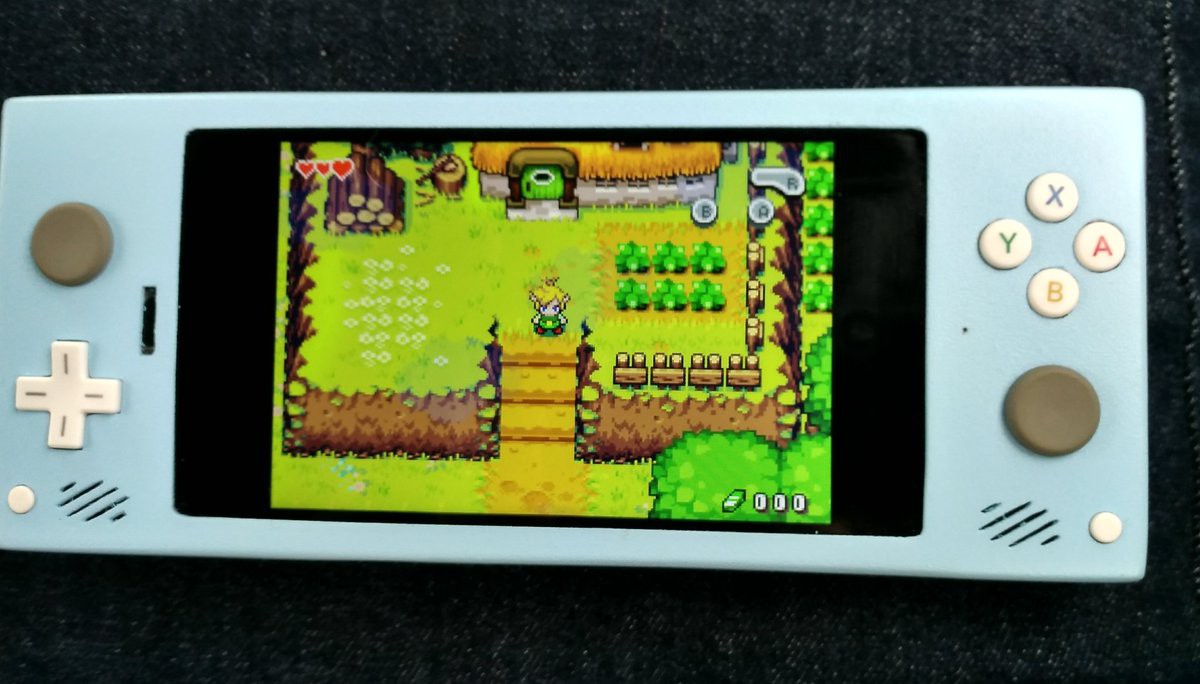
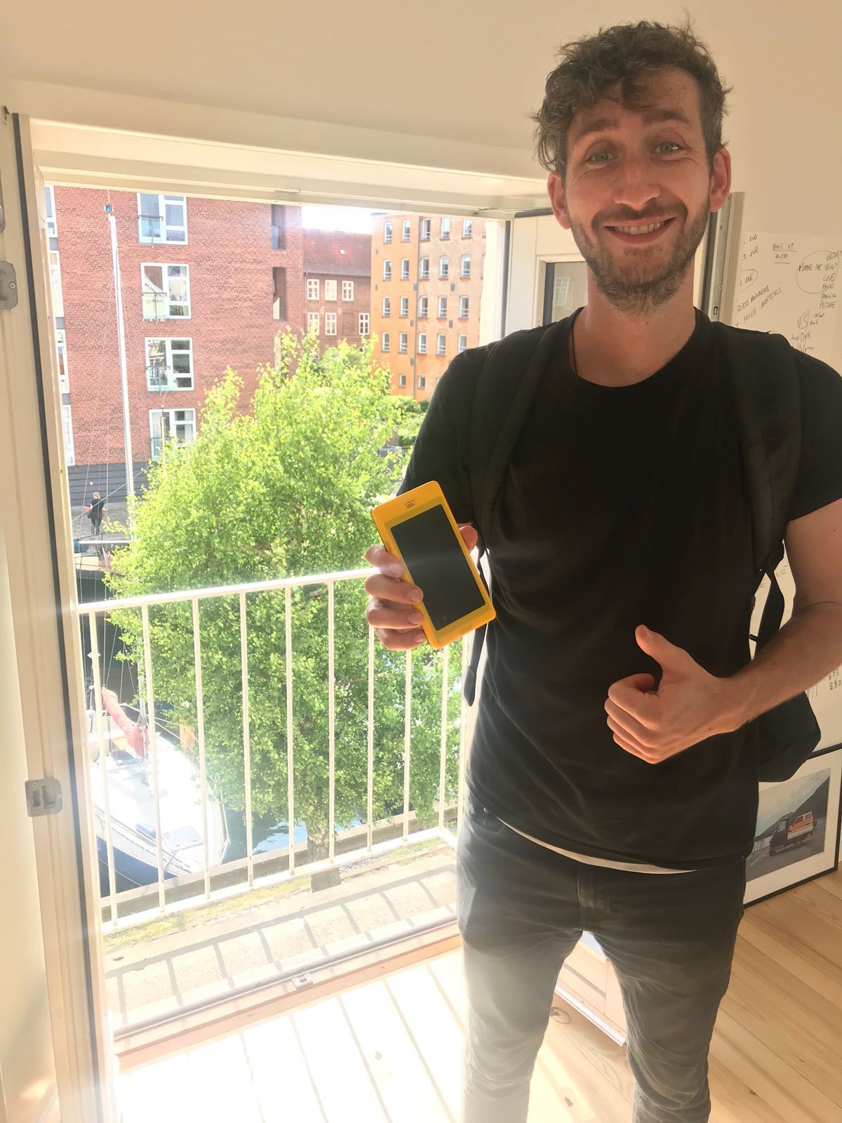
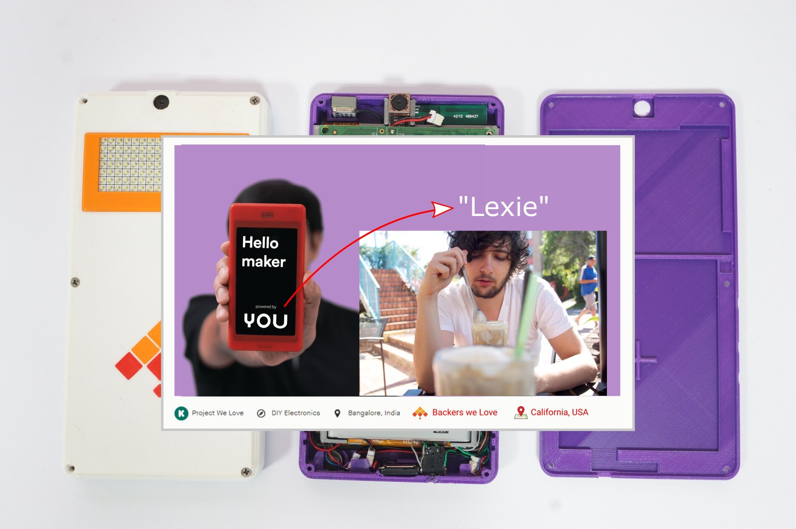
@Lexie Dostal got the first Kite - shipped to USA. Lexie is a windows game programmer. He has made a cool game controller Android phone with Kite (painting in progress):
![]()
Do checkout his twitter feed for more work-in-progress images. He has painted the case with a nice blue color, sanded it, and is making it nice & smooth.
![]()
This prototype will be shown at Maker Faire tomorrow, as part of the Hackaday Prize information session:
![]()
Lexie will also have a separate KitePhone with him as demo unit. If you are attending Maker Faire, do give a shoutout on twitter to @hxLexie.
On the other side of the world, @Stuart Longland has been flying one in Australia. He has made a quick review of the unit:
We have another Kite flying in Germany too - it's with an Apple fan! ... But that update has to wait for Monday.
One Kite is with Dave Hakkens (of Phonebloks fame! - he now runs Precious Plastics). We've passed on a unit to him for evaluation.
![]()
Our Kickstarter project needs a push at this time. I have been keeping track of the statistics of the project. Today, I was startled to see the following information on my project dashboard:
![]()
419 users waiting for a reminder before the project's funding ends !?! Why oh why. Please jump in guys - this project needs your help...
-
A sneak peek into Kite v2
05/09/2018 at 05:28 • 5 commentsBefore reading this post, I highly recommend reading "Design of Kite Open Mobile Platform".
Kite v2 is the upcoming design of Kite. We are crowdfunding for it on KICKSTARTER (do look at that page for a quick pitch, but without too many tech details)
Let’s look at the desirable properties of Kite v2; this is on top of everything that holds for Kite v1:
- Minimal phone model must be not require soldering, must be very quick to assemble & disassemble.
- Swapping custom hardware in & out must be easy
- Make a powerful, and more generic kit
- Maximize "open"ness
- Maximize local sourcing possibilities
In short, Kite v2 takes a good design, and aims takes it to the next level.
Design of Kite v2
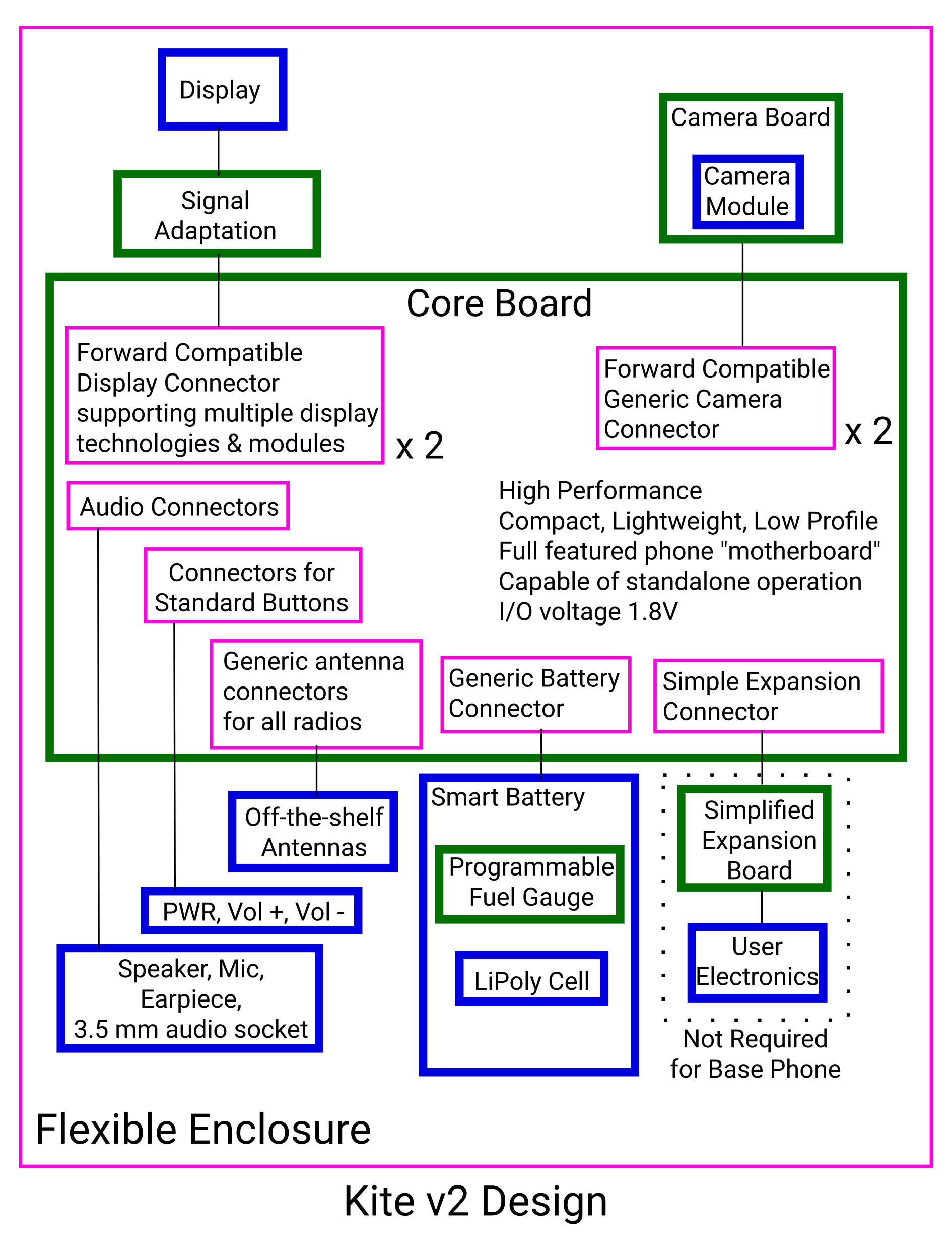
Let’s start with a block diagram treatment of the design being considered for Kite v2:
![]()
Compared to Kite v1, the Core board design has a few major changes. Let’s run through them.
We get connectors for audio & standard buttons right on the Core. This is part of the “soldering free” promise for the minimal phone on Kite v2. Pushing the connectors to the core has an interesting side effect: it makes the expansion board truly optional! Any user who doesn’t need the extra electronics can skip it (everyone will still get it as part of the kit, though). We think that the first assembly of a KitePhone for most users will not include the expansion!
Kite now includes add a “smart” battery component. This component integrates a fuel gauge (and protection circuitry) and a Li-poly cell. To get an accurate estimate of the state of charge (battery percentage), the fuel gauge is programmed with the characteristics of the cell. If a user wishes to change the cell, it’s possible to do that. To get accurate fuel gauging, however, the fuel gauge needs to be reprogrammed.
Finally, it’s not enough for display & camera connectors to be “generic” (Kite v1). We need them to be “forward compatible”. That way, we can upgrade KiteBoard to v3 in the future, while hopefully keeping the same peripherals (hopefully the camera too, but everything else will work 100%).
Kite v2 will include a camera board. Like the display, an intermediate board is the key to making the connector independent of the actual camera. The camera board is expected to be much simpler than the display board, and extremely compact.
We can reasonably expect to have more displays & cameras over a period of time. To accommodate this, we may need to implement a simple way to detect the peripherals. Simplest way to do that may be a simple I2C EEPROM on the peripheral boards.
Implementation of Kite v2
Implementation hasn't started yet (depends on crowdfunding), but we are at an advanced stage of design. Here's what we know...
Kite v2 will be based on KiteBoard v2. KiteBoard v2 will be based on Snapdragon 450 (was Snapdragon 625, but we had to change it) - bringing an across-the-board improvement performance in all areas:
- Faster octa-core ARM Cortex A53 at 1.8 GHz
- Adreno 506 GPU
- 2 GB LPDDR3 RAM at faster speed
- Faster LTE
- WiFi ac!
- BT 4.2
- USB 3.0
- Two independent displays
- Two cameras
Support for two independent displays will make things very interesting. A few combinations would be interesting:
- 2 LCD displays! The same display module will be usable on both connectors…
- LCD Display + HDMI option. HDMI could mirror the LCD screen, or show something independent.
- Dual head HDMI desktop with Kite!
- Stereo screen of some sort. There is no firm plan for this yet. This will be driven by community requirements.
The camera on Kite v2 will be much better – around 12 MP with faster auto-focus. Support for two cameras will make things interesting too. The camera module in the kit will be usable on both interfaces.
We are close to finalizing how the “smart” battery must be implemented. Two parts to this:
- Get a customized LiPoly fuel cell of 3000 mAh capacity. Get the shape customized to suit the phone design.
- Use a fuel gauge from a well known vendor – e.g. TI. We can use such a fuel gauge, calibrate & program this to the 3000 mAh LiPoly cell.
You are probably wondering why we need that fuel gauge. Globalization is great. But for many things, it makes sense to source local. Batteries are almost at the top of that list. We want to enable everyone in a reasonable way to use their own batteries. Many off-the-shelf batteries could be used with Kite – including 18650 Li-Ion batteries.
There are two aspects to getting an off-the-shelf battery to work great for users:
- Configure the charger (in the KiteBoard) with parameters that are appropriate & safe for the battery
- Keep track of the state-of-charge of the battery – important to show users the percentage of charge in the battery.
We already know how to do (1). Using a common fuel gauge helps any user do (2), using tools that are made available by the vendor of the fuel gauge – TI, in this case. A tool to tune a fuel gauge costs around 300$ US. That’s a great deal for anyone looking to build a custom device of any type… For common batteries like the 18650, we will provide the fuel gauge profiles ourselves, so everyone does not need to do that.
Additional Periperals for Kite v2
Kite is a “DIY Modular Smartphone” platform. The selling point of modular smartphones are the lots of “promised” plug & play possibilities. So, where does Kite stand?
Kite v2 represents a generic design. With the Raspberry Pi compatible HAT connector on the expansion board, we allow everyone to easily add custom electronics. Sensors, displays, buttons, actuators, other peripherals are all easy to add. Users who can do basic circuits are empowered to spin their own expansion board – which opens up exciting possibilities for everyone. The battery design is very generic too. The antennas were already generic, even in Kite v1.
That leaves the focus on display & camera. Let’s tackle the easier one first – the camera. When most people think “camera”, they think “pretty pictures”. That isn’t necessarily the case. There are other camera possibilities too, such as:
- Cameras that capture raw images for special purposes – e.g. dedicated barcode scanning modules (these generally include special illumination techniques, commonly a laser LED)
- HDMI Input. Idea is to make a HDMI output from another camera, laptop, desktop or anywhere else look like.. a camera feed! This will sure to result in many great use cases!
- Many other special purpose cameras exist, and work over USB 3.0.
The USB 3.0 category of cameras are likely to be easy to interface by users/developers themselves – possibly aided by the vendors of those cameras. However, the other two (and the “pretty picture” cameras) will depend on the proprietary camera interface. Interfacing such cameras does require a lot of work & expertise.
Due to the nature of the CSI interface, it will unfortunately remain closed in Kite v2. We could implement camera-centric requirements – if there is enough demand. We don’t need to second guess what special cameras our users need, as we rely on our users to tell us what they think is important. We then assess feasibility & costs. If an interested group is happy with those, we implement & deliver the feature. Essentially, the feature becomes a “group buy”.
What about the display, then? Well, the display interface will be an open interface that we will document. Interfacing a display is a lot of work - but way less than anything required for a camera. The number of people who know how to interface displays certainly out-numbers those who can do cameras, at-least in a 100:1 ratio, if not more. So, the open display interface will be very useful for people. I imagine that there will be at-least two types of users:
- Folks who make a new display work for themselves. A hobbyist/maker doing this is likely to share their results, making them usable for everyone. A professional/startup is less likely to do the same. This category of users may not need much help, given our documentation.
- Users who “want” a display with a certain specification.
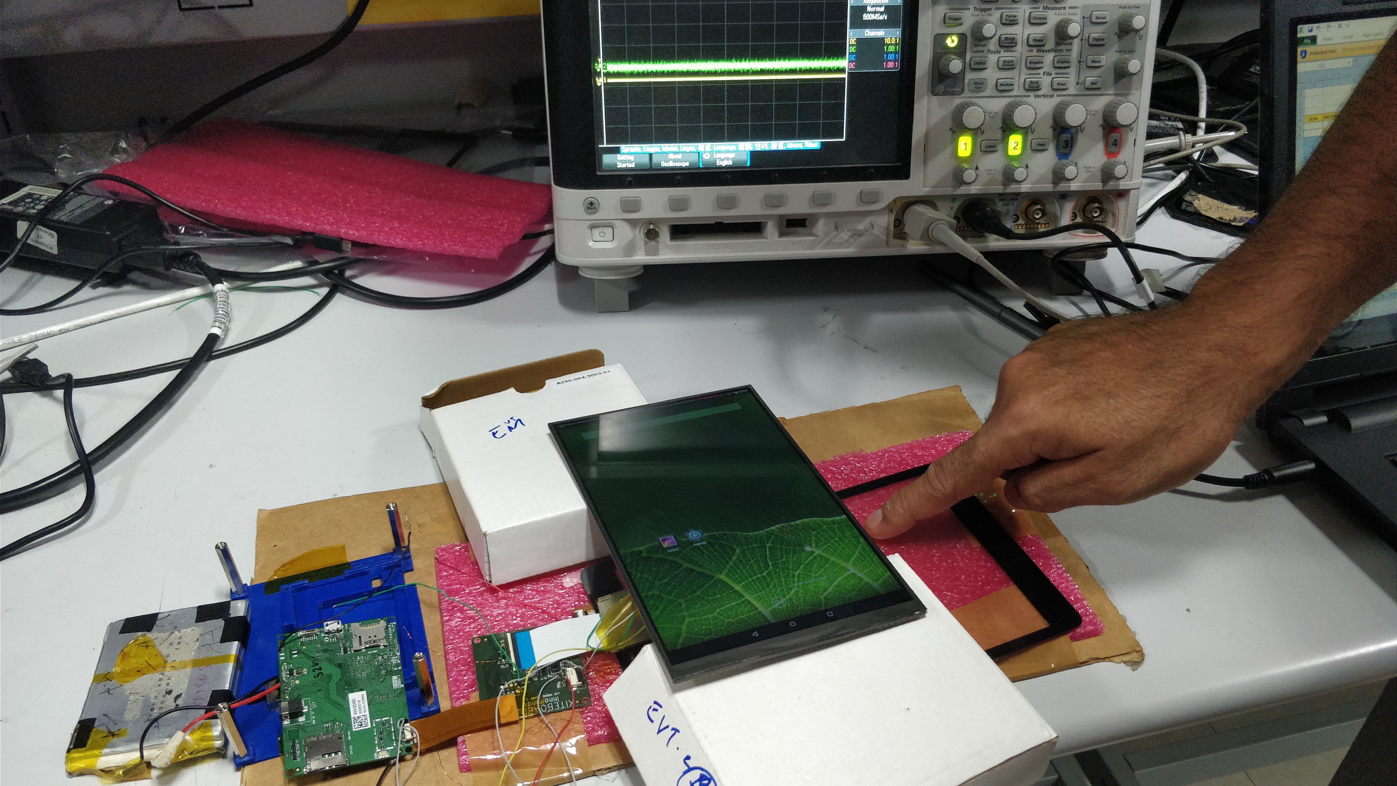
We can make available many types of displays of various size. Just like the camera, we do this based on demand, feasibility & costs. Here's a bit of proof - an 8 inch display panel with touch, running with Kite v1. The touch panel is the separate black frame: (trivia: the battery is 6000 mAh LiPoly, and note the wires running from the display board - it's hand wired, zoom in to see them! display is 720p resolution)
![]()
Let me state this again, very clearly : With Kite's design, making displays & cameras available as standard peripherals is a market & cost problem, not a technology hurdle.
I can also imagine (assuming that this project gets successfully funded on Kickstarter), that hackers will take a great liking to the open display interface. Why so? With our documentation, this elite class will start looking at spare displays available for common phones, and see if they can be made to work with Kite. Some reverse engineering with an oscilloscope will be required, to figure out which pins are what on the proprietary connector(s) on those displays modules. If the Linux kernel sources of those common phone are available (yeah, GPL v2, but not every vendor complies), then the necessary software information for bring-up is already in place. You won’t need a datasheet of the display panel to do the rest… Same goes for the touch panel. This will be great tidings for everyone concerned. Next steps: Create a new display adapter board, and ensure both the display & touch work. Change the case to hold the display (modifiable 3D designs make this a snap). And go for glory… Or, sell it on Tindie! This is not mere theory; I see at-least one MIPI display interfaced on hackaday already: the iPhone 4/4S display. With Kite available to everyone, that number is sure to go north very quickly...
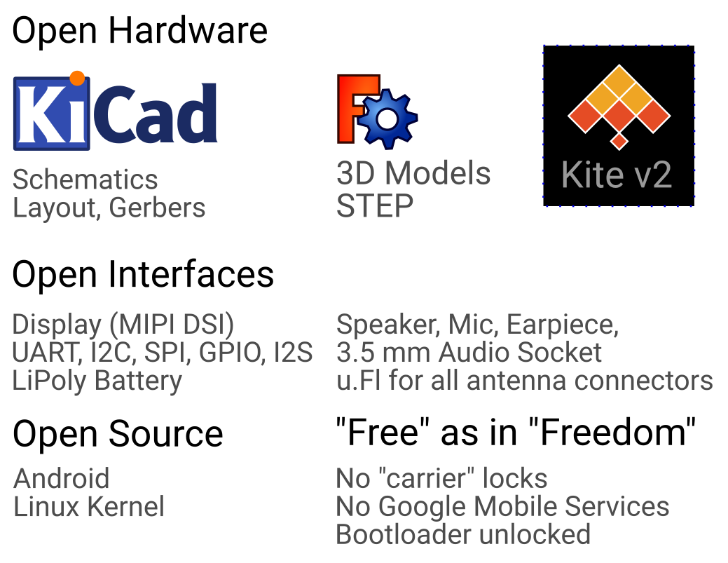
Here's an openness summary of what we are aiming with Kite v2. Open enough for you ?
![]()
A note on the "open hardware" aspect, though. We will be open source, but fully IP compliant at the same time. Meaning that partner/vendor/silicon datasheets will be open only if they allow opening it. We expect our software & documentation to cover the closed parts in a reasonable & helpful way. There will be software blobs for various closed pieces, as is common in Android: GPU, modem, WiFi/BT, camera, sensors (maybe).
In many ways, I can argue that Kite v2 empowers folks interested in the mobile world, in a way much similar to what the Raspberry Pi does in its segment (19 million Pis a couple of weeks back, congrats guys!). Kite v2 gets high-tech into the hands of makers, students, professionals/researchers, startups, educators and discerning consumers, prosumers and even activists (right-to-repair, freedom from various locks, open app ecosystems...). Kite is the swiss-army knife of mobile computing. It's an empowering vision for a potentially large user community, who have no access to great technology that is already in everyone's hands!
The Hackaday Prize 2018 contest was announced many days ago. It took me a few days to convince myself that this project is a good candidate for it. “Build hope. Design the future” - those lines do apply to this project. Not just in what we do – but in what we allow everyone to do. When that realization dawned on me, I submitted Kite as my entry to the “Open Hardware Design Challenge”.
-
Woohoo! We are in the finals!
05/04/2018 at 08:45 • 0 commentsGot the great news - we are in the finals of the Hackaday Prize 2018 ! This project is competing under the "Open Hardware Design Challenge". A great honour for this project !
![]()
The details of the announcement are at this link ! Thanks a lot everyone for all your encouragement too.
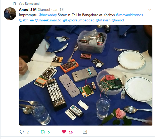
This project branched off to hackaday after a meeting of hardware enthusiasts!
![]()
These guys dropped the apple on my head. Open hardware is the way to go, I said! I am happy to make this idea grow further and become 100% open hardware with our crowdfunding attempts at KICKSTARTER for Kite v2.
Please back this project there and help Kite v2 reach everyone! Thanks a lot!
-
Can the makers & hackers show up at the party, please ?
04/24/2018 at 18:52 • 0 commentsHello hackers, makers, DIY enthusiasts, etc!
A quick introduction for those of you who don't know me: My name is Shree. I am trying to bring a novel idea into this world. The idea that you can make your own smartphone. Free of chains, in every way. At $300 a piece, roughly. I have launched a campaign on Kickstarter to realize this dream.
I have a little more than 25 days from now to make this happen. I need close to a million dollars to make this happen. That's not chump change, I know that. But it's the smartphone we are talking about here. A million dollars is chump change in that business. Achieving freedom for a smartphone is no small deed. But there is a price to pay, and it is not too high. Individually maybe yes. But collectively ? No.
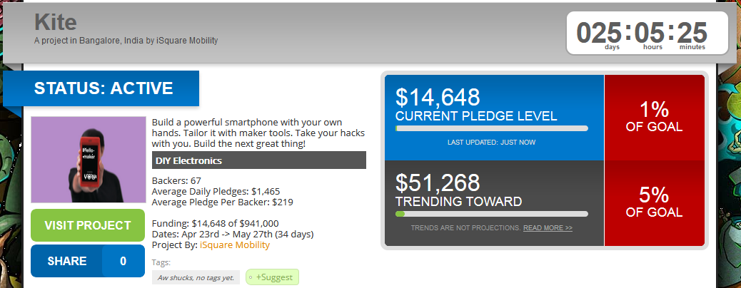
My campaign has been live for a few days. There is a site called kicktraq that helps campaign creators understand their chances. It's not perfect, but it's probably not too bad either!
We are showing an interesting downward trend.
![]()
So, the simple prediction seems to say that this campaign will fail ? I refuse to believe that less than 200 people in the world need a DIY smartphone kit...
I need your support to make this successful. It's a community project designed to save 10% for everyone by avoiding a "publicity/marketing" budget. If you care about this, then you should help me. Not just for me, but for yourself too.
Kite solves many technology problems. I can give you proof for that:
- Look at the pages of the Kite Open Hardware Android Smartphone project, you will find that I have already made this happen in a large way. If you think that's a fancy claim, let me know & I can explain why it is not.
- A reasonably complete story is told well on the kickstarter page - it was long to begin with - but we've made it simpler now.
Please note that I am only looking to take Kite to the next level here - make it soar, into your hands. I am asking money from you guys to upgrade KiteBoard to v2, running some required safety certifications, and achieve a reasonable volume (3000 pieces) without burning my own hands.
If you interested to try out Kite, please pledge to the project. Our very own @Lexie Dostal is trying it a Kite in California, USA, as we speak. We call this the "Backers we Love" program in KICKSTARTER.
![]()
If you are reading this far, please note that I need your support. Back this project on KICKSTARTER and I will do everything in my power to do what you need. I have the technical know-how - but marketing is not my suite. That's why this project is on hackaday!
Please back this project on KICKSTARTER. You don't have to back the kit if you don't want to - even a "Thank You" ($5 or $1) will do! We can go a long way...
Note that I do appreciate & understand that not everyone needs this. Frankly, this is not a problem for this project - we only need 3000 people to make this happen! Every donation helps too, and we will use those to ship free kits worldwide to backers.
However, if you don't feel like backing the project, then here is my humble request: Please tell me why! Give me the reasons why you do not need it. If you have any need that is not met by the project, please let me know. I can find ways to fix things, but not everything. I am talking of technical solutions. That's what my project promises!
Finally, do help to share our campaign. Share it with your friends. Let me hope that the hackers, makers and everyone else shows up to the party, before it is too late...
Thanks a lot...
-
Kite is now Live on Kickstarter
04/23/2018 at 14:31 • 0 commentsI am excited to announce that Kite is now LIVE on Kickstarter!
Basically, we have kits available at $274+shipping right now. Please back the project . I can tell you that Glory Days of Open Hardware are ahead - if we do this!Thanks in advance & hoping for your support. If you have any questions, please let me know..
-
Kickstarter Launch : 23rd April, 2018. 7 PM IST (GMT+5:30)
04/21/2018 at 16:50 • 0 commentsHello World!
Yes, that's right. I am preparing for a massive launch on Kickstarter. The countdown has already begun... to free the Smartphone !
![]()
We have subscriptions from USA, Canada, Mexico, Ecuador, Brazil, South Africa, Spain, UK, France, Belgium, Netherlands, Switzerland, Germany, Italy, Austria, Sweden, Bulgaria, Lithuania, India, Russian Federation, Thailand, Singapore, Vietnam, South Korea, Australia, New Zealand and Japan. Phew!
Apologies, but I would rather not try to convert the launch time to your time zone! Here's a handy conversion link.
Thanks to all who have subscribed..If you subscribed to our mailing list, you should have got an email already with the launch information. If not, please do check your spam folder! There is still time to subscribe at www.kiteboard.io/contact ! I look forward to your support... KitePhone is coming to Kickstarter...
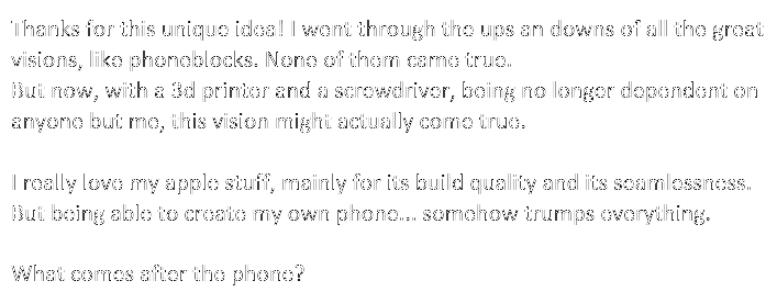
And this, I think, is the an important indicator of what is going to happen. I am thrilled to receive this message from a potential backer:
![]()
That's an empowering vision - but written by someone else, and someone who uses Apple products! Who would have thought?
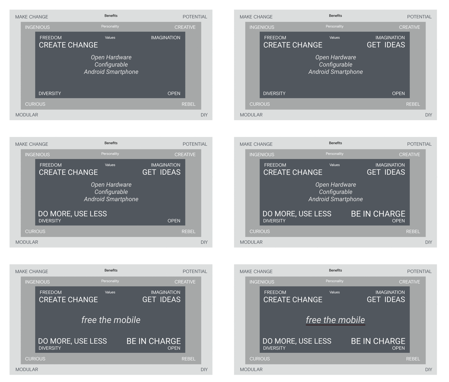
This is the gist of our quest - the personalities that we are after!
![]()
To make this idea a reality, I really need your help! In fact, we all need all our help. I said it on twitter in the morning, and I will say it again: Is this history in the making, or an empowering idea that will go down the drain ? You will get to decide, over the next 35 days.
-
"Feature Requests" in the Democracy of Kite
04/17/2018 at 20:33 • 1 commentThe more I think about Kite, the more interesting I find it. It is not about me being the creator of Kite. It’s about the possibilities that are open for everyone.
Kite is, first and foremost, a hardware freedom project for Android. Android is the most prevalent open source platform for phones. There is no open hardware for Android. Kite aims to be that platform. That’s the primary reason for the existence of Kite!
What sort of freedoms are these? Any antenna, any battery, lots of your own hardware you can add, and of course make your own enclosure/case. We provide Raspberry Pi HAT compatibility – but that’s just a simple board (with a few level converters etc) that anyone can change to adapt to any system. No restrictions there either.
This immense freedom in hardware makes the software freedoms more than meaningful - it raises the hardware software combination to a level of freedom never attainable before by the masses.
A whole lot of people are sufficiently empowered to do some bits of hardware, courtesy the maker movement. However, the real problem is in the area of software. The sort of hardware freedom this project gives has been the territory of OEMs. Phone vendors. Folks with big pockets. Most of the freedoms of the underlying platforms are suppressed by OEMs to deliver consumer goods; this is not wrong! It’s the nature of their business. Kite makes those goodies available. Kite shows you how to mod Android to achieve your goals. We provide a great starting point so that you can achieve what you want to – without us getting in the way. That’s what we call, “empowerment”.
Kite begins as a hardware project with a standard configuration – Kite v2. The hardware configuration of Kite v2 is setup in a way that attracts maximum users at a fair price point for everyone. This is one of the tricky parts of the project.
The backers of the project are the citizens of the “democracy” of Kite. Each one effectively is a “voter”. Voter for what? The direction of the project. Note that it’s too early to ask/answer questions like, “if I buy ten kits, will I get ten votes” 😉. Thing about this democracy, like any democracy in the world, is that each voter will have a different interest & agenda.
Even me, the creator of the project, can’t predict how this democracy looks like. I can bet, though, that's it is going to be quite diverse. So, before deciding the future direction of the project, we let the community form. Kickstarter ends successfully. And lo & behold – here’s the community. The democracy of Kite.
What next? Now, people are free to come up with their own list of what they want us, the creators of the project, to focus on. This is what we call “feature requests”. Feature requests can be related to hardware or software. Let me give you some examples.
Hardware features: 5” 1080p screen, barcode camera, “can I make a tablet with Kite?”, and anything else that you may imagine. There is a large ecosystem of component catering to the mobile, handheld & PDA industries - and it's not only in China. We can tap that as required.
Software features: Can I dual boot linux? How to get <piece_of_hardware_X> working with Kite? Can I have an API to control that camera focus distance from Python? and anything else you may imagine.
How do we act on feature requests? In a reasonably democratic manner. Let’s tackle the hardware first. Hardware may involve costs, but not necessarily always. E.g. “how do I use that 18650 battery with Kite” is likely to come at zero cost. That flexibility is engineered in Kite; it’s a matter of configuration of the fuel gauge chip & the charger.
That said, most hardware features involve costs. That’s where the democracy kicks in. More people interested in the idea is likely to lower the cost of implementing the solution. That’s how hardware works. The proposer of the hardware puts up an idea or a requirement. People “upvote”. Based on the votes, we – the creators of Kite – decide the feasibility & cost structure. If feasible, the feature request may become a group buy. All feature requests follow our "Openness" principles. Boards will be open hardware. Software could get tricky depending on the exact area. The camera stack is closed (due to the complexity & NDA stuff) - so that part remains in binary blobs.
It is important to understand that this is not a scheme to corner all the hardware revenue. With community development, we expect that our involvement should come down. But hardware evolves, so we can’t be so sure just yet. And, not everyone has the skills to do displays & cameras. With time, folks may develop such skills. That is the hope – but until that utopia is in sight, our involvement as “experts” is required.
Let’s look at software features next. Same rules apply. Upvotes. Feasibility. Software features look deceptively simple at first, but they suck time. That’s where we exercise care. We allot time carefully. The bar for software may be higher, as a result.
That last point is very important. Many people are asking for Linux. That’s well understood. If there’s something that sets the Linux community apart, it is that passion. But like I said – this is not something that I decide. The community decides the direction. When the community is willing, the creator kicks in!
Makes sense?
-
IMPORTANT: an update (Crowdfunding D-Date: 23 April), and a downgrade...
04/16/2018 at 15:31 • 7 commentsThe important update first: assuming all goes well, we should be launching our Kickstarter campaign on 23rd April, 2018 (i.e. exactly one week from now). I do request anyone who has not done so to subscribe at www.kiteboard.io/contact . Among other things, this helps us understand the *cellular* requirements. Please subscribe if you haven't already. Thank you.
Now, to the other part: I had earlier communicated that we will launch with the Snapdragon 625. I regret to announce that we will not be able to do so. Instead, I am forced to settle for the Snapdragon 450 (for reasons read below).
This downgrade effectively means the following:
- No 4K video encode/decode. (450 is limited to 1080p)
- The application processor is 1.8 GHz, instead of 2.0 GHz
- Reduces L1 cache by half - ouch ! (SD450 is 512 KB, compared to 1 MB in SD 625)
Summary: lower performance in some areas (I am not able to figure out the GPU performance difference. Any info here would be useful). How exactly it will impact you, I will leave you to decide that. Sorry for the change. I think it's better to do this right now.
I have mixed feelings about this, to be honest. Of everything, I was hanging onto the SD 625 for the 4K encode/decode capabilities. I am sad to see it go.
So – why did I decide on the Snapdragon 450? To answer that, let me tell you what I think are my responsibilities are in this project:
- Get great technology to everyone’s hands. Larger the community, better for everyone.
- Ensure that we have a great, predictable & deliverable plan. Once I start my campaign, there should be no going back. (If I am to lose face, now is a great time!)
- Run the project, with my team. Deliver as promised during the campaign.
This project includes certification plans of all sort. Global LTE will require us to have two SKUs for KiteBoard v2:
- North America (USA, Canada)
- Europe & Rest of the World
The largest number of folks who are likely to back this project will come from USA. My subscription list tells me that. Kickstarter provides a “Community” part for every project. A cursory scan on a few projects – and surely projects in the DIY Electronics category – will help prove that too. I expect 40-60% of my backers from USA, if not more.
So – USA is an important geography for this project. USA is also a problematic area for cellular connectivity – courtesy carriers & carrier certification requirements. Countless projects have been delayed due to cellular certifications. And famous ones. I am talking about people with deep pockets. I don’t want to add to that list. I have a great plan for predictable, on time delivery – if I stick to the Snapdragon 450.
But that’s not the only reason. Another equally important reason is that I am unable to see who is buying the Snapdragon 625, and for what purposes. This project is expected to deliver in Dec-Jan window for the early orders. 8 months is a long time in this business. And if I don’t have this visibility now, you can imagine what will happen next year. I need a minimum of 3000 backers, but that’s the minimum. I intend to do a great job – and that means that I should expect more people backing me.
With larger volumes, and longer life, comes a predictability requirement. That’s where the Snapdragon 450 scores again. It’s a fresh chip. The Snapdragon 450 also has most of the goodness of the 625 – two independent displays, two cameras(wee bit less powerful), USB 3.0, WiFi ac, and everything else, including Cat 6 LTE. What you lose is what I have mentioned earlier. Whether it’s worth losing that to get what this project gives you - that's something you need to decide.
There are other benefits of the SD450 being a “fresh chip” – software updates, and more value addition that could potentially be added by Qualcomm (APIs, and anything else). There could be a hidden benefit with the SD 450. Google has mandated (and I quote) that "All SoCs productized in 2017 must launch with kernel 4.4 or newer". To all external appearances, the 450 was productized in 2017. How “productized” is defined by Google isn’t really known to me, but at this point, I am free to speculate that Kernel 4.4 is a likelihood for Snapdragon 450. That should be cause for some cheer, however speculative that might be.
Also, with the 450, I have great visibility into the certification cycle. Whatever I publish when the campaign goes live, I am sure that’s eminently deliverable. So, that’s why I have my mixed feelings. My feather in the cap is lightened, but I have a great chance of making it a feather in everyone’s hands in a timely manner. With that, I rest my case!
Over to you guys. Let me know what you think!
Brickbats & comments welcome... I have edited the rest of the pages to change the processor from 625 to 450 too. The places where I changed the spec have a link back to this article. Hackaday seems to have no way to do overstrike text. (I wonder why for that last part)
-
Design of Kite Open Mobile Platform
04/08/2018 at 14:41 • 3 commentsFor the past couple of years, me & my team have spent a lot of time working with & refining Kiteboard & Kite. Things kind of evolved to reach the current state. Looking back, I can’t find a single document that anybody wrote which summarizes the design in a useful manner. This post is an attempt to explain what has happened till now, and how we intend to change things in the future.
Before we go into design, architecture, etc, I would like to offer a simplified bird’s eye view of what goes into creating a phone. I am painfully aware that it’s a simplification of a rather complex process fit into a few short paragraphs. If you are an expert, please excuse any inaccuracies in the next few paragraphs 😊Smartphones are based on SoCs – basically a lot packed into a single chip. SoC vendors (Qualcomm, MediaTek) don’t stop at providing just SoCs, they provide complete reference designs for phones. Generally, a reference design tightly integrates various chips from the same vendor – the SoC, a PMIC (power management IC), WiFi/BT, RF circuitry, and Battery Charging. Reference designs also include other parts required to build the full phone: RAM, storage, peripherals, connectors, antenna designs, and everything including the enclosure of the phone. A reference design generally provides several alternatives for various components (it’s a huge market, choice rules!). Reference designs represent reasonably tuned solutions, from a hardware, software, cost and performance perspective (that is saying quite a lot in one sentence, by the way!).
Most smartphone vendors leverage the reference designs, changing mostly the “peripherals” – display/touch, cameras, maybe sensors, casing, battery. Peripherals & the base platform decide the market positioning of the device. Making a smartphone is a tight exercise in space optimization too. For every device, shape of the board and connectors on it are changed to accommodate the selected peripherals & the overall design. Antennas are designed & positioned carefully, and are highly influenced by safety testing (SAR) considerations.
Overall, a complete smartphone is a single block of tested hardware & software. It is “hard”ware – hardcoded (in software terms) to achieve a single, cost optimized device. Mass market consumer devices essentially go through an aggressive BOM optimization, which eliminates unnecessary components – down to the lowly resistors. Smartphones are designed to sell in the millions. Even a few wasted resistors are a no-no at that scale.
Reference designs are the secret to the flood of devices you have been seeing in the market for the past N years. Most devices based on any given platform don’t differ much in terms of performance and feature set.
Abstract Design of Kite v1
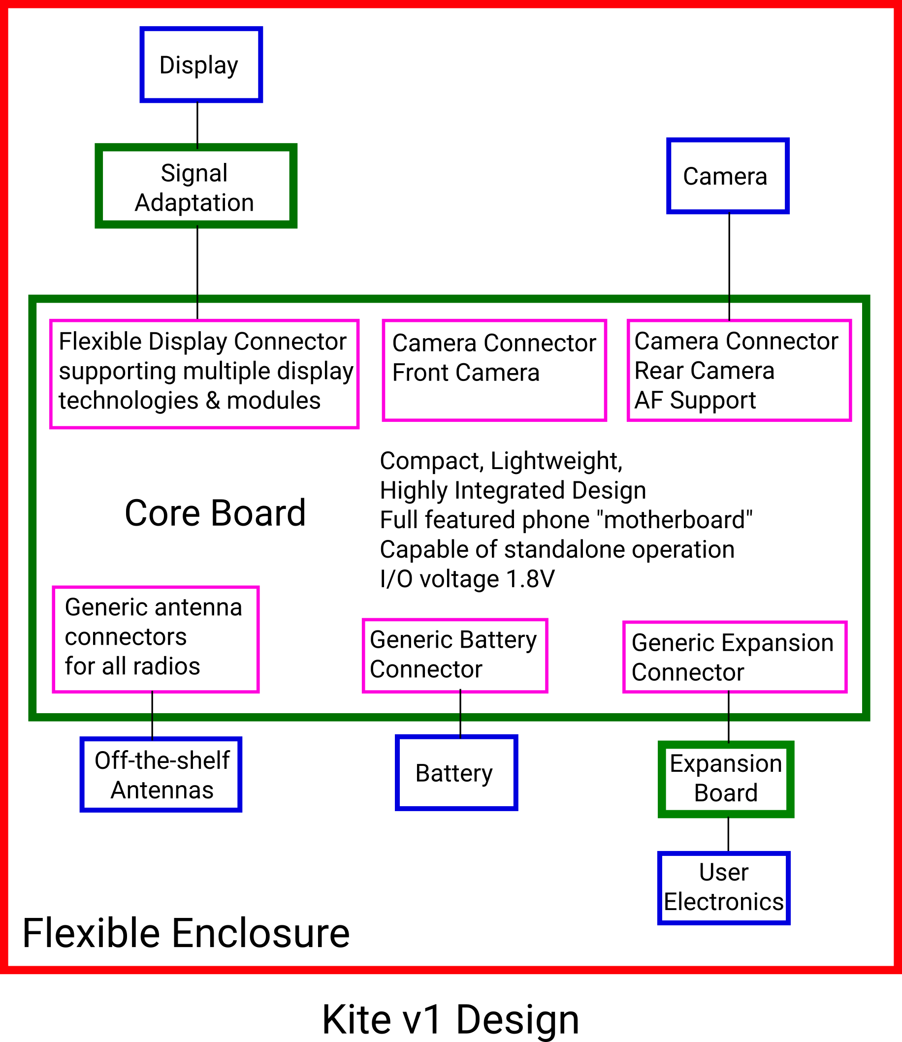
We wanted to create a design that would allow us to build a variety of devices using a standard set of components. Here’s a block diagram that reasonably captures the design of Kite, in generic terms – without reference to specific technology:
![]()
Before I get down to explaining each piece, here is the color coding used in the block diagrams in this post:
- Green for PCB
- Blue for peripherals
- Pink for connectors
At the center of the design is a “Core Board” (henceforth shortened to “Core”). It’s basically the guts of a full featured smartphone… If I were to draw an analogy with the PC, I would call it the “motherboard” of a smartphone. Basically, this includes the important, tightly integrated parts of the reference design. It skips most of the peripherals, opting to route necessary signals to connectors.
The connectors on the Core are kept reasonably generic. This gives us the flexibility to change the peripherals, without changing the Core.
The expansion connector on the Core includes important signals that allow us to create custom devices of various form factors. All the signals a user needs to add their own electronics must come here.
User electronics may operate at a different voltage level (3.3/5V) compared to the core. An expansion board can take care of the signal level conversion.
The battery connector on the Core must support everything required to connect & monitor the status of any battery.
The display connector on the Core needs to be generic enough to support multiple display technologies:
- Mobile displays with integrated touch panels
- HDMI monitors with audio output
- Other panels like LVDS and RGB
Since the display connector is generic, it cannot connect directly to any display in the world ! The required signal conversions can be done by a display specific display board.
Similarly, we need camera connectors. However, we can afford to be a little less generic (and specialized) in the case of cameras, as they are specialized devices (compared to displays, at any rate).
A phone includes various type of RF antenna: a primary RF antenna, a diversity RF antenna, a WiFi/BT antenna and a GPS antenna. The signal lines for these can be routed to a generic connector, once for each antenna.
Once generic antenna connectors are available, commonly available off-the-shelf antennas can be attached to them.
Finally, all this can be enclosed in a flexible enclosure, that allows customization by users.
Implementation of Kite v1
Abstract designs are great – they help us think in generic terms. When a design is converted to an actual physical implementation, important decisions (and naturally, trade-offs) need to be made.
Before I explain the actual implementation, I need to explain the general philosophy around the implementation. Early on, I realized that a DIY phone making kit must have the following desirable properties:
- Must be a flexible kit.
- Must be based on off-the-shelf components to the maximum possible extent.
- Must rely on consumer grade 3D printing (FDM) for making a case around the components.
- Must allow user to add their own electronics. After much thinking, I mapped this to a requirement of implementing a 40 Raspberry Pi HAT compatible connector.
- End device must be compact enough to be called a “phone”. However, size reduction must not trump accessibility for the hacker.
- Simple design, easy to assemble.
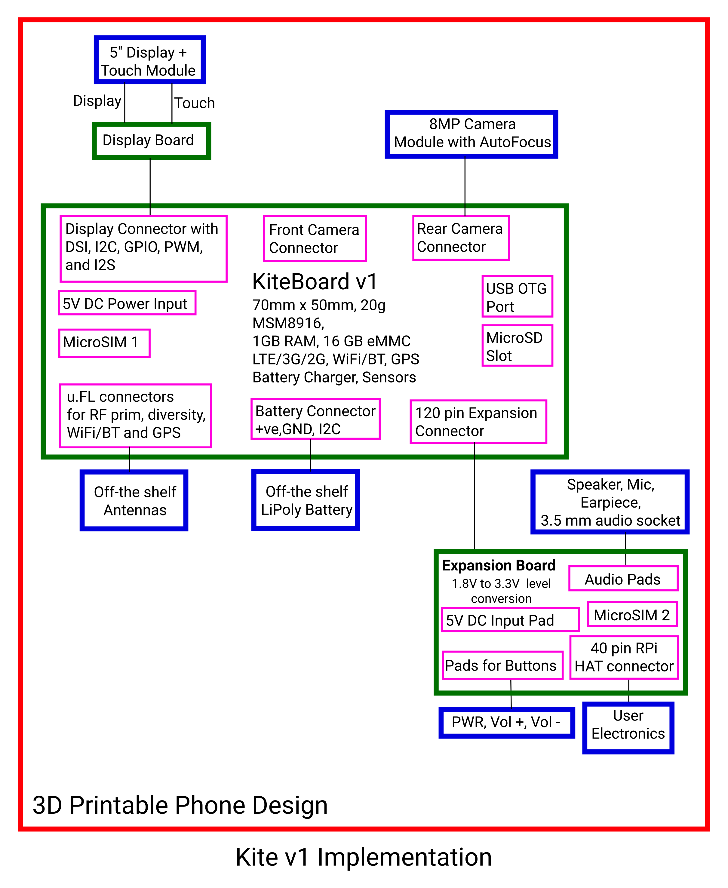
Now, let’s see how we mapped the design to the implementation of Kite v1, with the philosophy in mind:
![]()
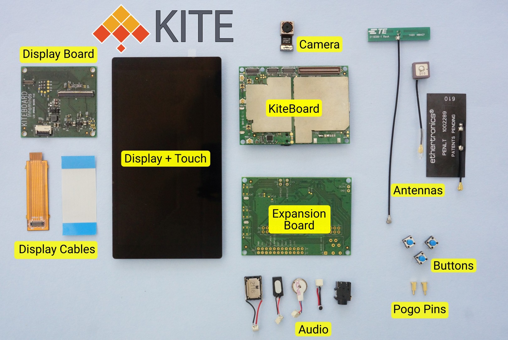
And here is Kite itself:
![]()
The picture above will look familiar to those who have read the log post about Poorna, the minimal phone built with Kite. Note that the design files (3D models, schematics) are available.
KiteBoard v1
The Core of the design is implemented in the KiteBoard. First things first – KiteBoard was not created exclusively only to make a smartphone (i.e. “Kite”). During the course of many years, we had seen that customers more or less wanted the same device with some differences. KiteBoard was an attempt to create a common platform that could meet diverse needs.
Individual makers & professional device makers (i.e. companies – my normal customers) have some requirements that are divergent. Professionals want to create something cost optimized; they generally don’t mind complex designs. Individual makers/startups need access to complex designs in a way that they can use. Commercially available boards that target makers generally have large connectors, 0.1” spaced pads, among other things. Several companies make available “SOM” modules that target the pros – these are generally hard to use standalone. Where do we draw the line?
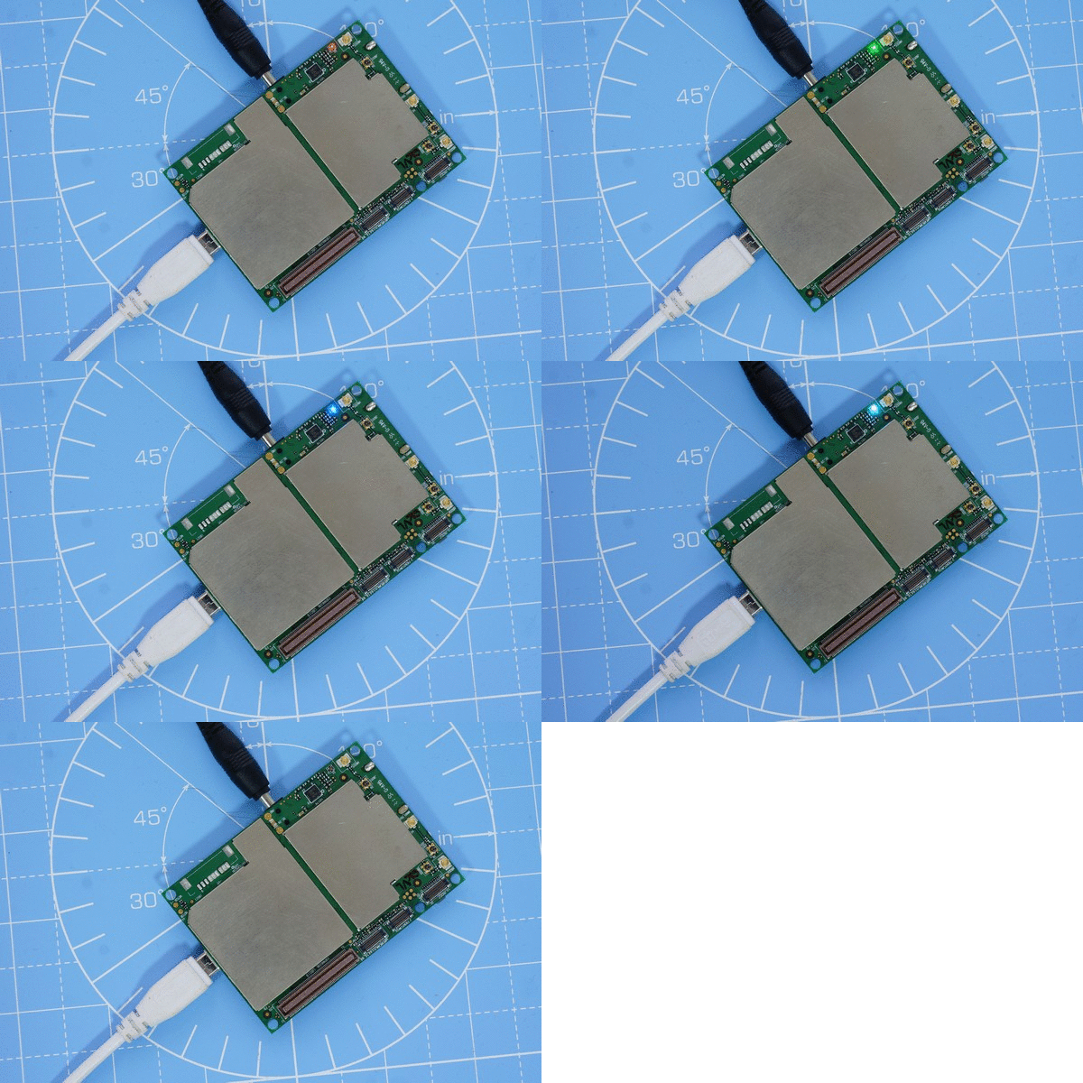
After much deliberation, we settled on a hybrid SBC/SOM approach to create KiteBoard v1. KiteBoard was implemented with MSM8916, a successful global platform not just for smartphones – but also for us. KiteBoard includes the “core” of a phone – integrating 1GB RAM (+16 GB storage), LTE/3G/2G, GPS, WiFi/BT (+FM radio too!), and battery charging with a dedicated DC option. Plus 9 axis accelerometer, ecompass, gyroscope. KiteBoard is designed to be standalone. So, we added a microSD slot, and a micro SIM slot. The selling pitch was, “power it on, and it will boot to Android & connect to the internet”. We implemented the required connectors on KiteBoard. KiteBoard has a RGB led on it, here’s the mandatory LED blink in action - with a slight twist: we have a tiny RGB LED on board - so we do an RGB dance. DC jack & USB are both connected. In the animation, below the red led looks a little weak - it's not so in real life...:
![]()
The following commands were used to do the animation, in the adb shell (note: no PWM and brightness control here)
$ cd /sys/class/leds
$ echo 1 > red/brightness
$ sleep 1
$ echo 0 > red/brightness
$ echo 1 > green/brightness
$ sleep 1
$ echo 0 > green/brightness
$ echo 1 > blue/brightness
$ sleep 1
$ echo 1 > red/brightness
$ echo 1 > green/brightness
$ sleep 1
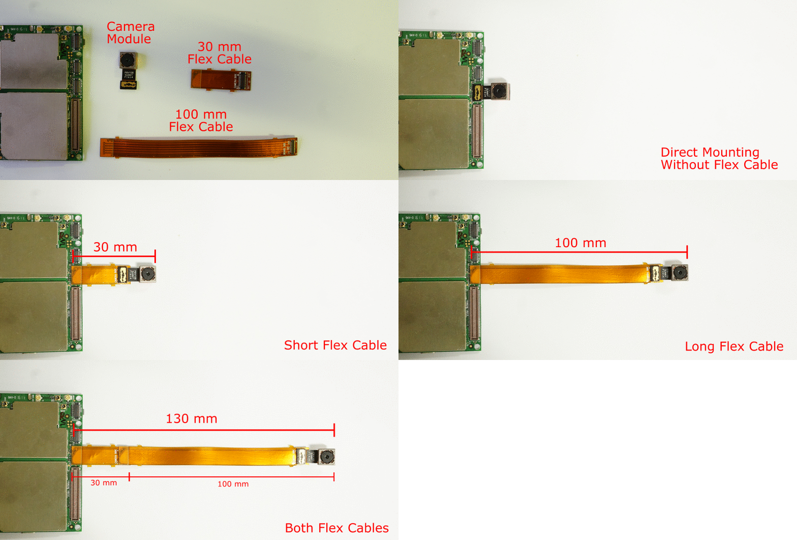
The camera connectors implemented essentially a direct plugin option for two specific camera modules we were already using. This was deemed sufficient at the time. We used an existing 8 MP camera module with autofocus support as the rear camera. The connector on the board matches the camera. The camera can plug in directly onto the board – this helps to minimize the form factor while building a phone. Sometimes, there will be a need to place the camera a further distance away from the board. For that purpose, we have flex cables of two lengths: 3 cm and 10 cm. These cables are designed so that they may be combined to achieve a longer length, if required:
![]()
The display connector was designed to be highly generic. Mobile displays are generally based on MIPI DSI, generally the only native display option on cost optimized mobile SoCs (such as the MSM8916). We routed all the MIPI DSI lines to the touch connector. The touch panel on a mobile phone is typically based on I2C, that’s two more lines. Backlight control needs a PWM signal. For audio output, we needed I2S. Finally, we added power lines and a few spare GPIOs to complete the display connector. With this design, we were sure that we could do a lot. (Our 5" phone display and HDMI display have proved that already)
In the case of antennas, the choice of connectors was straightforward – we just chose u.Fl connectors. The range of antennas supporting that connector is huge. You can also buy “pigtails” that allow connection to larger antennas that have an SMA connector.
For the WiFi/BT, and LTE antenna we chose parts from DigiKey. We made an exception for the GPS antenna – we took a few samples of DP-10 from Sanav, which they claimed at that time to be “the smallest GPS antenna in the world”.
The biggest point of discussion was the expansion connector. My initial idea was that this would include only the low speed signals (free GPIO, UART, SPI, I2C), audio signals, and the second SIM. However, given that the Kiteboard was supposed to be used for other products, it ended up becoming the kitchen sink of all signals. A large number of additional signals were routed to it – USB, SD card, DC power, system power, …. The expansion port ended up being a 120 pin dense connector.
Expansion Board
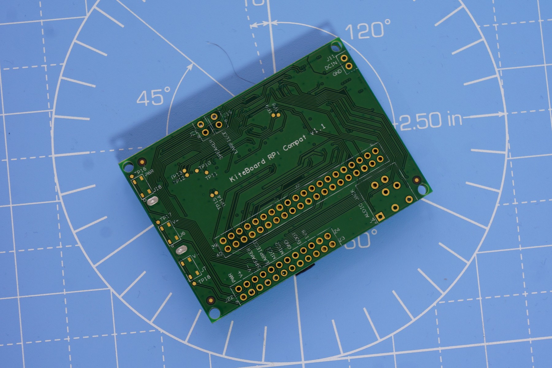
The expansion board (in its current state) was made much later than the board – it was more or less designed together with the phone enclosure. The expansion board was engineered to include a 40 pin Raspberry Pi compatible HAT connector footprint. The expansion board stacks right on top of KiteBoard. There are no components on the top side, everything is at the bottom. This helps reduce "thickness". The stacking height of the 120 pin connector is 4mm.![]()
The Pi works at 3.3V, while the KiteBoard is at 1.8V. That requires a level converter in between. The level converter allows us to select the select the “output side” voltage level. For compatibility with the Pi, we set this by default to 3.3V. However, we do have resistor options to set this to 5V, if required (very useful to make the expansion board compatible with 5V electronics used with Arduino). The level converters also implement useful ESD protection.
The expansion board also implements pads (0.1 inch spacing) for audio signals – speaker, mic, earpiece. Standard buttons (power, volume up & volume down) are also exposed on 0.1 inch spaced pads. We also threw in a footprint of an audio jack to complete the expansion board. We routed the earpiece & speaker signals to two places, to make it easier to connect these components.
To provide sufficient power at the 3.3V and 5V connectors, we included power regulators that generate the required levels & output from the system power. The enable pin for these regulators is set by the KiteBoard on boot. However, it is also possible to set these high. If this is done, then we can have the external electronics powered on always. This feature could be used to implement some very interesting things. I intend to cover this aspect in a future post – it’s an unexplored novelty of sorts!
We used off the shelf components for speaker, mic, earpiece. All these can be purchased in a single quantity from Digikey; that’s where we purchased them. The vibrator was sourced locally from hacktronics, a local online retailer for hobby electronics.
In the battery connector, we included an I2C bus. This could have come in handy, if we ended up using a battery pack which includes a fuel gauge. We already had such battery packs in other products, and it made sense to have this option.
We did not want to spend money customizing a battery, so we chose to use off-the-shelf LiPoly batteries.
To complete the kit, we sourced a nice 5” display module with an integrated touch panel. We made an intermediate display board that adapted the display connector to this display module. The display board connects to the KiteBoard using a flex cable. This flex cable can be connected end-to-end to place the display farther away if needed.
Lastly, we got a talented graduate intern to design the case…. That’s the same design that you see in the pictures & videos. To ensure that the audio components can stay in place, we sourced small connectors locally. That’s how, we ended up with Poorna, our minimal phone design.
Learning from Kite v1
We’ve now been playing with this design for more than eight months. We’ve built a lot of prototypes with it & learnt a lot. Every prototype is essentially a mini project (that takes less than a week to make, BTW)!
I have used Kite as a primary phone for over one and a half months. I found that it worked well – I could use it for a whole day, with a usage pattern that’s not centered on media consumption. That didn’t turn out a surprise to me, as I understand the power characteristics of the underlying platform quite well.
I have also noticed that the WiFi signal reception on my KitePhone is superior in many places, even when compared to a flagship phone that I use on a daily basis. The race to make everything thin certainly hasn’t come at the cost of great wireless performance in all situations… That said, it would be wise of me not to make tall claims without a thorough analysis of this! I intend to publish some results after I do a better comparison.
My primary complaint has been the RAM on the device (1GB). Switching away from Facebook to Facebook Lite solved most of these problems. However, Android does work much better with 2GB RAM than 1 GB RAM, even on Android L. Of course, we could all do with a nicer processor, among other things – which is what Kite v2 is all about!
The real revelation to me, though, has been the hardware modification aspects. When I now look back, I see that I have exceeded even my wildest expectations. Many of these builds are being documented as logs on these pages.
The intent of this post, though, is to point out the flaws. What went wrong. Here's my laundry list of what I think needs improvement:
- The expansion board is way more complex than what it should be. An ideal expansion board must be ultra-low cost, and easy to fabricate, ideally with a low-cost process (trace width 8 mil, clearance 8 mil?)
- It is would be nice if custom electronics could be swapped in & out in an easier way
- A soldering free design is a must for the base phone. This has been a common request from a lot of folks who have seen the design. I strongly agree with them!
- To achieve (1), need to simplify the expansion connector by drastically cutting down on the unnecessary signals. Somewhere in the range of 40 pins is ideal. Pin count on this connector must certainly not exceed 60.
- At-least a few pins on the expansion connector must be able to drive sufficient current for glowing an LED at a decent intensity…
- The expansion connector must not “stack” onto the KiteBoard. Preferably, it must lie in the same plane… This will help reducing the “thickness” of the phone.
- The LTE antenna needs a dedicated place. Preferably close to the speaker.
- The next version of the flex cables must not have “L” cuts. That tends to promote tearing at the junction.
- We need a good battery connector & a custom battery (in the kit). These are required for a good experience (including “soldering free base kit”) for everyone.
- The 3D design needs improvement. Not everything is as nice as it should be. To make it very easy to modify, we need it to be available as a nice parametric “solid” modifiable in FreeCAD.
How do I propose to fix these? I have most, but not all the answers. Here are some good ideas:
- Keep audio signals & buttons on the main board. Add connectors for these signals. That will take care of making this a soldering free design. For users who want to use the expansion board, it will simplify the experience of changing the hardware
- Move the 3.3V & 5V power regulator to the main board. With this additional change, the expansion board will be reduced to a “level converter only” board!
Right now, though, I don’t see a reason to spin the hardware to make these changes. We intend to do those for Kite v2 – our crowdfunded design. More details about Kite v2 are in this log entry.
Kite : Open Hardware Android Smartphone
Make & 3D print your own phone with sensors, displays, electronics, batteries and antennas. Customize Android and do exactly your thing!
 Shree Kumar