Close
0%
0%

PIXI Analog Shield

An Arduino Shield using the Maxim MAX11300 for 20 Programmable Mixed-Signal I/O with 12-Bit ADC, 12-Bit DAC, Analog Switches, and GPIO

Similar projects worth following
The Arduino Shield is called PIXI Analog Shield and puts the Maxim MAX11300 20 channel DAC/ADC/GPIO PIXI chip into an accessible form factor.
Features:
• Arduino Uno R3 compatible Shield
• Using the Maxim MAX11300 PIXI 20-port mixed-signal IC
• Up to 20 12-bit ADC Inputs, single-ended or 10 ADCs differential
• Up to 20 12-bit DAC Outputs with 25mA current capability
• Up to 20 digital GPIO
• Voltage ranges from -10v to +10V
• 60Ω Analog Switch Between Adjacent PIXI Ports
• 1 internal and 2 external temperature sensors, ±1°C accuracy
• One external sensor populated on board or connector, 2nd external sensor connector only
• One corner of the board is a break-away temperature sensor with connector
• SPI interface using the VIO voltage from Arduino connectors (5V and 3.3V compatible)
• Arduino library and demo code will be available

The initial board design was made in KiCAD, in the spirit of designing open source hardware with open source CAD tools. PCBs were build by OSHPark in their excellent quality.

I have 3 working prototype boards available, hand populated by me.

ADC input voltage ranges

  • 0V to +10V
  • 0V to +2.5V

DAC output voltage ranges

  • 0V to +10V

GPIO voltage

  • 0V to +5V input range for GPI
  • 0V to +10V output range for GPO

SPI interface using the VIO voltage from Arduino connectors (5V and 3.3V compatible, sped'ed down to 1.8V). A separate VIO regulator may be populated for standalone operation with SPI wired to a different master board like a RPI or BBB.

15V input voltage required.

The 'external' temperature sensor can snap off easily through a series of drill holes. This makes the sensor truly external and also exposes the Arduino RESET button for easy access.

Unfortunately, the Maxim chip is still not available in quantities through the regular channels. But it got featured again in Maxim's latest newsletter, so there is hope. In the meantime my 5 engineering samples are 'my precious'.

[26. Feb 2015] Things have change on the component side. Digikey and Mouser show stock of the MAXIM MAX11300 in the QFN-40 package that I used. Might be time to clean up the design and pursue a small quantity build.

Use cases for this could be monitoring multiple analog signals, driving multiple analog outputs, voltage conversion of signals, controlling brightness of up to 20 strings 3-4 LEDs each (with 25mA current). The ultimate goal will be a 20 channel voltage monitor with data capture to a PC and visualization. And I am going to attempt to build a digital Hassler Circuit. I know Bob Widlar will spin in his grave, but as long as the spining is not done by a stepper motor, he might be OK.

Currently I am working on a new revision of the board (done in Eagle CAD) to clean up the wrong footprints and change the regulator for the negative rail, to enable all IO voltage ranges. Design files will be published once the board is tested and error free.

  • 1 × Maxim MAX11300GTL Maxim PIXI PIXI, 20-Port Programmable Mixed-Signal I/O with 12-Bit ADC, 12-Bit DAC, Analog Switches, and GPIO
  • 1 × ST Micro LD1117STR 800mA Low-Dropout Adjustable Linear Regulator
  • 1 × TI LM2663M/NOPB 200mA Switched Capacitor Voltage Converter (only 6V input)
  • 1 × Fairchild MC78L05ACH 100mA Positive Voltage Regulator
  • 1 × Adam Tech ADC-028-01 Connector Barrel Jack 2.1mm SMT bought as Sparkfun PRT-12748

View all 9 components

  • MISO crosstalk

    MagicWolfi11/23/2015 at 00:08 0 comments

    I am currently testdriving a Tek scope and found one issue on the board that was undetected so far.

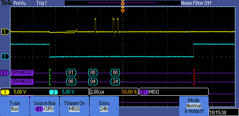
    The MISO signal picks up some cross-talk from the parallel SCK lock line during the cycle that writes the register address to the MAX11300 chip. This is how it looks on the scope.

    The amplitude of the signal is to low to cause any glitches, but a different board with a different flavor of Arduino might look differently.

    A pull-down resistor should take care of this issue and finally there is a good reason for the next revision.

  • Informational: MAX11301

    MagicWolfi08/16/2015 at 02:49 0 comments

    Maxim's PIXI, 20-Port Programmable Mixed-Signal I/O with 12-Bit ADC, 12-Bit DAC, Analog Switches, and GPIO is now available with I2C interface instead of SPI.

    PN is MAX11301.

    I imagine data transfer will be much slower, but if you don't have the pins available, I2C is always a solution.

  • Rev 03 power up

    MagicWolfi05/10/2015 at 15:33 0 comments

    The 1st board of rev 03 is assembled and works very well so far. SPI communication is established, the internal and on-board external temperature sensor are operational. And most important, the analog inputs and outputs seem to be happy. At least the ADC DAC settings with 0v to +10V voltage range.

    With the internal voltage reference and my crappy multimeter looping back the DAC value into a ADC, I see the following results:

    DACADCU[V]
    0x00000x0000-0.0039
    0x04000x03FB2.507
    0x08000x07FE5.02
    0x0B000x0BFE7.52
    0x0FFF0x0FE89.98

    Looks decent, I am just not sure yet what happens at the top end of the range.

  • Rev 03 Power rails are high...

    MagicWolfi05/03/2015 at 05:31 0 comments

    ... and low. Just finished assembly of all components required for the power rails and they look beautiful, without load that is.

    AVDD: +5.07V

    AVDDIO: +12.31V

    AVSSIO: -12.29V

  • PCB rev 03 arrived

    MagicWolfi04/26/2015 at 05:24 0 comments

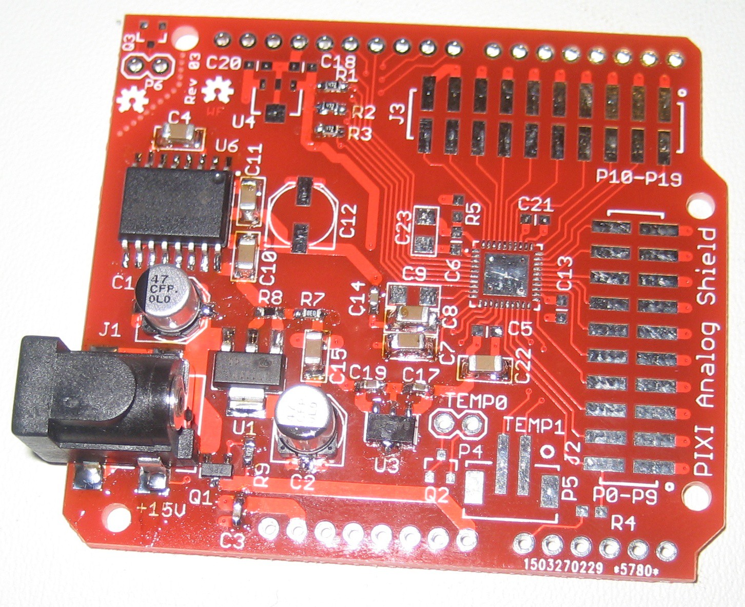
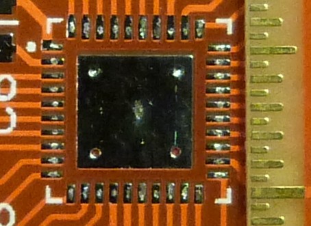
    Finally the boards from Dirty PCB arrived and they are looking sharp. I got 10 pieces and the quality is outstanding. All copper features are crisp and the silkscreen is excellent. Even 1mm text size and 0.1mm line thickness is readable. The HASL finish adds just enough material to be able to tack on components without extra solder. For full pictures see the project gallery. And here is a closeup of the QFN-48 footprint. The EEVBLOG uRuler comes in very handy to show the 0.5mm pitch.

    Can't wait until Monday when I have access to the Mantis microscope to place the MAX11300. The rest of the components is just as easy as my standard saying: "If I can see it, I can solder it".

    And who finds the mistake in the silkscreen, look at the full board? Sometimes I feel that a correct silkscreen is the hardest part of a layout. There is always one designator facing the wrong direction (not this time - it is much worse).

  • Rev 03

    MagicWolfi03/27/2015 at 03:51 0 comments

    The next revision of the board is ordered and it is Rev 03, not Rev 02 as usual. This time the design is done in Eagle and the board house of choice is really cheap and dirty (here). We'll see how the quality turns out. Design files will be released when the board turns out error free and I found the time learn how to speak github or so.

    Now the question is, what to do in the ~3 weeks until the boards arrive. Get some programming done or start a new project? I don't have a good idea for the Hackaday price 2015 yet.

    PS: Rev 02 was a board with all known issues fixed done in KiCAD, which never made it to a board house.

  • External or Internal Voltage Reference, that is the question?

    MagicWolfi02/28/2015 at 20:57 0 comments

    3 different configurations are tested to see if the internal reference voltage is good enough or if an external one is needed for best accuracy.

    For the test a LM4040-2.5 0.1% tolerance was used.

    ReferenceADC INT REFADC EXT REF DAC REF
    Internal2.4999V0
    2.4964V
    External - 10 Ohm resistors2.5033V2.4991V2.4991V
    External - no resistors2.5033V2.4991V2.4991V

    Now I output a set of values through a DAC and read the voltage level back with an ADC and compare input and output values. The voltage range for ADC and DAC are set to 0v to +10V

    Internal reference:

    DACADCU [V]
    0x00000x000-0.0070
    0x04000x04012.4920
    0x08000x08014.9919
    0x0C000x0C007.4886
    0x0FFF0x0FED9.9282

    External reference, input and output with series 10 Ohm resistor:

    Circuit for the external reference:

    DACADCU [V]
    0x00000x000-0.0041
    0x04000x03FB2.4920
    0x08000x07FE4.9983
    0x0C000x0BFE7.4976
    0x0FFF0x0FE69.9361

    External reference, input and output shorted without series Ohm resistor:

    DACADCU [V]
    0x00000x000-0.0042
    0x04000x03FD2.4970
    0x08000x07FE4.9992
    0x0C000x0C007.4990
    0x0FFF0x0FE99.9381

    The DAC does not seem to be capable of driving all the way up to the maximum value. More measurements are needed.

    Returned ADC values seem to be best with the internal reference. The external reference without series resistors has the best voltage measurements, but adding cost to the BOM. Lower voltage measurements seem to be shifted 4-12mV (2-5 LSBs) to the negative side.

  • So many LSBs

    MagicWolfi02/22/2015 at 23:48 0 comments

    Next step in the test process was to loop back a DAC value into an ADC and compare the result to the output value. The read back ADC value was in the order of 24 LSBs lower than the original output value. For example at a voltage range 0-10V a DAC value of 0x400 resulted into a output voltage of 2.4920V but the ADC value was always around 0x3e8.

    Tests with an external voltage reference and a linear regulator instead of the switched capacitor voltage converter for the negative rail did not show any improvement.

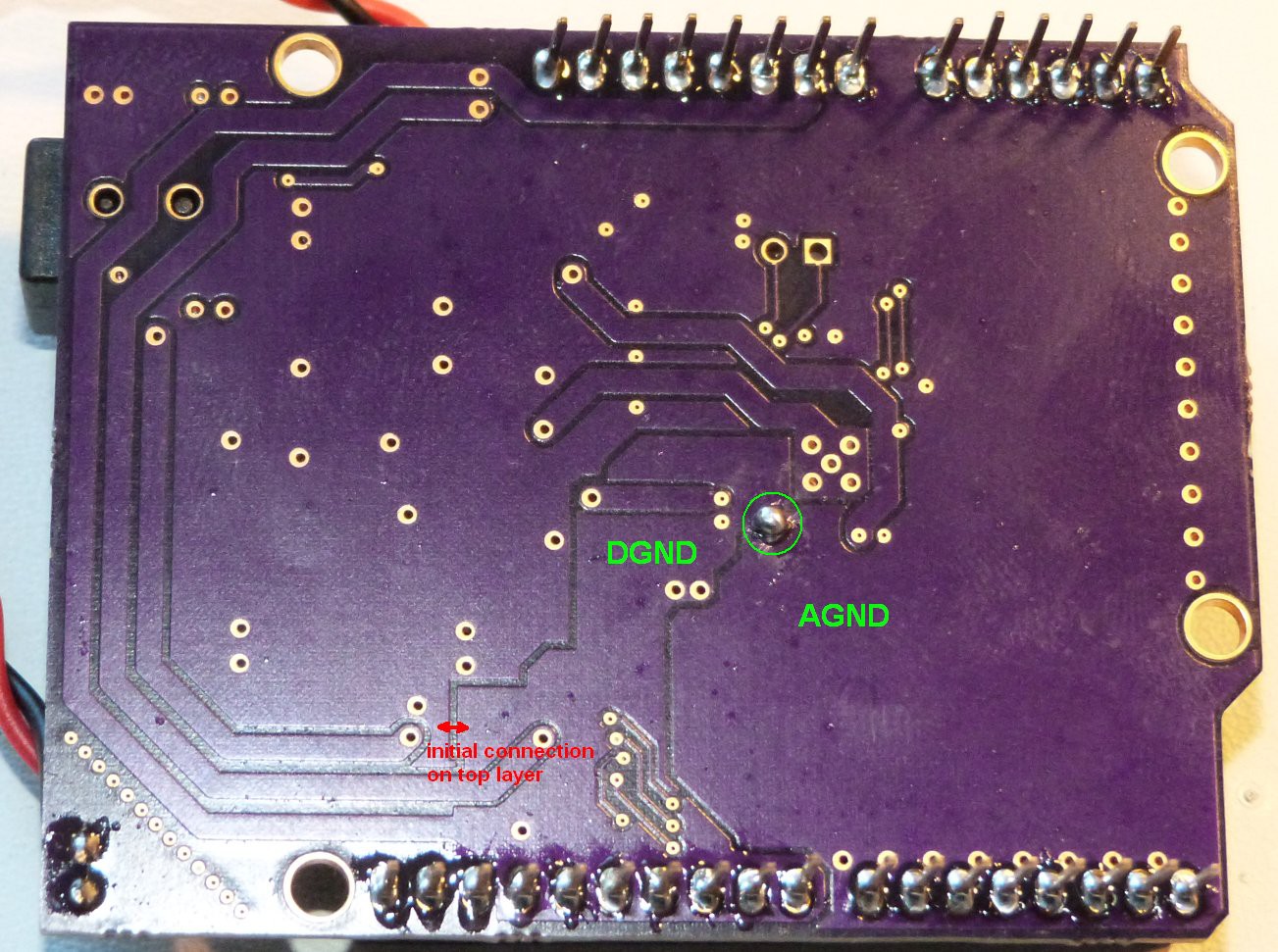
    The issue revealed itself while monitoring the analog voltage rails and SPI communication was active. During every SPI data transfer, a lot of noise was visible on the analog side. This pointed to a less than optimal GND connection point between analog and digital GND. Tying the 2 GNDs together direct under the analog IC instead of the original place close to the optional digital regulator, solved the issue.

    Now the loopback test shows a variation of 2-3 LSBs, which is a very good improvement.

  • Communication established

    MagicWolfi02/22/2015 at 00:34 0 comments

    Hooking the shield up to an Arduino and establishing communication went totally smooth until I tried to read the DEVID register. My code

    const int slaveSelectPin = 10;
    
    // Config SPI interface
    pinMode (slaveSelectPin, OUTPUT);
     digitalWrite(slaveSelectPin,HIGH);
    SPI.begin();
    SPI.setClockDivider(SPI_CLOCK_DIV2);
    SPI.setDataMode(SPI_MODE0);
    SPI.setBitOrder(MSBFIRST) ; 
    
        word result = 0;
        byte read1 = 0;
        byte read2 = 0;
      digitalWrite(slaveSelectPin,LOW);
      //  send the address and return value via SPI:
      SPI.transfer( (address << 0x01) | PIXI_READ );
      read1 = SPI.transfer(0x00);
      read2 = SPI.transfer(0x00);
    
    digitalWrite(slaveSelectPin,HIGH);
    
      result = (read1 << 8) + read2; 
    
    returned 0x0424 instead of 0x0024 as specified in the datasheet.The only reason I can think of is, that my engineering samples have a different ID to make them distinguishable from production parts.

    Everything else seems to work as documented and after setting up 1 DAC and 1 ADC I was able to output and read back analog voltages in 4096 steps in voltage ranges from 0V to +2.5V and 0V to 10V.

    Overall a promissing start.

  • Initial Power Up

    MagicWolfi02/21/2015 at 05:47 0 comments

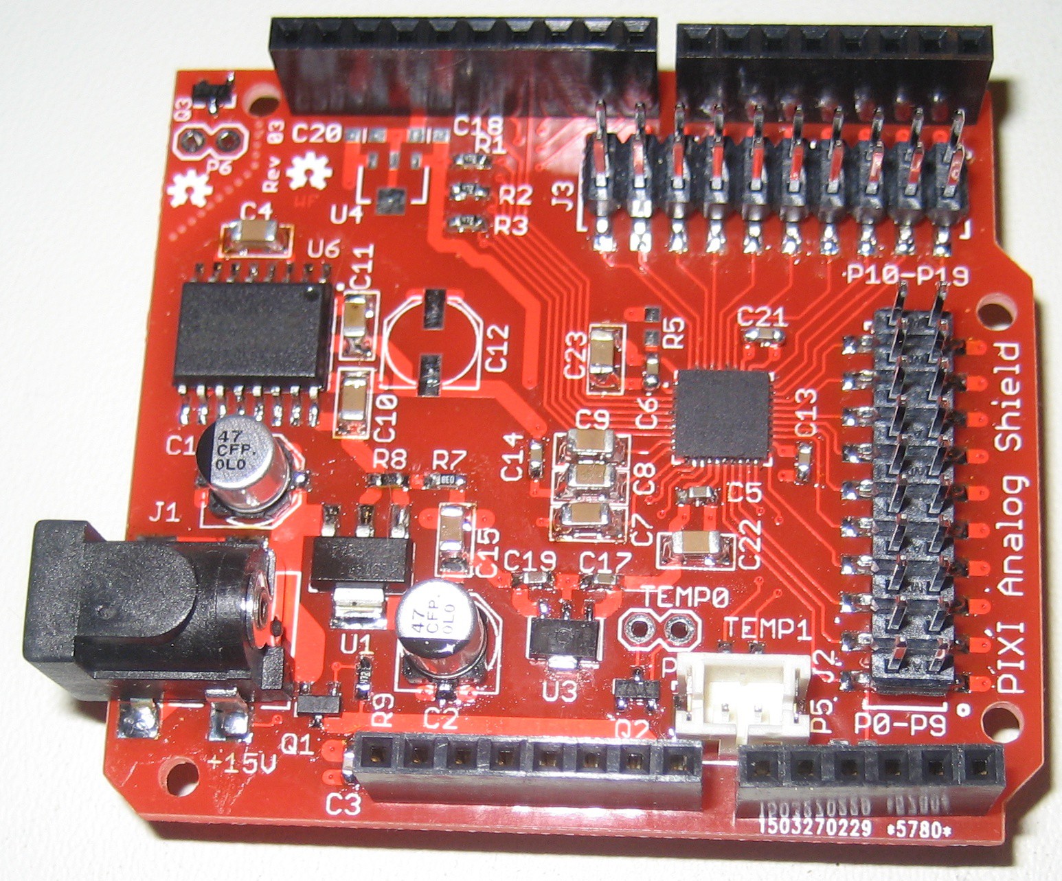
    I found 2 wrong schematic symbols, which got fixed on the rev 01 board with 1 deadbug IC and one that was not required for regular operation. The interested observer will find those fixes in the image of the board.

View all 10 project logs

Enjoy this project?

Share

Discussions

shuler wrote 08/24/2017 at 09:54 point

Hi! Great job! Is there a possibility to set range on all DACs 0-5V or 0-3.3V ?

  Are you sure? yes | no

MagicWolfi wrote 08/25/2017 at 00:57 point

Hello shuler! Unfortunately the DAC outputs are limited to the 3 voltage ranges ±5V, 0 to +10V, -10V to 0V. Your only option is using the 0 to +10V with external circuits (resistor divider or opamp driver) depending on what the output needs to drive. A daughter board plugging into the two 2x10 headers would work, maybe even a breadboard, I think I put the connectors on a 0.1" raster (if not this will be fixed on the next rev. Cheers.

  Are you sure? yes | no

jeppiot wrote 07/16/2017 at 10:06 point

What is the current state of development of your shield? It seems very suitable for a number of projects I have in mind...

  Are you sure? yes | no

MagicWolfi wrote 08/25/2017 at 00:38 point

Hello jeppiot! Sorry I totally missed you comment. The project is sitting in a cardboard box at the moment. I have working prototypes on the rev1 and rev 3 boards. I hope to have some time in October to work on the next revision, improve the driver and then build some boards and get them up for sale on Tindie. Cheers.

  Are you sure? yes | no

Shane wrote 02/27/2017 at 23:41 point

Nice job but .... would some input buffering be useful to anyone other than myself ?  I know DIP, esp socketed DIPs are archaic, but they do have their uses.  MAXIM, from recollection, tend to have fairly good immunity to "accidents".  I am interested in the project to interface to marine engines.  Coupled with an Arduino, probably a Due, and a decent sized graphical display with various analogue style gauges is my end-game.

  Are you sure? yes | no

MagicWolfi wrote 02/28/2017 at 01:42 point

Hello Shane, interesting project and ideas. Socketed input buffers are always a good idea especially in harsh environment, but would take away some flexibility here, as some IOs would be inputs only unless it can bypassed or be bi-directional analog. If you have an additional custom board you could put the buffers there

  Are you sure? yes | no

eirik.engen wrote 03/13/2016 at 20:55 point

Hi, We have a mechanical prototype that requires an actuator driven by an amplifier with analog torque input (+/- 10V). I have made a shield based on your design to do this with an arduino, but are now struggling to configure the PIXI to work on -5 to +5 V DAC, using the header and cpp library you have made. DAC works with 0 to +10 V configuration, so I hope that it is only a configuration type error that are causing the issue. Any thoughts?

  Are you sure? yes | no

MagicWolfi wrote 03/14/2016 at 22:14 point

Hello Eirik,

This is great to hear that my design is being used (should have it up for sale and save you the build time). Unfortunately I cannot do any debugging right now as I am moving across country and have no access to my boards for another 2 months at least. I will look into the code for a dry review to see if I find anything that might help. I don't even have my notebook with me and don't remember what voltage range test I did. 

Pierce Nichols with his Multispork project hosted here as well did also an Arduino library, that might be helpful for your. See my links section to get to this project. 

Hope that helps. Cheers.

- Wolfgang.

  Are you sure? yes | no

k.fetscher wrote 01/02/2016 at 15:27 point

Hello, 

why have you switched from KiCAD to Eagle ?

Regards

Klaus

  Are you sure? yes | no

MagicWolfi wrote 01/03/2016 at 05:15 point

Hello Klaus,

I was pitching this board to Sparkfun to sell it through their website and they exclusively use Eagle for design and manufacturing adjustments. So I tried to make it as easy for them as possible. Unfortunately, they did not like it. So for the next rev I am going to try the Eagle to KiCAD scripts (http://hackaday.com/2015/12/27/eagle-to-kicad-made-easy/) and might bring it up for sale on Tindie some time in the near future.

Cheers, Wolfgang.

  Are you sure? yes | no

K Kim wrote 03/13/2015 at 20:34 point

hello, I am a Senior Business Manager at Maxim Integrated and came across your design and I wanted firstly to thank you for choosing our product for your design, it looks great! If there is anything we can do to help such as provide some newer samples and source code, please drop me a message and I will get back to you.  Thanks again 

  Are you sure? yes | no

MagicWolfi wrote 03/15/2015 at 15:12 point

Hello K Kim, Thank you very much for being interested in my design. It is great to see company representatives on the 'wild' side of product development. 

I received awesome support from your Costumer Operations team with samples already. The next revision is almost finished, there will be updates. 

Cheers.

  Are you sure? yes | no

K Kim wrote 03/16/2015 at 17:13 point

That is fantastic news, look forward to the next revision.  If you need
anything for future projects please do not hesitate to ask.

  Are you sure? yes | no

Similar Projects

Does this project spark your interest?

Become a member to follow this project and never miss any updates