-
1Step 1
ESP8266 modification
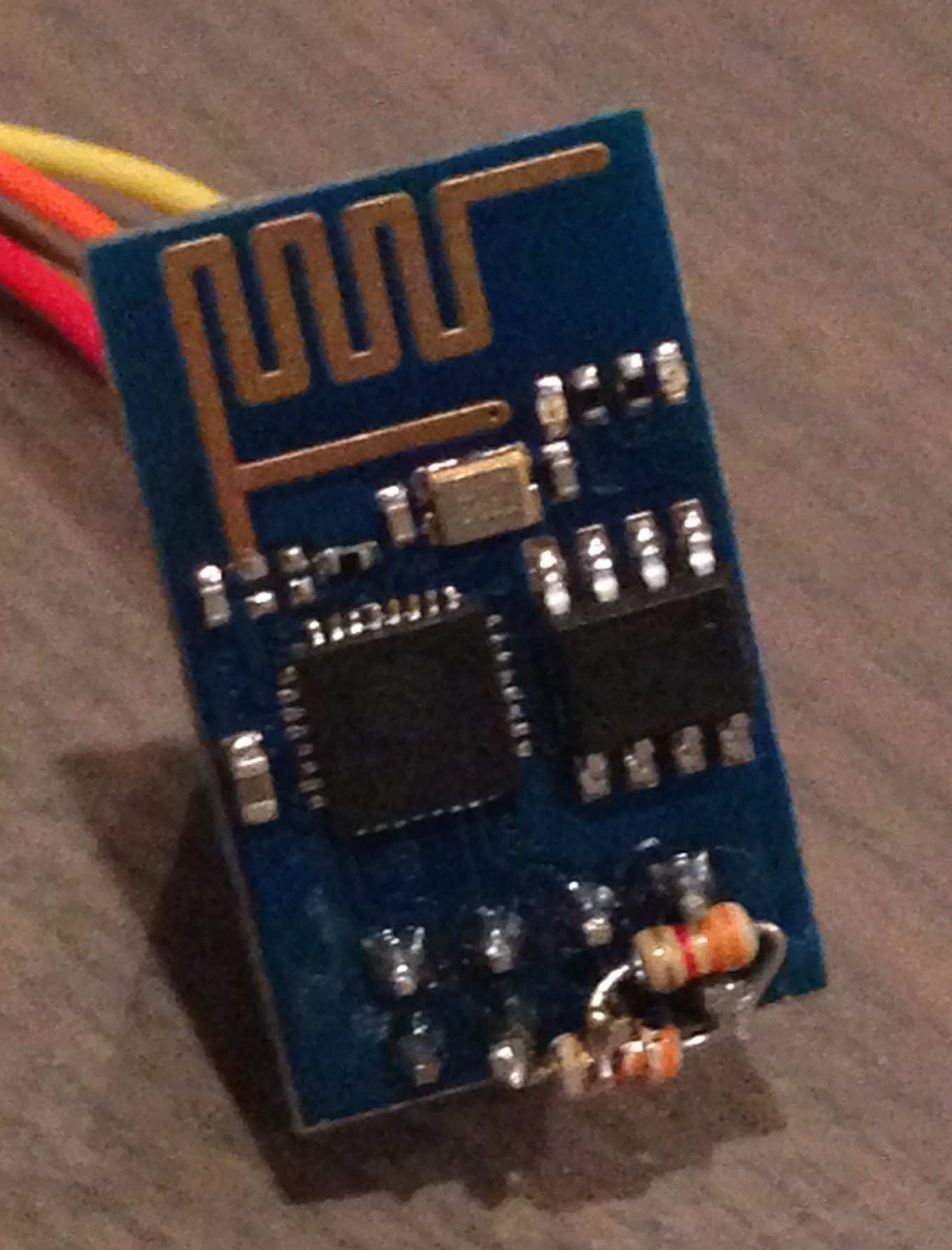
Solder 3.3kΩ resistors to ESP
![]()
Connect:
- VCC and CH_PD
- VCC and RST
Example:
-
2Step 2
Relay modification part 1/3 (voltage regulator)
Solder voltage regulator BA033. Component's pinouts:
![]()
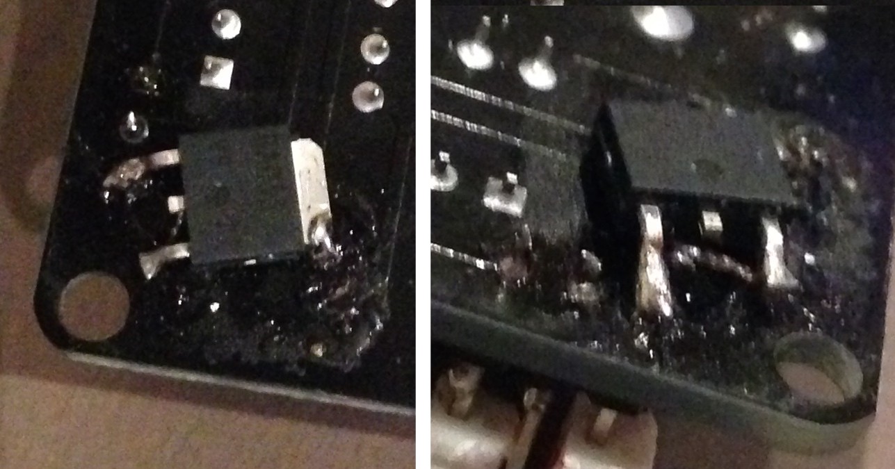
I soldered it directly to bottom of relay. Below I marked places which I used. Before soldering I scratched electronic path in places 2 and 3:
To solder pinout 2 to board you have to add piece of wire. I used wire from resistor. Result:
![]()
-
3Step 3
Relay modification part 2/3 (capacitor)
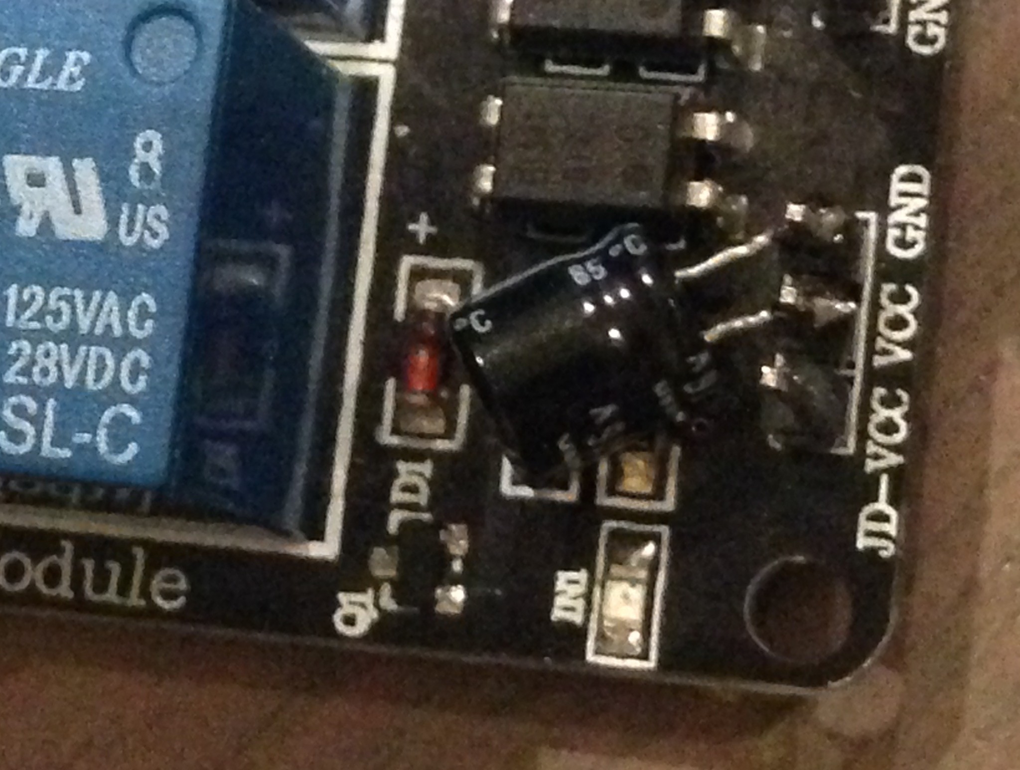
Solder at least 33uF (max. 1000uF) capacitor to pinout VCC and GND. I used 47uF capacitor.
-
4Step 4
Relay modification part 3/3 (LED removal)
I had to remove LED from relay, because GPIO current is low and LED current consumption is to high. With LEDs, relay clicking when GPIO is set to HIGH.
-
5Step 5
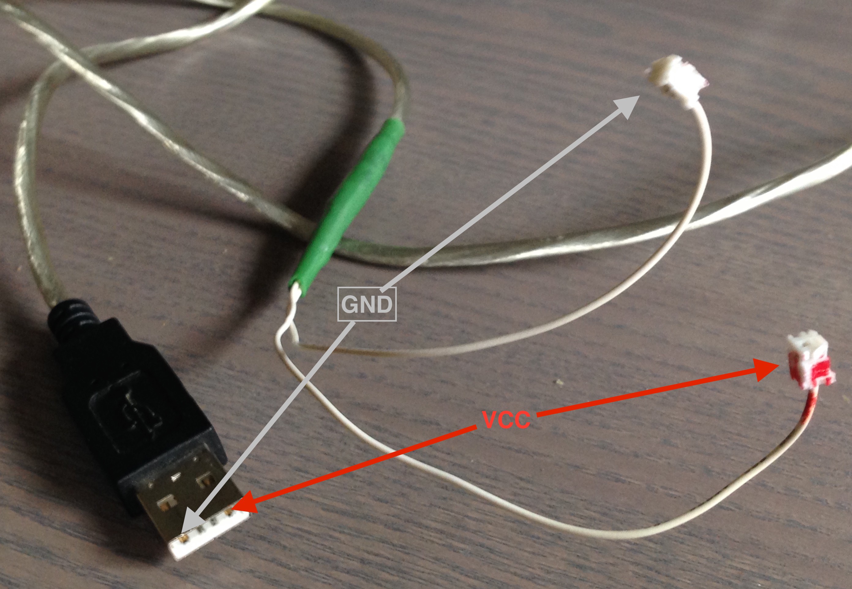
USB power cable preparation
I used a cable from old mouse, but you can any usb type cable (miniUSB, microUSB doesn't matter). Usb is only for power from any usb port. I used phone charger which cost me $1 ;-)
-
6Step 6
ESP8266 flashing
Download binaries from github: https://github.com/pawelka/esp8266/tree/master/firmware
Flash your ESP using command:
esptool.py --port /dev/tty.usbserial write_flash 0x00000 0x00000.bin 0x40000 0x40000.bin 0x12000 webpages.espfswhere /dev/tty.usbserial is usb2ttl converter location. This example is for linux & mac, but for windows will be "COM1".More informations about usb2ttl converter to ESP connection and flashing are available on page: http://taylorcoffelt.com/article/1
Some converter have 3.3V output. Those output can be connected directly to ESP.
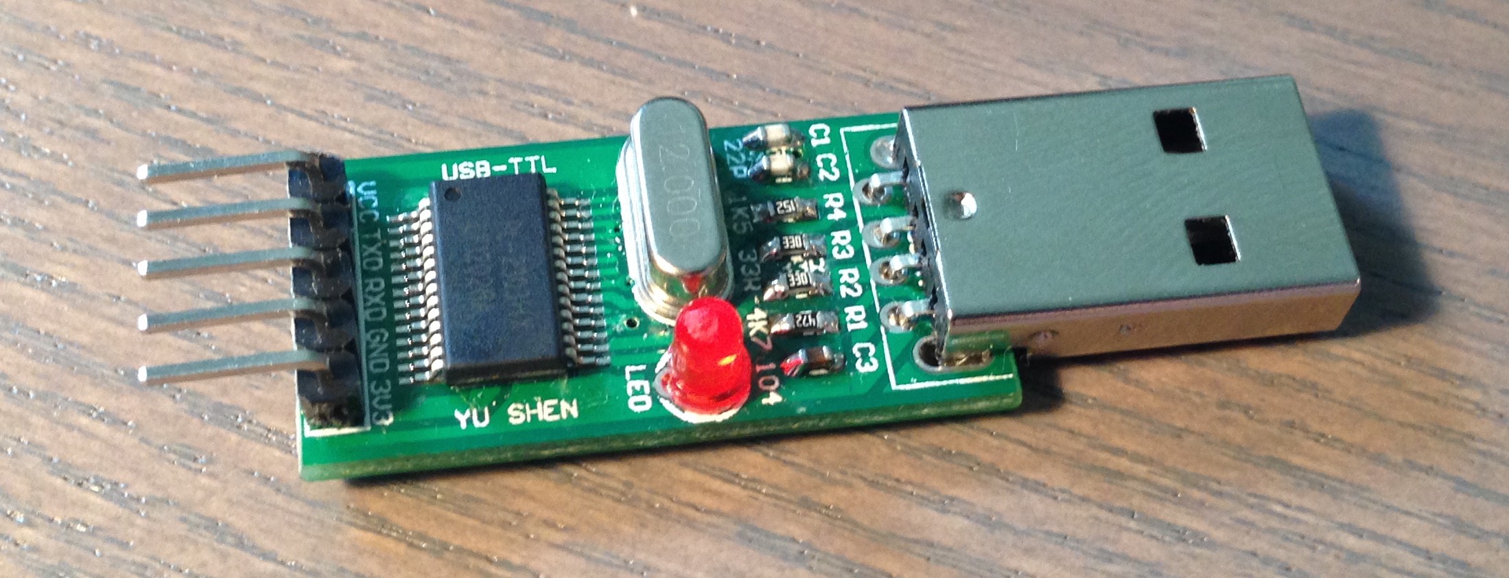
I'm using PL2303 converter, but other converters should also works.
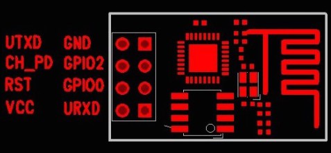
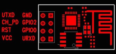
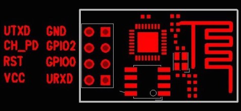
Connection:![]()
- converter 3V3 to ESP VCC
- converter GND to ESP GND
- converter TXD to ESP URXD
- converter RXD to ESP UTXD
- converter GND to ESP GPIO0 (GPIO0 LOW state on start indicate that ESP is in flashing mode)
-
7Step 7
ESP8266 with relay connections
![]()
![]()
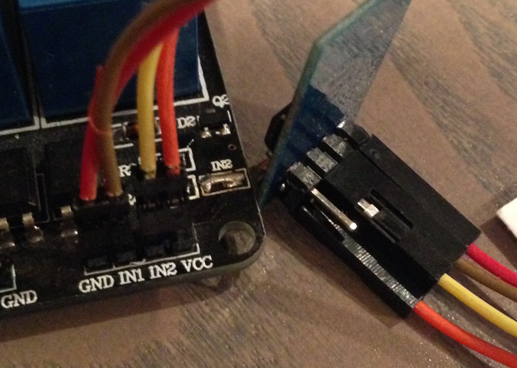
Connect:
- ESP8266 GND to relay GND
- ESP8266 VCC to relay VCC
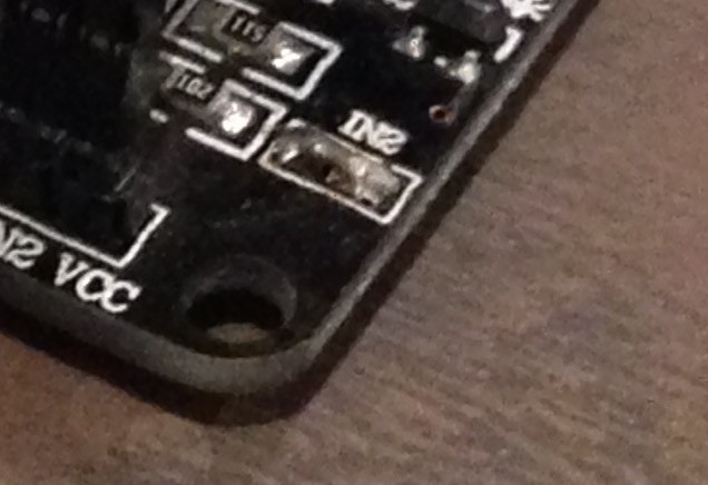
- ESP8266 GPIO0 to relay IN1
- ESP8266 GPIO2 to relay IN2
Relay power connections
Connect:
- VCC (5V) from USB to relay JD-VCC
- GND from USB to relay GND
Warning:
Don't connect 5V to VCC on relay there is 3.3V. If you connect there 5V you can burn you ESP.
-
8Step 8
Testing
Power on you switcher, after that you should see wifi network. ( screen in my native language ;-) )
Network name have prefix "ESP_", but after that can be other symbols.
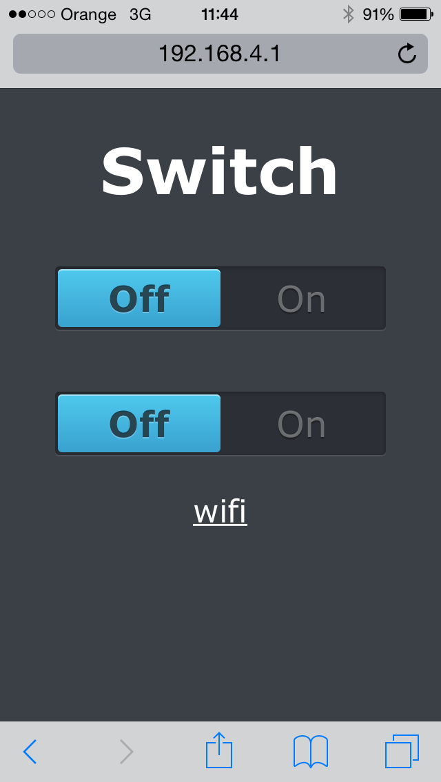
Connect to network and open page http://192.168.4.1
Now you can test your switcher.
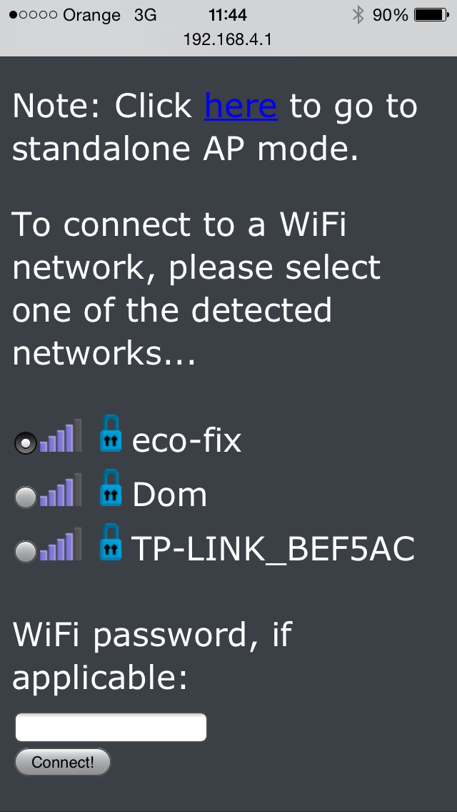
There is also wifi settings. There you can connect your ESP to your home wifi network, but at the moment there is no reset button and if you connect to wrong network, there is no easy way to reset ESP (flash standard firmware and reset settings). If I find a time, it will be next feature.
ESP8266 - native switcher
ESP8266 + 2 relay module + usb charger. As simple as possible two channels switcher controlled from web
 pawelka




Discussions
Become a Hackaday.io Member
Create an account to leave a comment. Already have an account? Log In.
Hi, I build this switch time ago, and it work well. It is my first experiment in IOT so I'm happy. The question now: can use this switch in monostable mode ( at least 1 channel) insted on/off.
Thanks
Alberto IW0HJZ
Are you sure? yes | no
Can you Upload the code of these nice looking web site :)
Are you sure? yes | no
Web site is part of the code from the beginning.
Are you sure? yes | no
great work..
Are you sure? yes | no
Paweł, I have a similar relay module (purchased on Allegro) and I just tried connecting it to a 3.3V chipkit max32 (an arduino mega clone). Relay seems to work perfectly well when powered and driven by 3.3V. Is it luck, are there any risks involved?
Are you sure? yes | no
If you don't hear clicking when relay is on, then everything works as expected. Probably your chipkit GPIO pin have better current then ESP8266.
Are you sure? yes | no
Hi,
I've downloaded the latest firmware from https://github.com/pawelka/esp8266/tree/master/firmware and uploaded it to my ESP8266. It starts up in softAP mode but I'm unable to connect because a password is required.
What is the default password? The SSID shows up as ESP8266...
Thanks
Are you sure? yes | no
Sorry for delay ;-). ESP8266 have default configuration and this configuration is not erased during flash, so password is the same as previously. Depends on vendor and ESP model default password can by different. You can use second version of firmware to reset all setting including wifi password (there will be open wifi after reset).
Are you sure? yes | no