MasterOfNull
-
Throw hardware at it.
08/25/2018 at 00:41 • 0 commentsI got on another kick of trying to design the perfect 3D printable press fit D shaft coupler.
It needs to be perfect, as error here will show up literally everywhere.
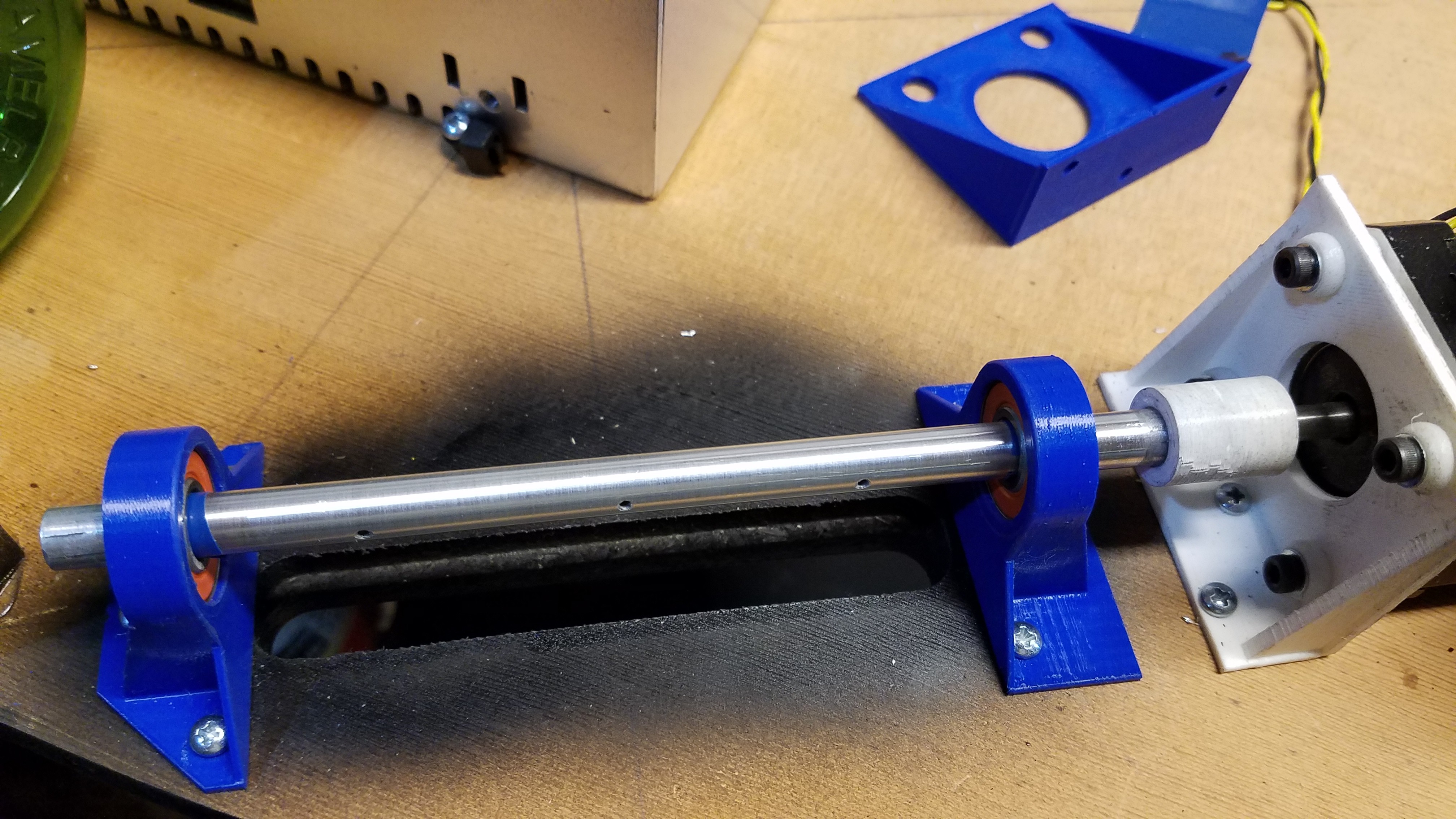
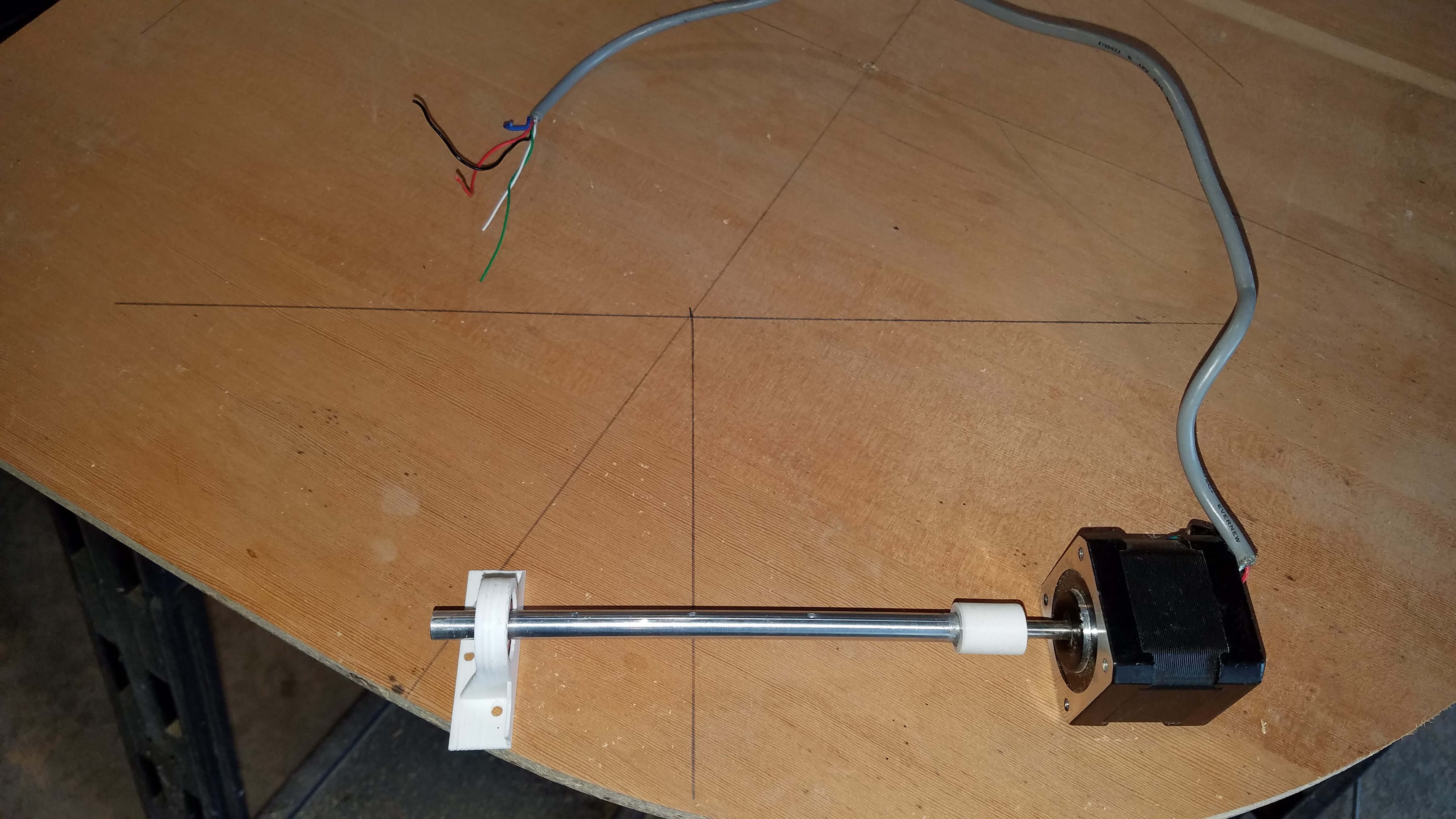
Well, a couple dozen prints later and I still couldn't zero in, so I gave up and added the second bearing block you see here. It's a better solution really.
![]()
Now my stepper is free to wobble to it's hearts content and it won't affect the accuracy of my spooling rod.
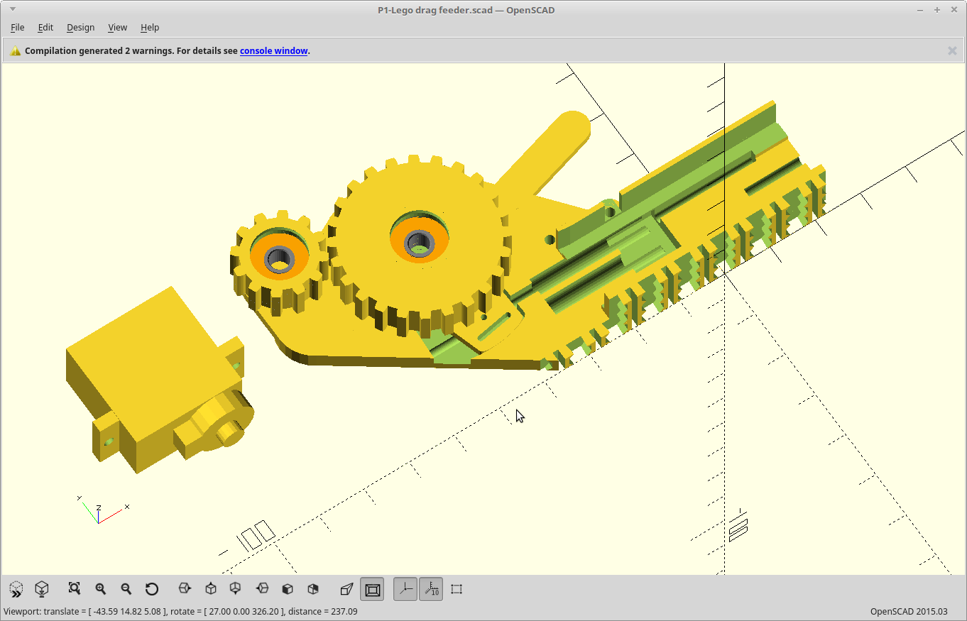
In other news, I decided the tape feeder I spent so much time on was just too tall, and started over with a new design.
Basically I took the wish list generated from the forum posts I did, and made that into a feeder.
![]()
This one is based on pinch rollers for the cover tape, uses smaller bearings, and uses a pin to advance the tape.
It also includes my Lego (compatible) base plate mounting. I'm geeked to try it, but I need to be patient.
It's tiny. 9g servo included for scale. Getting there... needs some detail work yet, like a mechanism to disengage from the tape on pull, but engage on push that doesn't involve dragging the pin across the holes. I recall one which orbited a pin and did the latter, but I can't seem to find it.
-
You can't go home again.
08/22/2018 at 19:28 • 0 commentsWell, actually I can. Homing works now.
The commands other that movement still go nowhere in Machinekit, but things are talking and moving.
I've altered the spooling rod size to be a little smaller to increase my attainable resolution. I should get about 30% better resolution now.
Overall top speed will still be in the 300mm/sec range.
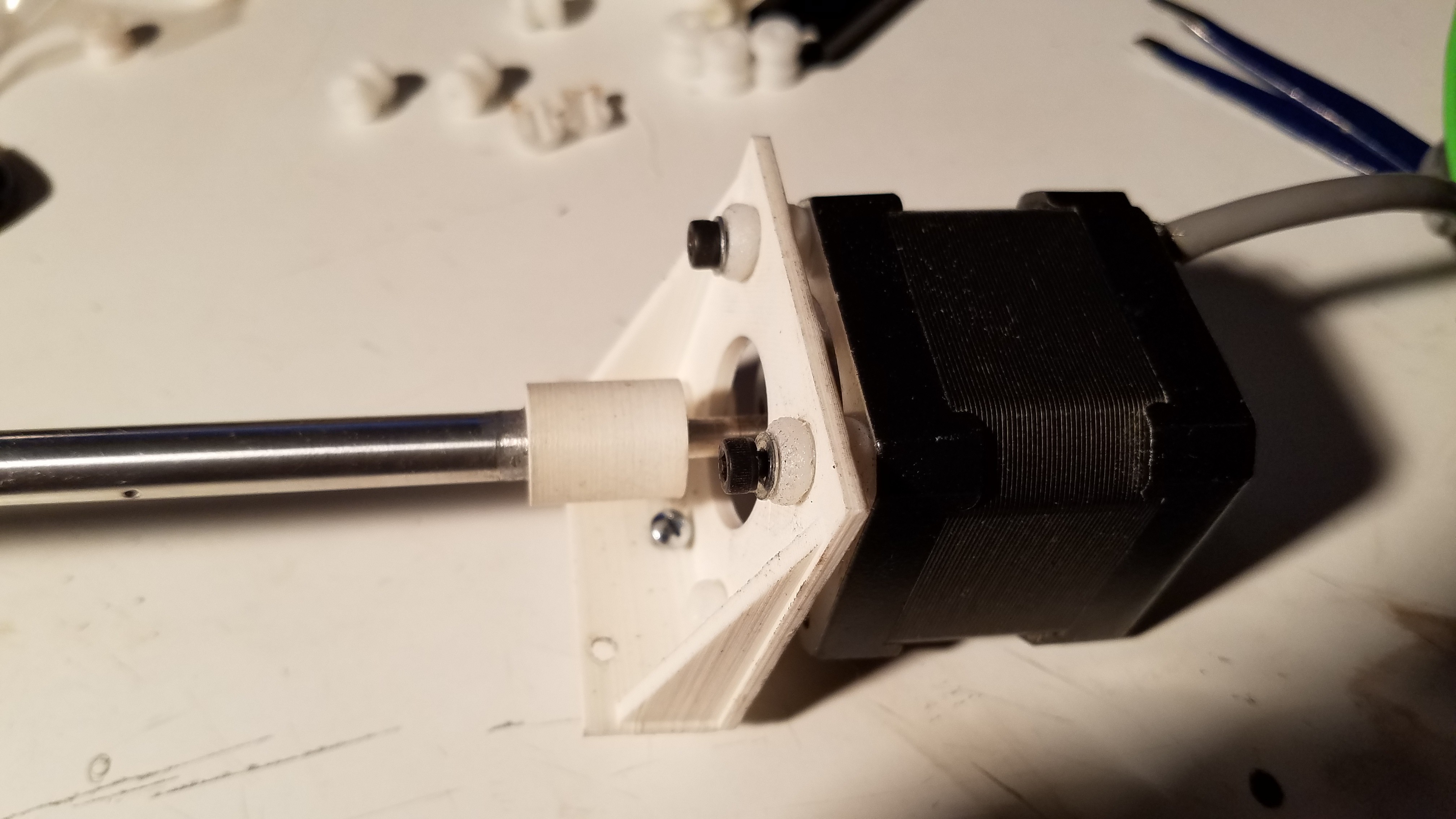
So, I have spent the last 24 hours printing versions of my coupler again to get it perfect. When I printed it before I was relying on over-extrusion, this one does not.
I scavenged a vacuum sensor from a friends teardown of an ink cartridge filling machine. 5v, 0 to -100kpa, analog out, but preamplified. I'll need to divide that down to feed it to the BBG's max ADC voltage of 1.8v. Should be pretty simple, except it needs some support caps I need to find.
Machinekoder may be able to help me out with "turning an RC servo into an axis" code as I'm running short on time. I got injured and lost a day with a trip to the doctor, and much of the rest of the day to being a little out of it.
It's probably going to be a long night.
I hope to test the whole thing tomorrow, boards and all. It will be a steep learning curve so who knows how far we will get... but here we go.. :)
EDIT: Well it just got longer. I've decided to add a second bearing block to each stepper to eliminate needing to precisely align the spooling rod to the stepper shaft. Any wobble here would translate into the entire build area being screwy, so it's kinda important and eliminating it has been challenging. Even after I had it perfect, upon installation it was screwy again. This will work better in the long run and will be a lot easier for everyone else to replicate.
Printing.
-
Build it, and they will come.
08/20/2018 at 00:44 • 0 commentsThe last two days have been spent building and configuring OpenPNP on the Pi.
It's java, but uses native code for the camera interface, which wasn't setup to be built for armv8, or any arm for that matter. With some help of the forum, they got me going.
That part is working now, but my camera is not showing up in their dropdown. I assume it's still looking for USB cameras and I need to configure that somewhere.
Working on it.
EDIT: Nope, my fault. I had turned down the GPU reserved memory too much, and the v4l2 kernel driver wouldn't load. I put it back to gpu=128 for now and I have /dev/video0 again.
After doing this the device shows up in openpnp, and the light comes on when I select it.
However, the formats menu is goofy with all resolutions and framerates being 0. I also get an error on startup of
queryFrameSize returned non-discrete frame size!
14 times. That matches the number of formats available. I believe there is some miscommunication occuring in the v4l2 implementation which needs to be corrected.
In other news, the LinuxCNC driver is working, sorta. Connected, but the homing sequence openpnp comes with is silly and doesn't actually do homing at all. I'm making it actually home the machine.
Working on it.
EDIT 2: It works. v4l2 was providing some inaccurate responses for the camera capabilities. I just hard coded the responses that should have been happening into the capture driver, and I have video.
The LinuxCNC driver still fails to home the machine. I'm missing something. Working on it..
-
Too many keyboards..
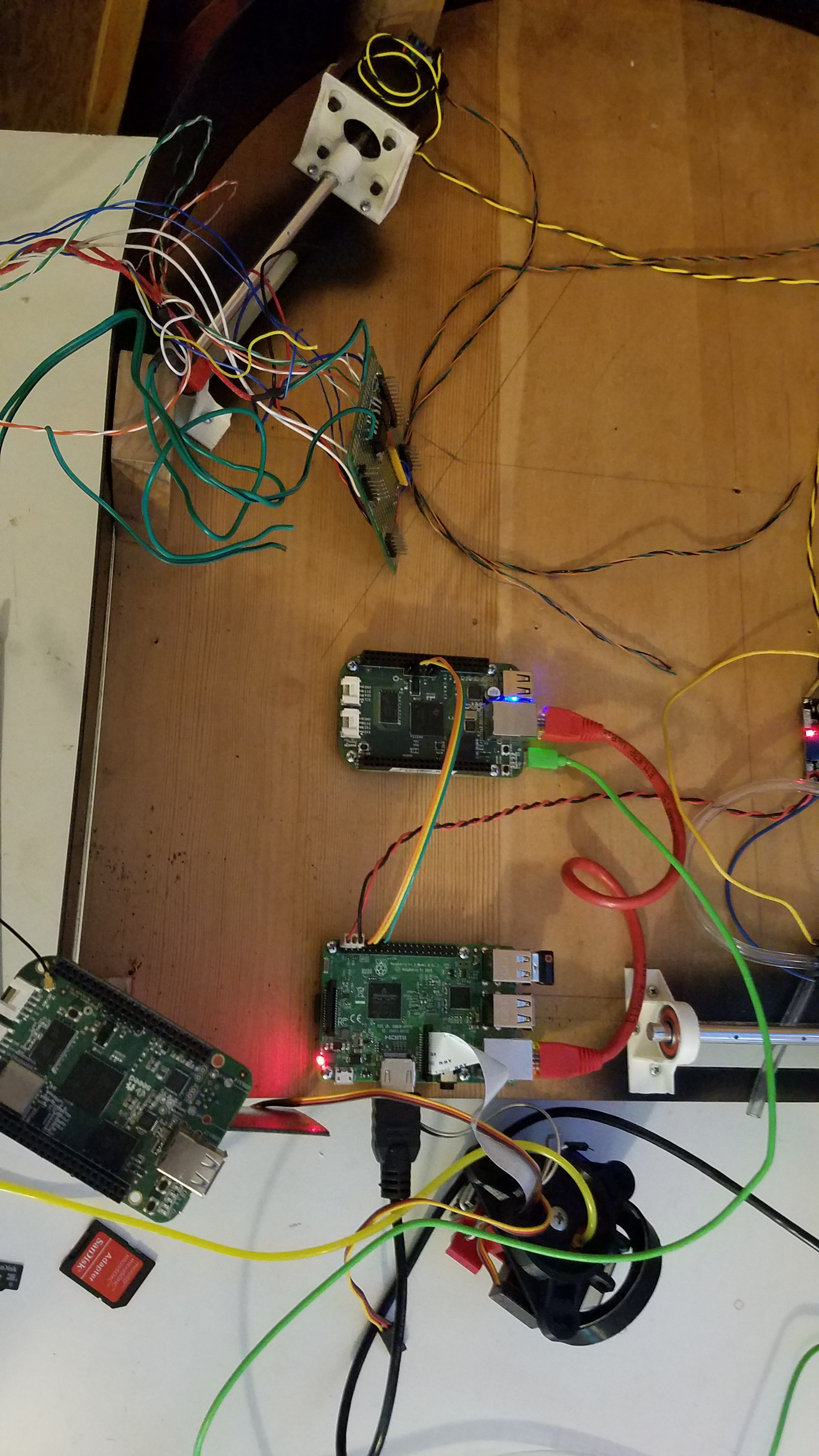
08/15/2018 at 18:22 • 0 commentsThe Pi and BBG are mounted, OS installed, and I've connected them with serial and ethernet.
The camera for the latest printed PNP head was tested and works well! I'm very happy with the full resolution zero latency captures I can get from it.
I've also transferred my configs from the C1/E1 as most of it will be useful and give me a head start.
![]()
I find myself on the wrong keyboard now far too often.
Openpnp wants to download stuff, which I can't let happen yet. Thursday.
-
Trivial Idea...
08/14/2018 at 22:30 • 0 commentsHaving two boards running two operating systems with one being basically the slave of the the other got me thinking.
I think it would be rather convenient if the Beaglebone actually booted from the Pi, via TFTP. One image loaded onto just the Pi could then be used to manage both.
Beyond the initial boot, I'm envisioning it also mounting things from the Pi via NFS.
I went looking and setting up the Beaglebone to do this is possible, and does not look too hard. There is still the matter of both boards coming up at the same time so the Beaglebone will be looking for the boot image before the Pi OS has begun to start. I don't know if/how long it will wait, if it will retry the operation, or if it can be configured to perhaps sleep during uBoot to wait for the Pi to start it's TFTP server.
If not, I suppose I could always have the Pi hit the reset button on the Beaglebone as part of its startup.
I'll just have to try it and see. Probably not now as I'm trying to avoid any more feature creep until 'Make it work first' is a reality.
-
Make it work first..
08/14/2018 at 11:27 • 0 commentsThere are a number of ways forward with regards to what is going to live under the Raspberry Pi, but all of them have a current, active roadblock except for one.
I'm going to use both a Beaglebone Green and the Raspberry Pi for now. Comparing the eventual additional hardware costs given the low IO count, lack of an ADC, and only one (or two) hardware PWM pins available on the Pi, I think I might actually leave it that way. There are two things which could still happen to change my mind, but I'll elaborate on those later.
Basically I want the smoother acceleration and ease-of-use that Machinekit gives me, but I also wanted to be able to run everything on the Pi. Software-based step generation does work, but not at the high data rate that I'm going to need to take advantage of how insanely low the mass of what my steppers need to throw around is.
If I can run the step generation at a higher step rate, I can then use the micro stepping of the drivers at a higher level. Since the static load (the force trying to pull them one direction, in this case, gravity) on my steppers is so low, more microstepping may actually be somewhat accurate. Accurate microstepping means I could run a slightly larger spool diameter and go faster. I'm not going to do that though as having the extra accuracy will allow me to push the edge of the build envelope out a little bit instead.
With the tripod kinematics, achievable accuracy is directly related to your current position. As you approach any cable, you start to trade accuracy in one dimension for accuracy in another. The best balance of vertical/horizontal accuracy happens to be right were the boards for assembly are ending up, but where the feeders will be does trade some vertical accuracy for horizontal accuracy. Having the extra steps, and if microstepping has a low enough load, the extra accuracy, will be useful and give me more breathing room there.
Moving the trajectory planning and step generation to the Beaglebone lets me use the PRU and therefore generate very accurate step trains at AM radio frequencies.. aka.. whatever rate I want. That's, way, way faster than the driver chips could possibly go.
So the end result is I'm going to have two computers in there but that's fine, as the cost is about the same as adding all the little bits i would need to add without having it. The Beaglebone can deliver them all and then some.
Decision made, I wired up the Pi and Beaglebone, steppers, basically everything I'm ready to mount yesterday. I'll post some pictures later.
-
TPU vibration isolators.
08/12/2018 at 02:49 • 0 commentsSpent some time refining the model for the 3D printed vibration isolators today. It's a lot easier to print now.
I cut one of the failures in half so you can see what it looks like on the inside.
![]()
They fit in the oversize mounting holes on my stepper mount.
![]()
Sliced in Cura set to 1 wall, 2 top/bottom layers, no infill, and over extruded by 20%
I fit all the parts for the base today, then disassembled it again. The second coat of lacquer is drying now.
Assembly tomorrow.
EDIT: A day later, and the paint is still too soft to work with it.
-
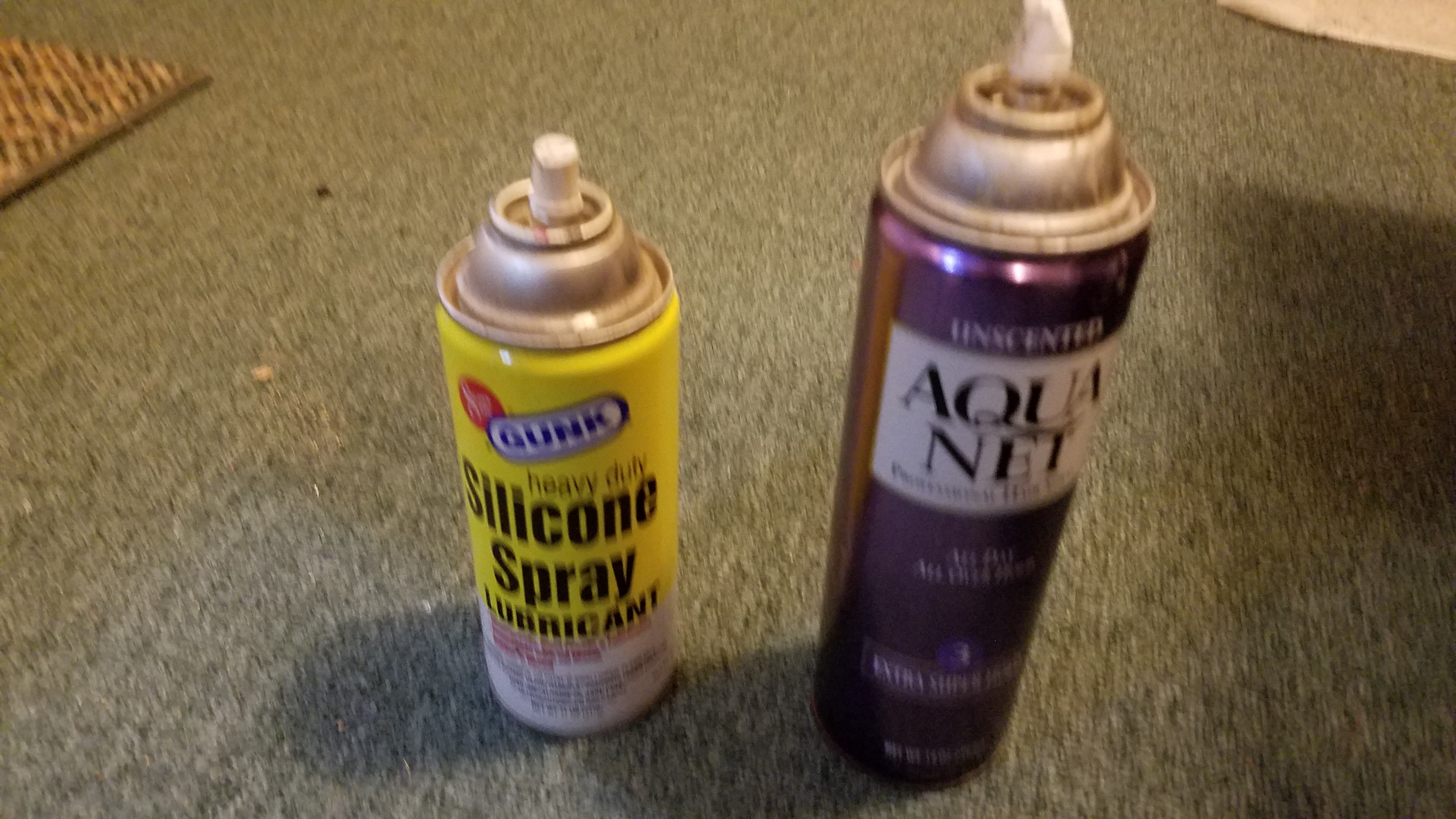
Silicone, sucks.
08/11/2018 at 09:43 • 0 commentsGiven the choice of placing your can of silicone lubricant you use to clean and lubricate the balls and pushrods on your printer next to it, in the same general area as your hairspray, don't.... ever.... do.... that.
![]()
I grabbed the silicone instead of my hairspray and started to spray my bed... for a split second, once.... for one part... and have been paying for it ever since.
I've now lost 4 prints due to adhesion issues, which basically never... ever.... happens for me.
The silicone has seemed to sink into my granite bed rather readily, and so my stupid mistake has been very difficult to eradicate.
Bah.
Another round of razor scraping and acetone, and...
Printing... again.
-
Wood-working, Take 2.
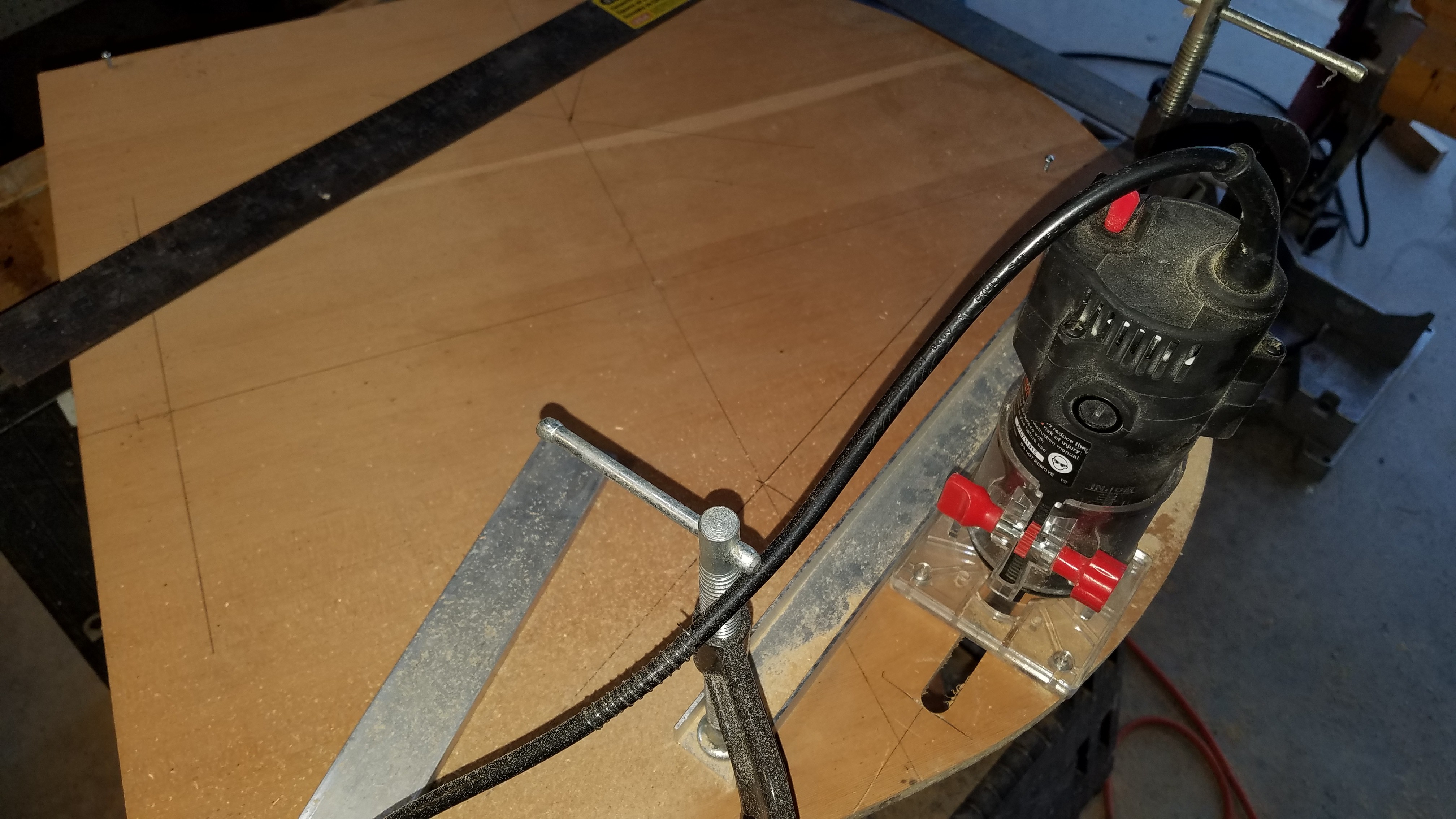
08/11/2018 at 01:43 • 0 commentsSince I finally have my rod positioning settled again, I could move on to building the base.
Routed out a circle on one end of my 2'x2' piece of oak laminated particle board. I'm going to wrap the outer edge in a strip of polycarbonate I have leftover here from building the M2 and paint the inside black, assuming I can remember what paint chemistry does not break down polycarbonate.. Feel free to comment!
It's going to be pretty, and simple to do to boot.
![]()
The new lower mounts eliminate the crossmember, so I modeled a few 3D printed templates to avoid having to measure stuff.
![]()
Figured out where I should put my drive rods. Basically I moved them out as far as I could staying parallel to my top pulleys, and still keeping the mechanics hidden. Yes, I'll cut the edge off.
![]()
Routed out the slots for the 'cables', roughly accounting for the angle at which they will intersect the upper pulleys.
![]()
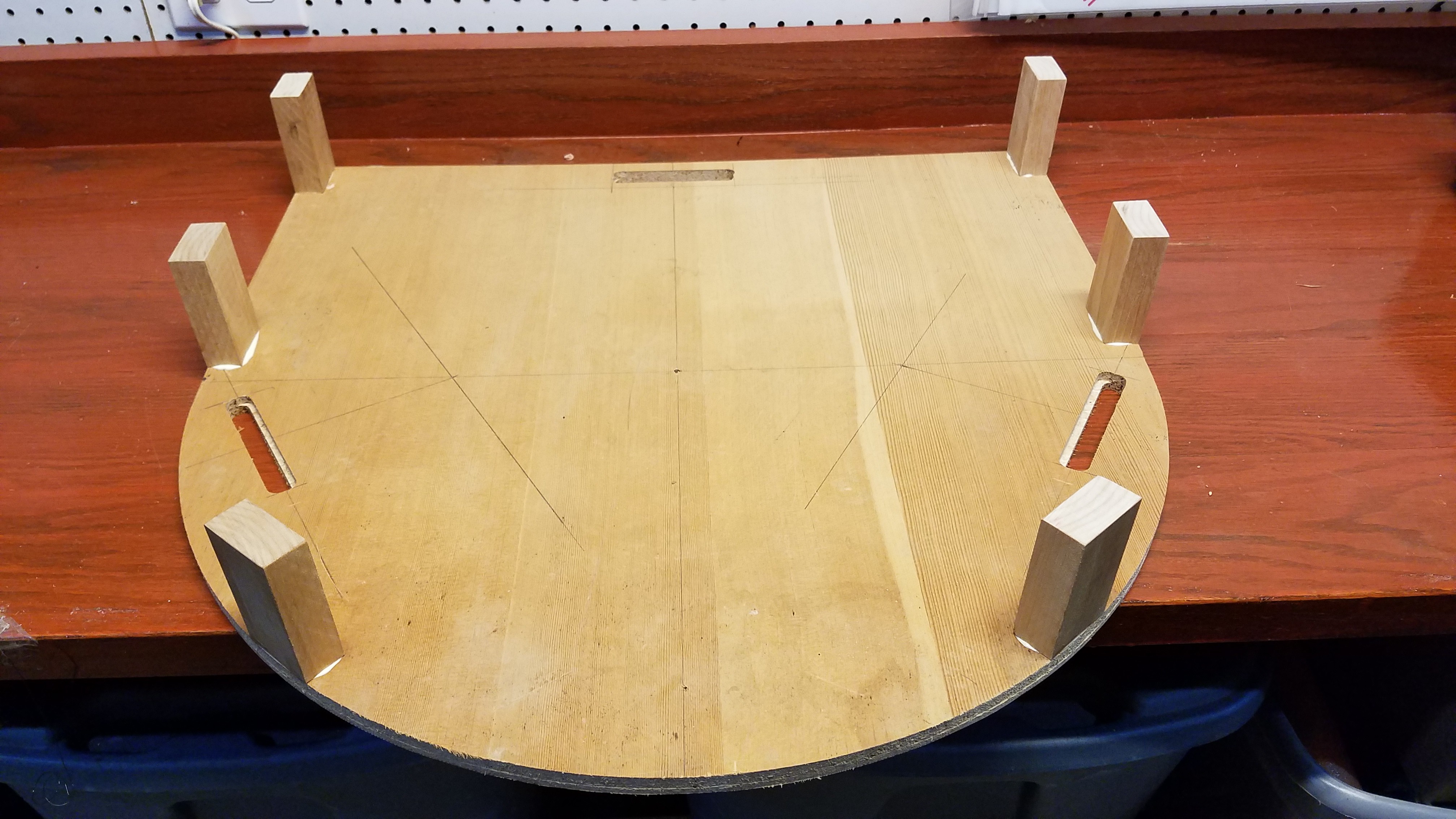
Added the blocks which will support the plywood base, and allow me to fasten down the polycarbonate strip. Yay, I got to use my oak blocks after all...
![]()
Waiting for the glue to dry overnight, then I can assemble it.
![]()
-
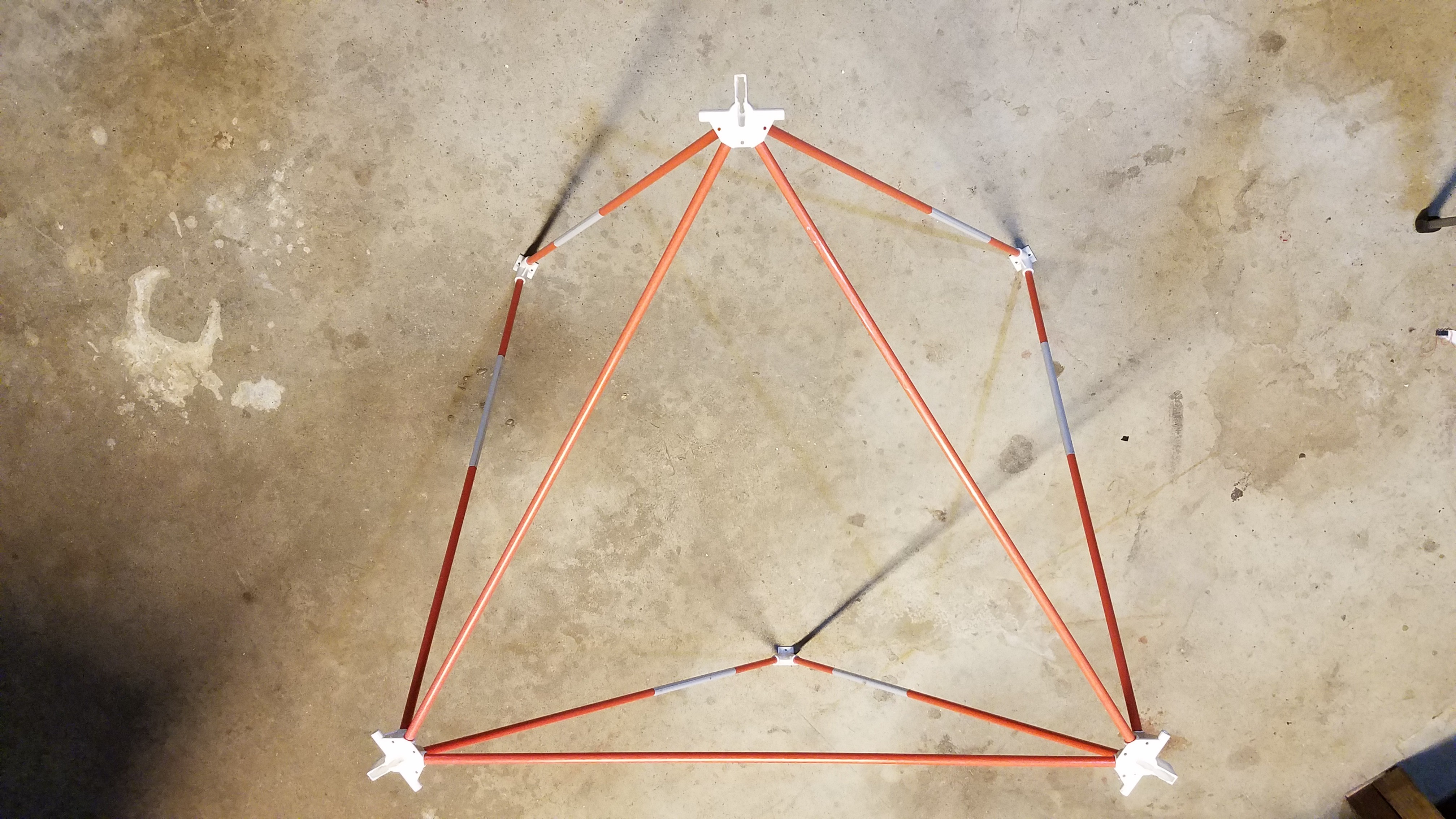
Fail.
08/10/2018 at 18:21 • 0 commentsI assembled it.
It doesn't even come close to the stability I had with the original equal length octahedral frame.
I'm calling this a fail, going back to the original design, and moving on. I'm still moving the steppers out and under the board though.
Arcus-3D-P1 - Pick and Place for 3D printers
Open source, mostly 3D printable, lightweight pick and place head for a standard groove mount