MasterOfNull
-
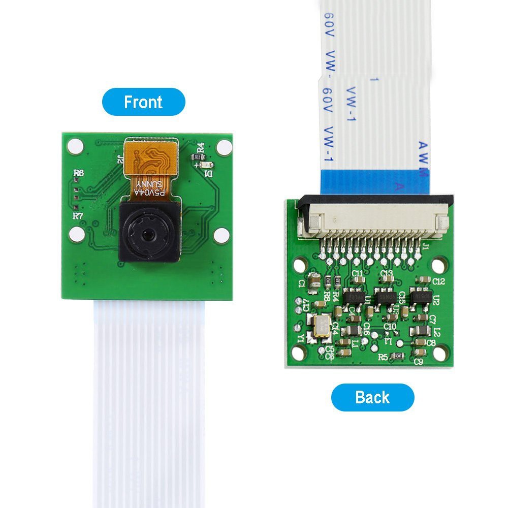
Goodbye endoscope, hello Pi mini camera.
02/27/2018 at 02:45 • 5 commentsI've settled on this camera. FOV is narrower (which is a good thing) than the newer Sony chip based ones, and it's cheaper.
![]()
"Mini" is still big enough to really mess with my setup though if I mounted it as intended. It would intersect my mirror arm mounts, the path for the mirror arm linkage, and my new adjustable stops.
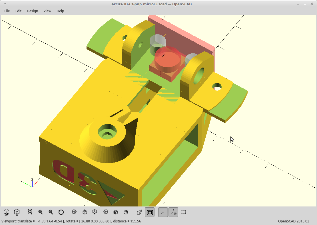
Instead of making everything bigger/heavier here is the new plan:
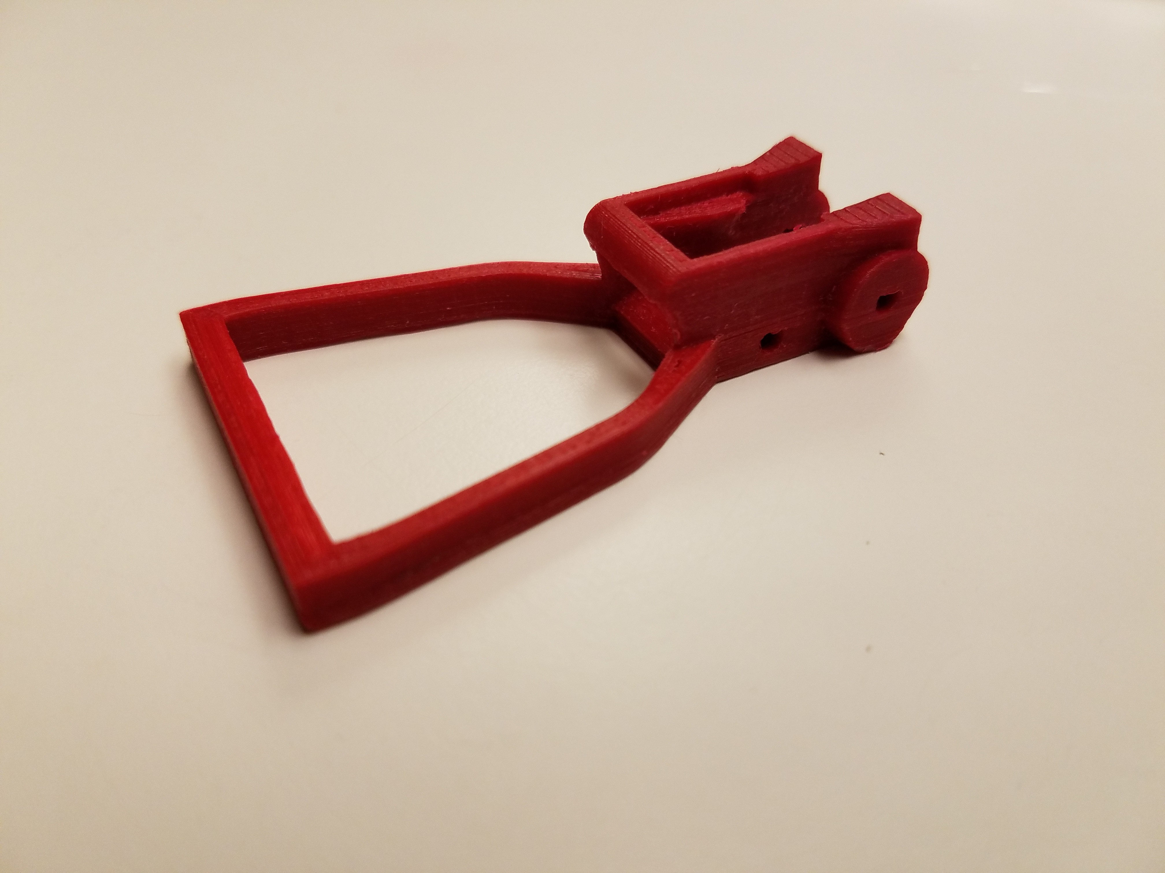
![]()
I'll mount the PCB on the side and use the little flex cable attachment thingy on the camera itself to put the new camera basically where my old one was.
It still needs height adjustment, some more screw holes, and a little more clearance, but the rest of the design should mostly work like it is 3D printed bits wise. I can even keep the endoscope mount if someone finds a suitable inexpensive one with exposure control.
Electronics wise... radical departure time.
I had a couple Pi Zeros here just begging for a new project to consume them and I almost listened. The fact I could put the entire vision engine on the head and feed it just power was tempting, but alas logic won out.
The Raspberry Pi 3 gives me 4 cores and more memory and I really liked the idea of having a dedicated core available for each high processor usage task. So I got one core for OpenPnP itself and it's piggy JVM, one for OpenCV and it's (albeit simple here) neural network hungry nature, one for the unknown variable here... klipper, and one for the OS to keep the data moving around efficiently. The fact I get direct access to uncompressed images without delay and have enough resolution and speed to implement digital zoom went a long way too.
Trying to fit all that on a Zero made me uncomfortable and I haven't even built it yet!
I will probably just feed Machinekit for now though as writing new kinematics for klipper looks more than trivial, but I think the best path for everyone (except me) would be driving your existing Arduino hardware that way. I even ordered a RAMPS 1.4 board. I've been building printers for years now, and I'm proud to say that this will be the first Arduino based interface board that I actually didn't build myself on some perf board. The knock-off boards are down to $7 and that will save a lot of time.
I could be wrong about the Zero, but I'm probably right. Prove me wrong later.
So that's the plan, and the parts will arrive tomorrow.
I've been totally ruined by Prime.
EDIT: All the parts are here. It's been 12 hours... Yep. I'm ruined.
-
Scrapping the endoscope, and all that means.
02/24/2018 at 21:45 • 3 commentsI've been mulling over ditching the endoscope for a more mainstream camera module.
The S/N ratio sucks, the quality sucks, and I have no control over exposure on the one I have. The exposure is a big deal as when I switch from bottom to top vision, the brightness changes which causes a delay until it adjusts... every time. It also has started to intermittently fail, like the imaging portion is losing bits. This is probably due to the sheer number of times I've had to mess with it as the USB cable also had an issue at the attachment point.
So I've been researching replacement cameras. The statistics for the other USB endoscope cameras have been really hard to pull together and determining if any of them supported control over exposure has been... impossible. I think I'm going to go with a more mainstream camera.
I've settled on either the Raspberry Pi mini camera version 1.3, or the ELP super mini 720P 45 degree version. Both would fit my current design with some modifications..
The ELP has a little larger footprint at 26mm square, and the camera is centered on it, which would cause an issue with my current layout as the mirror arm linkage passes through that space. However it would plug right in where my endoscope was going into the current plans of using the BBG as my platform.
The other plan using the Pi mini camera is a radical departure from 'the plan'.
Obviously this requires me to move my vision processing to a Raspberry Pi. However, the Pi would actually be faster at vision, and the entire image pipeline is much faster as well since it doesn't have to traverse the USB bus. But the Pi can't do step generation with hardware real-time accuracy like the BBG can using the PRU on Machinekit so I lose the ability to have a single board solution. I'm also partial to kinematics other than cartesian for which there wasn't really a good inexpensive solution, until recently.
Through the use of klipper and a couple cheap arduinos I get the best of both worlds, mostly. The arduinos (yes, you can use more than one synchronized) handle the hard real-time stuff and are just passed a queue of things to do, whereas the motion planning and actual interpretation of gcode happens in python on the Pi. That is a step up from the old way of trying to squeeze the motion onto an 8 bit AVR with varying levels of compromise required.
The downsides of switching to klipper:
- No S-curve motion planning, just trapezoidal.
- I would need to write the kinematics module I need from scratch, but at least I could do it in Python.
- There is an inherent delay from when you issue a command to when it executes due to the queuing which needs to happen on the arduinos.
- It's brand new and still experimental, whereas Machinekit has been rock solid and I've used it for... years.
- Hardware changes, as my current solution uses a custom cape plugged into a BBG.
The upside:
- I could use a standard, cheap, RAMPS board and get basically the performance of a Smoothie board.
- Faster vision with a better, widely tested, and well documented camera checking all the boxes.
- More cores on the Pi, for less contention for when vision starts to suck down the processor.
- Possibly hardware accelerated OpenCV performance via the GPU?
I'm mulling it over.
If you made it this far, feel free to weigh in.
-
And now stop..
02/22/2018 at 23:34 • 0 commentsI'm switching to an adjustable stop for the mirror arm.
I've printed a couple mirror arms and scraping each one for final adjustment of the angle is getting old.
I figured out how/where I could put the adjustment screws without adding weight to my arm. Of course this means reprinting everything.
Doing that now.
-
Ring light, or light ring..
02/21/2018 at 18:11 • 0 commentsI printed the light ring. That's what I'm going with.
It was too small because I modeled the strip length based on the outer surface, I'm actually using the inner surface, so.. the strip is too long and doesn't fit. It's important that the strip goes all the way to the end in my ring as I'm already down ~2 LEDs and about 70 degrees from the gap required to clear the arm.
Instead of reworking the model math to fix my error, I just added a negative offset to the variable which held my end clearance to match how much more length I needed.
I also tested the mounting slots, fitting them to my newly printed mounting arm wings. The light ring split along the layer lines fairly easily. I made that area thicker, wider, and taller in the model, so my weight is now up to 1.3 grams.
Mounting the tabs into a channel on the surface with super glue instead of modeling a proper socket would probably work better here and was actually the original plan until I got going on the idea of a socket.
I reprinted the ring with the length and socket changes.
![]()
The strip length is right now, and the socket is strong enough, but it is a real pain to clean up. Short ledges right next to short bridges doesn't work so well. I was thinking about going back to the surface channel/super glued version, but then snapping it on and having it stay put was a little satisfying.
Time to sand it and give it two coats of paint, on the outside. First coat will be white primer so the inside doesn't turn black as it's so thin, then over that will go some black camo paint to reduce the light going through it.
EDIT: My painting sucked, so just reprinting it in black and calling it good.
-
Bottom vision lighting.
02/21/2018 at 06:05 • 0 commentsYou are supposed to light the bottom vision parts from the side, at between a 45 and 60 degree angle. This is usually accomplished with four LED strips in an angled box, soldered together, etc... Seemed complicated for putting on the arm.
So to keep things simpler, I decided to just use the strip light as a single part, on edge, wrapped into in a cylinder.
Of course I have to leave a gap for the arm to swing over nozzle/parts, and for it to lay flat so it clears already placed parts. Then the remaining inside circumference also has to be a multiple of 50mm as that is where you can cut the strips.. The simplest way was to actually write it out as an equation and solve it.
It ended up being a rather complicated shape, but used less code to do it than most..
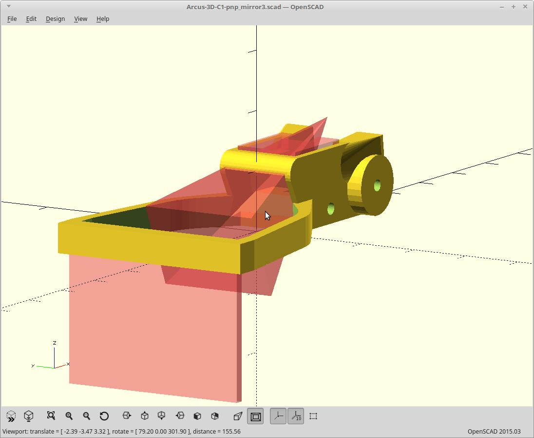
Here is what that looks like, for three 50mm light sections.
![]()
The LED strip will go inside the outer cylinder. I added the sloped inner ring to reduce glare. It shields the main mirror from being directly lit by the LEDs.
The entire light ring is a single wall print except for the attachment point and weighs less than a gram. The LEDs I'm using are pretty strong, so If I left the lights on for too long, it might melt...
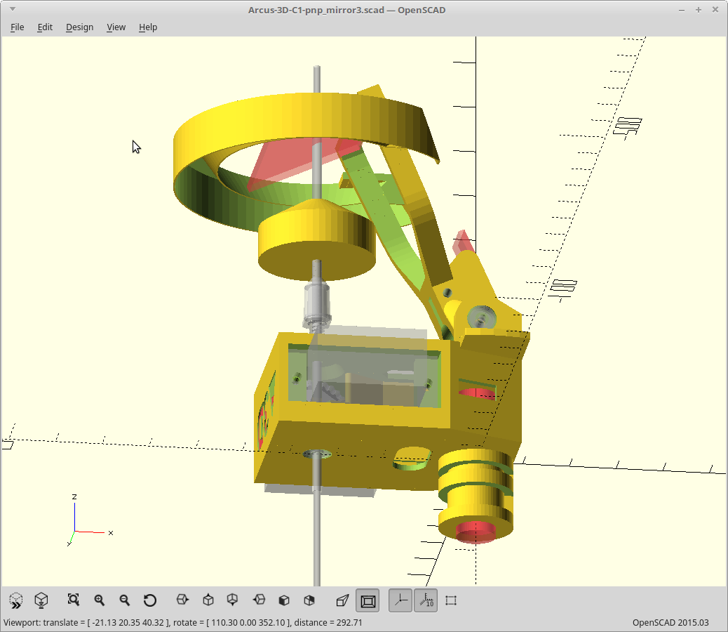
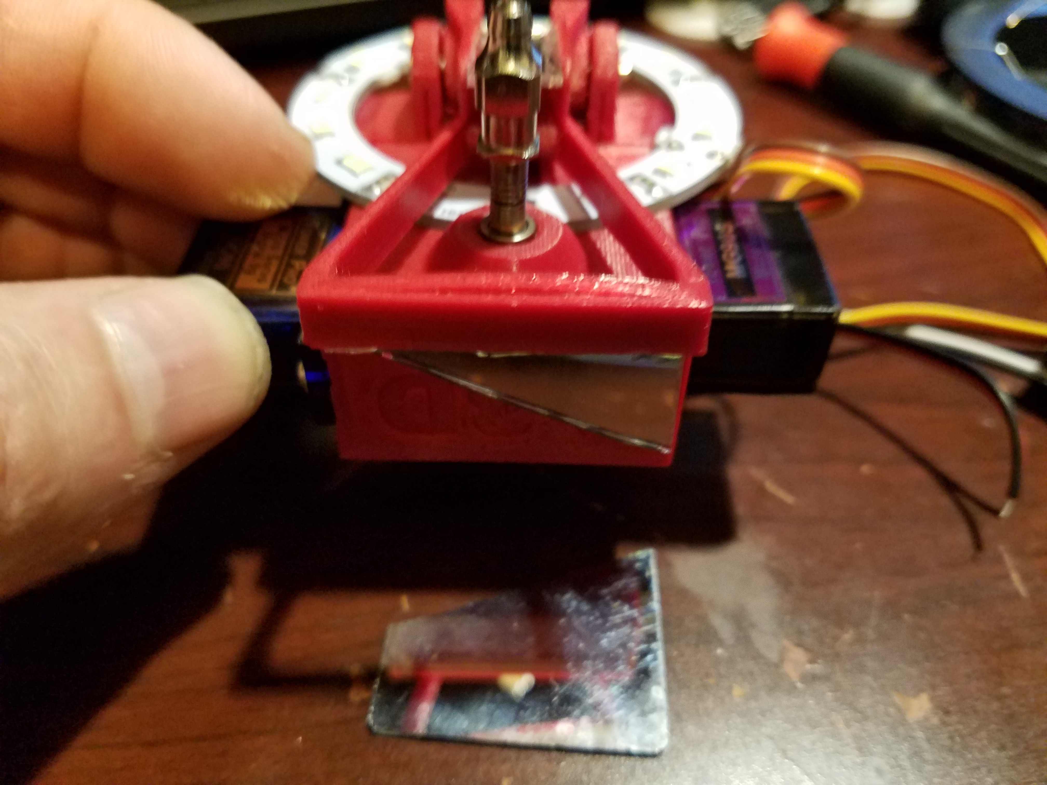
Assembled view.
![]()
I had to move my 'wings' up a little bit as the light ring didn't clear the servo's otherwise.
Reprinting the mirror arm now.
-
Now, with wings.
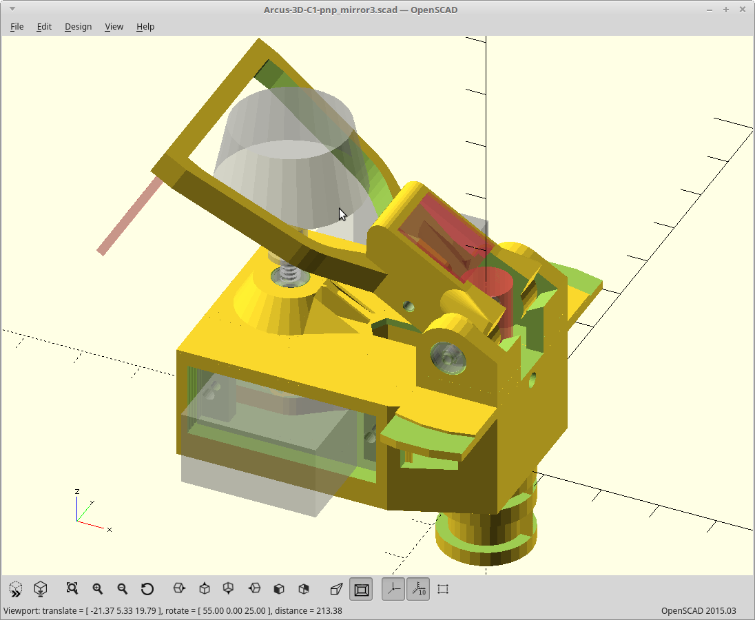
02/20/2018 at 12:12 • 0 commentsWorked on the mirror arm, a lot. Most dimensions are now direct multiples of the nozzle diameter, the camera area is based on rotating a model of the camera, there is a mask beyond the top of the main mirror now, and I added....
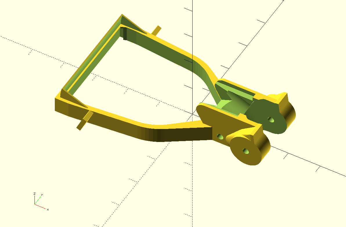
Wings.
![]()
The wings give me a place to snap on a little bracket. The little bracket will let me mount some strip lights at the appropriate height and angle for the bottom vision. It can't be printed as one piece as the lights would need to be below the bed here and I'm not giving up the strength I'm getting from printing this flat.
I'm doing this because it will just be easier and less problematic to have proper lighting instead of trying to get backlighting of the parts working, for now at least.
The hood over the main mirror is a single width extrusion. It printed great, and the weight is now back down to 3.1 grams.
Going to paint it camo black tomorrow and make some new mirrors.
-
How to destroy a mirror.
02/19/2018 at 06:19 • 0 commentsEverything was looking good. My mirrors cut perfectly.
I figured out a better way to cut straight lines in glass. A Post-it note.
Previously I used a straight edge and they were a hot mess. Just the thickness of the post-it was enough for the carbide wheel in the glass cutter to stay on track and sticks just well enough to stay put (a fresh one that is).
All my cuts were within 0.2mm, and all oversized. About 2 minutes of wet sanding on each edge and they looked gorgeous.
Then I got the bright idea to scuff the backing paint to make the paint remover work faster.
Fast forward to the end, my ever so light scuffing of course went through in spots and I have scratches through the silver.
I installed them anyway. Figured I could at least see how my mask was working.
I don't like it. The mask is all around the mirror here, but extends into the viewing area across the bottom.
![]()
I'm going to remove that part of the mask. I think I'll also paint the rest of the mask with camo black paint next time..
The optics were pretty well aligned right out of the box now though. I did nothing to the above other than press the mirrors in and assemble it.
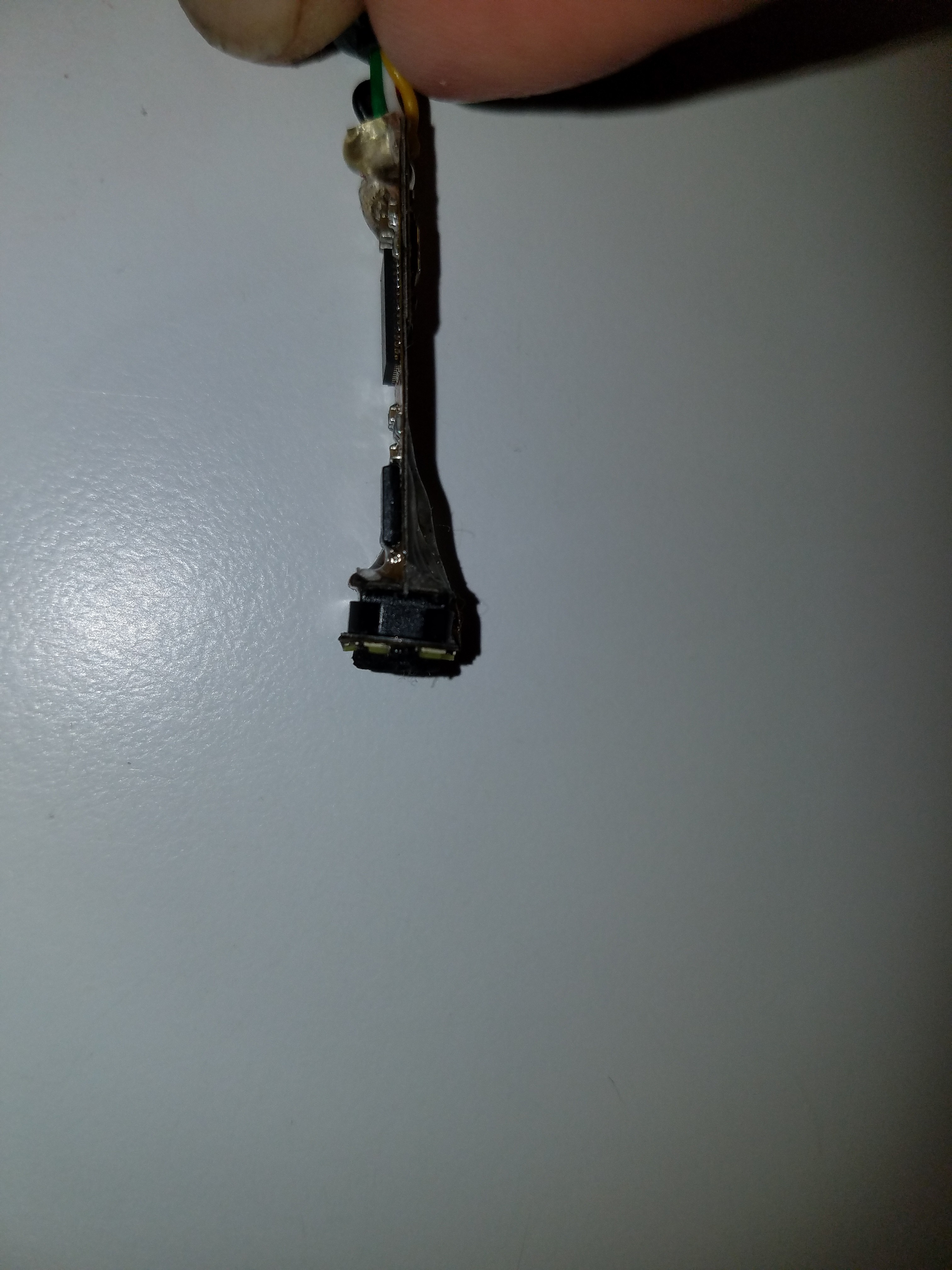
Oh... I scratched the plastic cover on the end of the endoscope... so I removed it. Thought it was glass. Nope. In the meantime, I got a shot of my horribly skewed endoscope camera and gob of UV cure fix.
![]()
That, is where it is optically aligned to the case.
You get what you pay for.
-
Happy accident?
02/18/2018 at 06:37 • 0 commentsDropped the head today, on carpet.
![]()
I think the mirror broke so easily due to my haste in cleaning up the edges. I'll do a better job next time.
I'll be reprinting the arm as removing the mirrors is probably impossible without damage. So I made a couple changes.
I noticed in my camera view the areas past the edges of the mirror could be pretty distracting, so I decided to mask it. This probably won't matter for OpenPnP as it does this in software for vision, but humans will be looking at it too and it may reduce glare from other light sources as well. I already had the beam path as a pyramid, so this was relatively easy.
![]()
I also realized that the only thing limiting it now from rotating larger parts was the width of the arm. Previously the first mirror would interfere first. So I changed the arm geometry to be wider in the middle and I can now clear parts up to 25mm, as long as they are lower profile.
![]()
The bent elbow shape isn't as strong/rigid as the straight path, so I made the arms a little thicker as well which increased the weight to 4 grams.
So does that make this a happy accident? I'll take it..
New arm is printing now.
Need to make new mirrors too.
Edit: Printed.
![]()
The bridge portion of the mask I added had some nozzle width lines spanning to keep the aperture square and they were a PITA to clean up due to the small size. It might be simpler to make this a second part attaching to the mirror.
-
Accuracy.
02/16/2018 at 23:18 • 0 commentsThe mirror arm has to stop at exactly the same angle/place every time for this idea to work.
I've tried to plan for this:
- The mirror arm and servo linkage are designed so the servo arm approaches the apex of it's travel when the mirrors are deployed. This results in the mirror arm extending rapidly, but then slowing down just before seating on the hard stop. It also gives me a huge range on the servo for fine tuning the pressure applied to the stop.
- I have the option of making the linkage spring loaded, or just using a digital servo as well. I'm seeing how well the cheap servos work first.
- A large area, hard stop is included for the extended position.
- I used press fit real bearings with a little preload.
- Stainless pins anchor the arm, also press fit.
- The optics were aligned and then UV cure glued into place.
This seems to have worked. For the video I was swinging the arm itself by hand from one side and driving the servo unpowered in the process to a random angle. If you look carefully at the video, I was still looking right down the bore of my 2mmx50mm shaft straight enough nearly every time to see the circle of light from the other end.
EDIT: I noticed the circle of light wasn't quite a circle. Turns out I still had flashing from cutting the tubing on the end inside the brass bit. Now.. it's a circle... :)
-
Take it to the limit (one more time)
02/15/2018 at 20:49 • 0 commentsThe nozzle needs to give way a bit in the event that the PCB you are placing is warped to prevent breaking components. There are two trains of thought on this. You can either implement the spring in every nozzle, or implement it in the nozzle holder.
I decided to use luer lock syringe needles for my nozzles as they are a precisely machined and commonly available standard. The luer lock itself at least is usually precisely machined. It seems to be hard to find them with the needles actually centered with no runout, but I'll deal with that later. So I implemented the required springy-ness by spring loading the holder and allowing the hypodermic tubing which is the shaft to slide in the bearings.
The spring loading also has the nice side effect of preloading the bearings for reduced runout.
It also gave me a place to put a Z limit switch which can then be used for leveling and to detect nozzles of varying length.
Arcus-3D-P1 - Pick and Place for 3D printers
Open source, mostly 3D printable, lightweight pick and place head for a standard groove mount