 AJ Reynolds
-
11Step 11
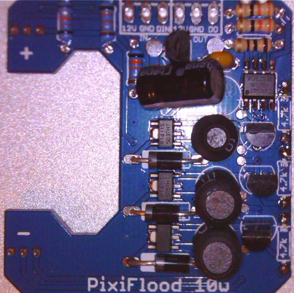
Driver at this point:
![]()
The next steps are Optional Depending on Needs:
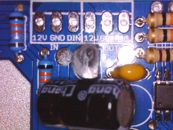
- Optional 1: Verify the clearance between any connectors you may be using and the reflector before soldering to the PCB. Also check clearance of the floodlight body. If an issue exists with clearance, eliminate the connectors and solder wire directly to the PCB. If you are not using one of the "New"/"Slim" housing, a Molex connector WILL NOT fit.:
![]()
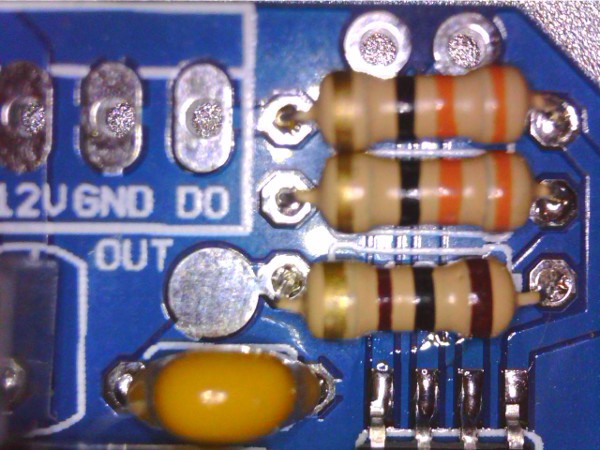
- Optional 2: If there is a need to run the WS2811S at 400mhz instead of 800 mhz, Solder the 2 pin header to the PCB and place the jumper across the pins. If there is no need for 400mhz, the header pin is not needed.
![]()
-
12Step 12
At this Point Stage 4 Assembly is completed: You should follow the remaining test steps outlined in the following video:
For a data source I use an arduino which outputs WS2811 and I can select the color using a simple tact switch. I am able to step through the colors and check measurements BEFORE attaching the LED. If you are interested, let me know I will be happy to share. If you wait until the LED is attached, you will be blinded by the light and have difficulty seeing the board let alone the test points.
-
13Step 13
You now have a fully tested driver board that is ready for the LED to be attached.
I had previously recommended a "tin" process which I have now replaced with the process outlined in the youTube video which can be found here:
The new process should be easier to perform and eliminate issues people were experiencing with too much heat being applied and damaging the PCB traces.
-
14Step 14
FINAL ASSEMBLY:
Be sure to test the LED Driver before installing it in the floodlight body. This is accomplished by supplying 12V power and a WS2811 data stream.
If there are any issues, review each solder joint ensuring that it is not a "Cold" joint and contact is solid. Touch-up of the SMD components may be necessary depending on how they were soldered. Recommend inspection under magnification checking for bridged or incomplete connections.
-
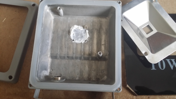
15Step 15
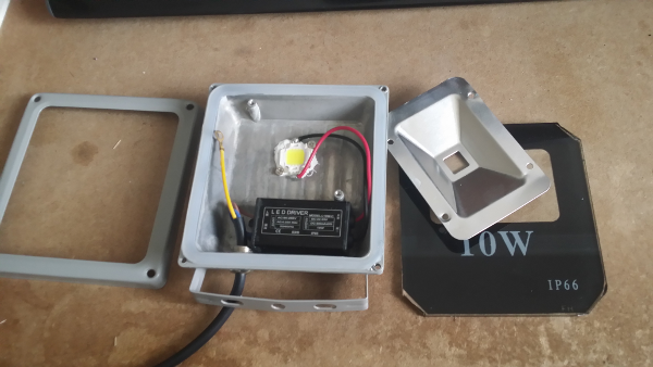
Open floodlight and remove the existing LED and wiring.
![]()
-
16Step 16
![]()
Add thermal paste to the body in the area to be located under the LED.
-
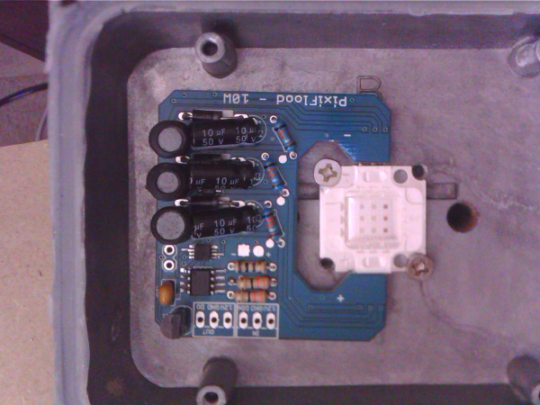
17Step 17
Attach the combined LED and driver module to the floodlight body using the screws removed during the remove step above. (
(The pictured driver is a V1.6 which nobody received. These pictures are only intended to give you an idea of the placement. I will be replacing this with a proper picture in the near future.)
Standard Enclosure
![]()
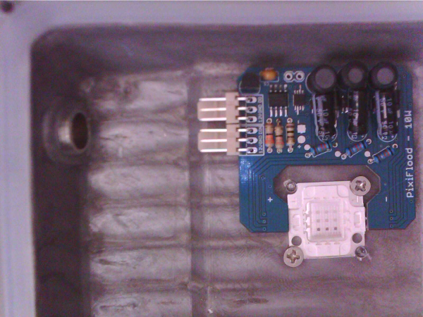
New/Slim Enclosure
![]()
I loop the wires around the reflector post to provide a level of strain relief.
-
18Step 18
Replace the reflector, lens, and retaining ring.
Attach the connector of your choosing and enjoy.......
Discussions
Become a Hackaday.io Member
Create an account to leave a comment. Already have an account? Log In.