 AJ Reynolds
-
1Step 1
THE FOLLOWING PICTURES ARE FROM THE V1.7 VERSION OF THE PCB.
I have begun shipping a new version, V1.9. Assembly is identical, the location a couple of components is slightly different but the instructions are the same. The version number is located on the bottom of the PCB.
The following tools and materials are required to assemble the PixiFlood Driver:
- Soldering Iron
- Solder
- Flush/diagonal cutters
Additional tools that might be helpful, but not required:
- Solder Paste
- Hot Air Station or Reflow Oven
Additional tools and supplies required to install driver into Housing:
- Philips Screwdriver
- Thermal Paste
- Pliers / Wrench to remove wire retainer
Due to the fact this board has SMD/SMT components a good flux is mandatory. I recommend using a re-flow method for SMT components. I used solder paste and hot air (SMD Rework Station).
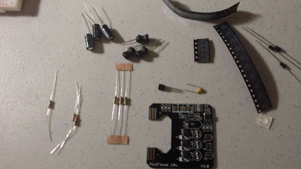
Verify and gather all components associated with the BOM (See Component List)
![]()
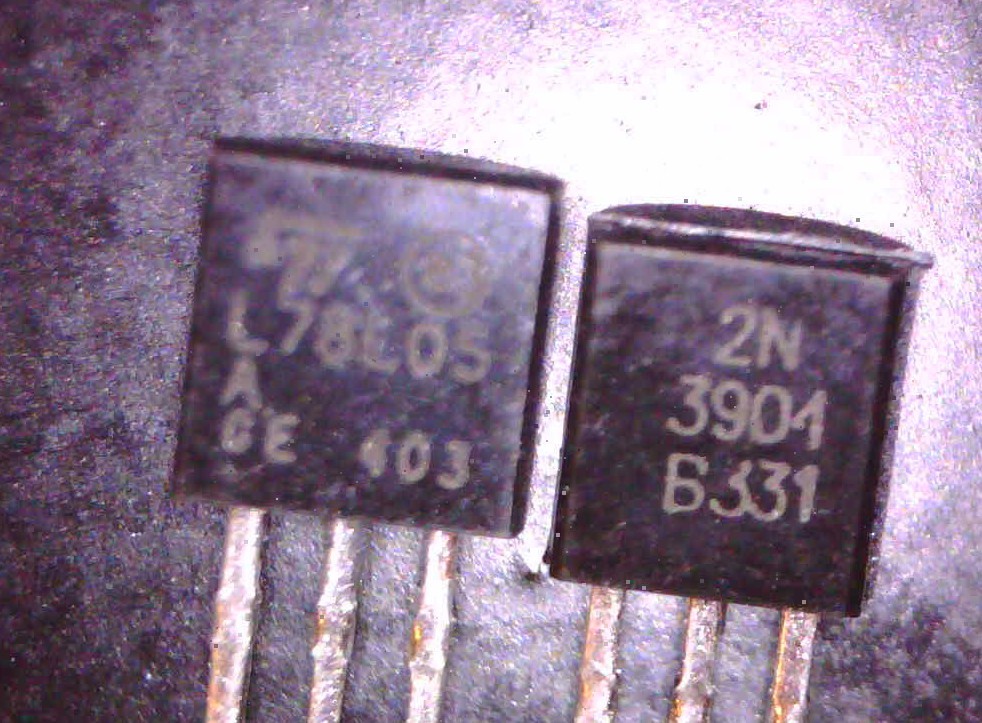
Sorry, you may have to sort the 2N3904 transistors from the L78L05. Both are TO-92 and look identical. Check the the back (Flat) on each, depending on eyesight you may need magnifying glass. The ratio is 3:1 of 2N3904 to L78L05.
![]()
If you order Pre-Soldered, the next three steps have already been completed.
Your first assembly step will begin with (Step 4) the 1N5918 Diodes.
-
2Step 2
STAGE 1 ASSEMBLY:
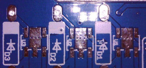
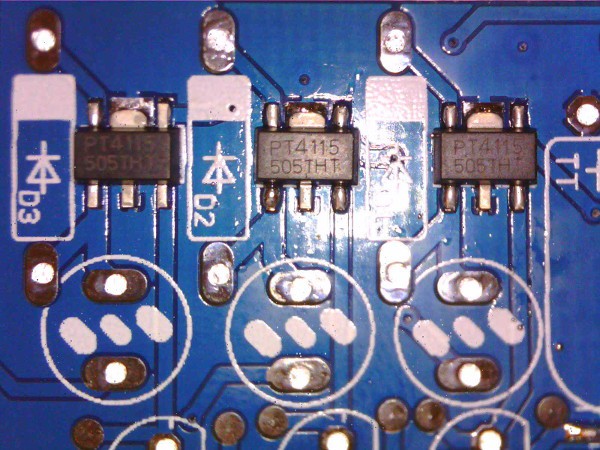
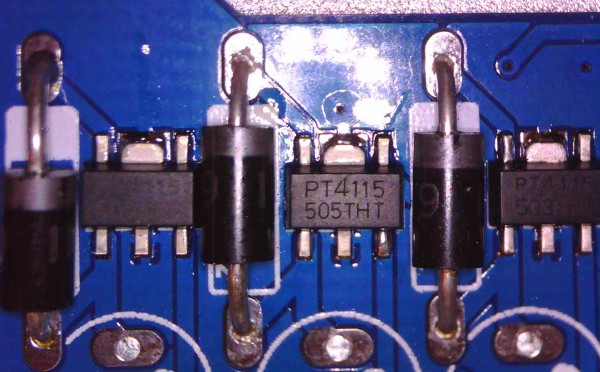
Solder: PT4115BE89 (3) to PCB. Use VERY LITTLE SOLDER ! A fine gauge solder would be helpful and check for bridged solder joints before applying power to the board.
![]()
![]()
There are several tutorials on "Drag" soldering of SMT components available on YouTube. Recommend practicing on something else if you have never attempted SMT soldering before. The PT4115B ICs can be found on eBay and Alibaba for about .20 a piece but may take up to 6 weeks shipping time.
If you encounter issues later, I recommended a simple "touch up" with a soldering iron to ensure proper connection.
-
3Step 3
Solder: WS2811S (IC2) to PCB. Same warnings as the PT4115B.
![]()
![]()
That is the last of the SMT/SMD components, everything from this point forward is Plated Through Hole (PTH).
Stage 1 Assembly is complete. At this point you are ready to conduct the first series of tests outlined in the following video:
-
4Step 4
STAGE 2 ASSEMBLY:
Solder: 1N5819 Diodes (D1, D2, D3) into PCB. They go next to PT4115BE89. Grey stripe on diodes should match orientation on silkscreen. The Grey Stripe should be closest to the LED opening. Trim leads close to bottom of board.
![]()
-
5Step 5
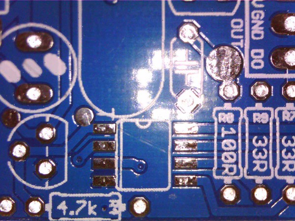
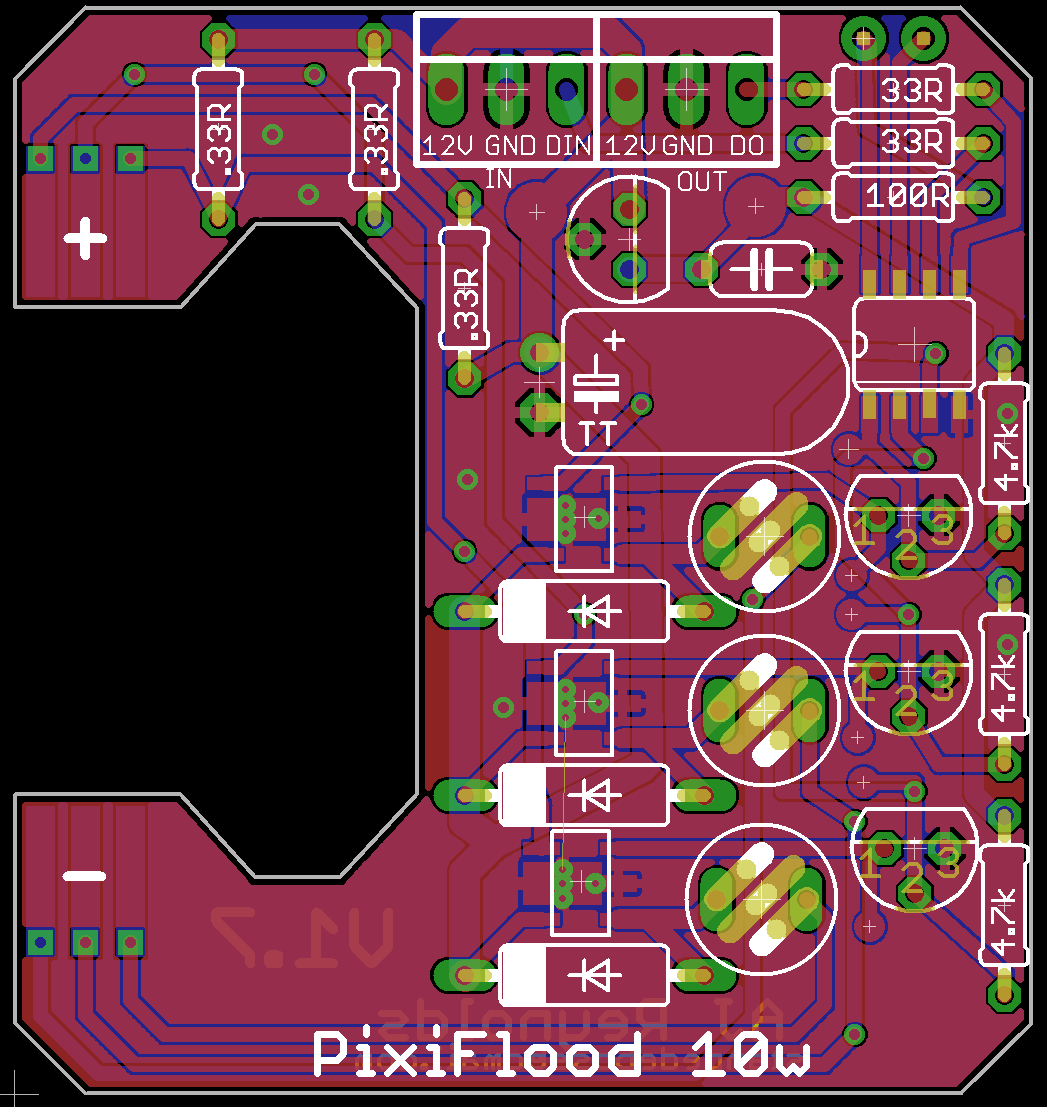
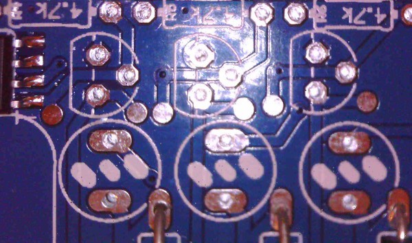
At this point I recommend soldering all the resistors with the exception of the 4.7K to the board. The 4.7K resistors will be the last component added to the assembly in Stage 3. The values and locations are marked on the PCB.
The 0.3ohm resistors (3) control the current levels out of the PT4115BE89 and are sized for 300ma per channel. If your LEDs require more than 300ma, contact me and I can provide you the information on the correct resistor. (350ma requires .27ohm for full intensity).
The spacing is tight on the 33 and 100 ohm resistors, ensure there are no bridges between them.
![]()
![]()
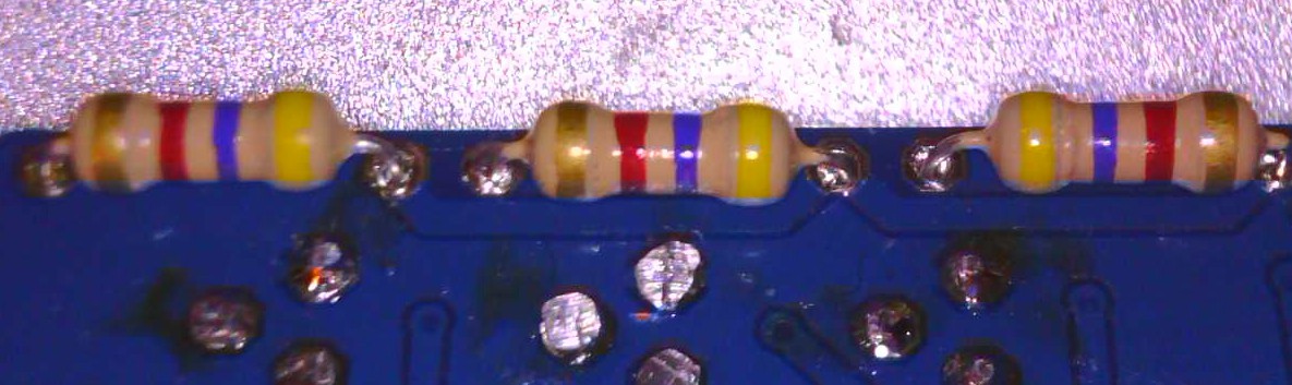
Resistor Values are as follows:
100ohm is on the Left, 33ohm are the Middle and Right
![]()
I sent out 2 different .3 ohm resistors, you would have received one or the other. Please make note that both the .3 and 33ohm have 2 orange stripes. The key is you received 3 .3s and only 2 33 per PixiFlood.
![]()
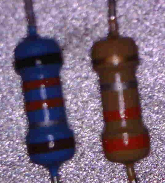
Last but not certainly least, the 4.7K ohm, the early rounds of orders you initially received a 4.7ohm resistor, but I sent out replacements of the correct value. Do not use the 4.7ohm in this project, make sure you are using the 4.7K resistors. They should match the markings below.
![]()
Trim leads close to bottom of board.
-
6Step 6
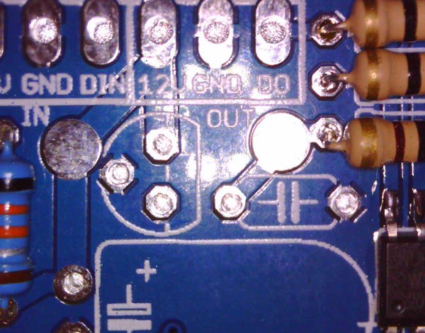
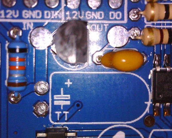
Solder: 1uF capacitor into PCB. the .1uF capacitor is marked 104 and is not polarized. It can be installed without concern to which leg goes where. Please check the marking and let me know if you received a 103 instead of 104. It appears my supplier got some mixed in.
![]()
Solder: L78L05ACZ direction should match silk screen.
![]()
Trim leads close to bottom of board.
NOTE: The test pads in the picture are for 12v on the left and 5v to the right. If possible, connect 12v power and ensure the voltage regulator is working without issue.
-
7Step 7
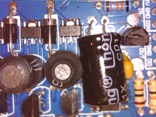
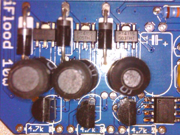
Solder: 100uF Capacitor (1). It will be installed bent over 90 degrees.
Important to note that these are are polarized components and must be installed so the longer lead is inserted into the hole with a "+" sign.
You may wish to delay in actually bending over until testing has been completed since there is a test point for the RED output from the WS2811. It is the small silver circle located just off the pin in the lower right corner of the picture below. It can be difficult to reach with the capacitor bent over.
![]()
Begin by bending the legs to 90 degrees, log leg must pass through the hole with the + and fold back over away from the LED opening. If you received a 50V capacitor, leave the leads a little long so that when folded over it just rests on the top of the WS2811.
(IGNORE INDUCTORS IN THE FOLLOWING PICTURES)
![]()
If you received the 35V capacitor, it is slightly smaller :
![]()
Trim leads close to bottom of board
Stage 2 Assembly is now complete, please conduct the remaining tests outline in the above video.
-
8Step 8
Stage 3 and 4 V1.9 vs V1.7 Assembly differences:
For V1.7 PCBs I recommend not installing the inductors as part of the Stage 3 assembly process, this is due to the lack of access to the test points when they are installed. That is no longer an issue with the V1.9 PCB and concept of Stage 4 can be eliminated and the inductors are installed in this step. For a V1.9 PCB, I would complete the inductor installation based on the following considerations. For V1.7 you will be installing the Transistors at this point.
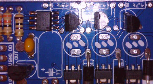
Solder: I prefer to install the 3 2N3904 Transistors at this point. You may choose to install the inductors before if you want to work inside out. The reasoning for 2N3904 before the inductors is that the transistor is shorter and can be difficult to solder if the Inductors are done first:
![]()
![]()
-
9Step 9
Solder remaining resistors 4.7K to PCB, The 4.7K ohm resistors I have begun to solder on the bottom of the PCB. Due to the nature the ceramic coating it isolates the driver from the flood body and provide support to ensure that the though leads do not come in contact with the floodlight, thereby shorting it out. DO NOT use this technique if the light is subjected to extensive vibrations since that will wear the coatings.
![]()
Trim leads close to bottom of board.
For V1.9 complete the remaining Stage 4 steps before or after attaching the resistors, then follow the tests in both of the testing videos.
For V1.7 PCBs this completes the Stage 3 Assembly. Please conduct the tests outlined in the following video:
-
10Step 10
STAGE 4 ASSEMBLY:
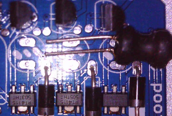
Solder: Inductors (L1, L2, L3) into PCB. Be sure to work the inductor all the way down. This is the highest point and may touch the reflector causing a slight bump which in not an issue:
![]()
![]()
Trim leads close to bottom of board.


Discussions
Become a Hackaday.io Member
Create an account to leave a comment. Already have an account? Log In.