AJ Reynolds
-
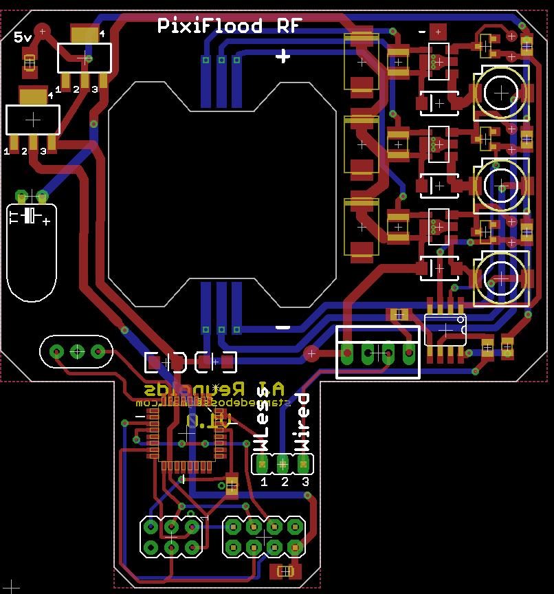
New Board Developed
02/11/2019 at 04:50 • 2 commentsIts been a while since I reported on what was happening with the Pixiflood board. I wanted to expand to powers higher than 10w and had created boards to support 20w and 30w leds that only required 24 volts which was within the component specs.
I've ran into 2 issues, one the pin spacing is different between the various LED Chips and a trend for the LED Chips moving to 30-36 volts which are outside of the 30 volt max of the PT4115, so I set out to solve those two issues and also addressed being able to connect to wifi directly from the board using an esp-01.
The esp-01 uses opensource firmware created for a device called ESPixelStick and works with E1.31 lighting software or directly with MQTT for home automation.
Last year I created a 10w version of the Pixiflood with a built in PixelStick that worked very well. I started with that circuit and swapped out the PT4115 for another constant current driver, I've also eliminated the direct attachment of the LED to the board since this caused issues due to varied spacing requirements. By removing the direct connection and now connecting to the LED via soldered on wires, the new board is able to drive any led chip from 10w to 100w (or Higher) as long as the voltage requirement is under 60v. All current LED chips are 36v or under so my circuit has plenty of headroom.
One of the other advantages of removing the direct connection is the trace length is less than 15% of the previous design which has yielded a significant drop in EMI and noise which has greatly improved the range of the ESP-01 wireless capabilities. Some of the other changes was moving away from a linear voltage regulator to a switching configuration to address connections to higher voltage sources and overheating issues for the 5v circuitry. -
Revised PCB underway
01/05/2016 at 18:44 • 0 commentsAnother year has come and gone, so appears has the Slim 10W floodlight housing I was using. It appears it has been replaced with a smaller version and the PCB as currently designed has issues with using connectors.
I am working on a change that will better fit in the new housing and still enable the use of the wafer connectors that I have been using. I am also moving away from the nRF24 version of the board and exploring using the ESP8266 chip instead. This will offer direct WiFi capability.
-
Revised Video for Attaching LED
09/24/2015 at 18:01 • 0 commentsI have uploaded a revised video on attaching the LED to address the quality issues with the 1st video,
-
Second RF PCB Ordered
08/13/2015 at 21:18 • 0 commentsCleaned up a few issues with the initial prototype and with only minor exception converted the remaining components to SMD. Goal is to minimize any chance of shorting the driver against the Floodlight case.
![]()
I added the capability to jumper the Data Signal to be sourced from the nRFL24 or the input wires. This will allow testing without having to deal with the wireless.
-
Stage 4: Testing and Troubleshooting (Revised)
08/11/2015 at 14:59 • 0 commentsThere was an issue with the volume in the third video. I had to rework the content since I couldn't fix the volume on the previous video.
The new video can be found at::
-
Final Testing and Troubleshooting Video
08/09/2015 at 09:56 • 0 commentsThe last video on the PixiFlood Testing and Troubleshoot process is available on youTube:
-
New Video Uploaded to youTube
08/09/2015 at 01:31 • 0 commentsJust uploaded the second Testing and Troubleshooting video to youTube. It can be found at: https://www.youtube.com/watch?v=gL9qjLBShj0
-
Gerbers and Eagle Files are Available on Github
08/06/2015 at 05:36 • 0 commentsAs I have been planning on doing for some time, I have made the files available on GITHUB. There are 3 versions of the board, the 1.7 version is the board I have been working with for the last few months and is the only one in circulation.
The 1.9 version is an improved version which I will be using going forward. Changes are covered in a youTube video you can find in the project logs.
The 1.10 version is a work in progress and has not had the initial prototype completed. There are additional changes planned.
The RF version of the board I am still working on, it is near completion and is working but before I make it available I want to make sure.
-
Board layout modified
07/27/2015 at 15:10 • 0 commentsBased on feedback from the users I have modified the board to make it easier to build and test. Changes are covered in the following video:
-
Testing and Trouble Shooting Videos
07/27/2015 at 15:07 • 0 commentsI have create a series of youtube videos that walks you through the process of testing and trouble shooting issues with the LED Driver.
It also should provide insight into the design since it walks through every connection and specifieds the expected voltages and behavior
Part 1 can be found at: .