Mike Thielvoldt
-
Moving Ignition timing to the ECU
07/20/2019 at 00:19 • 0 commentsMy hall effect signal has been slowly deterioriating. I am using this as an opportunity to bring the ignition timing under control of the ECU. In doing this I will be replacing the 1984 distributor, which featured centrifugal and vacuum advance with a 1986 distributor which has neither advance mechanism because these features were moved to the ECU for that model originally.
Basically, I'm following in VW's 1980's footsteps. Below is a fun video of me testing that the programmed timing is going to fire when the rotor will be pointing at a plug wire.
-
Parameter Access from Dash Terminal
03/16/2016 at 21:05 • 0 commentsThe Problem: poor parameter access
I was having this experience where something would be not quite right, but I couldn't do anything about it until I broke out the laptop and plugged into the USB. Most of the time it would be a simple matter like a parameter was a little high or low, but sometimes even the laptop didn't give me enough access to fix those problems.
An example: When the engine is cold, the mixture is fuel-rich to compensate for the lower available thermal energy for ignition. In the carburetor days, the engine would be said to be "on the choke". Of course, as the engine warms up, the extra enrichment can taper off. The exact shape of this enrichment curve is experimentally determined, since it would be impractical to model all of the contributing factors, but easy to just try numbers and listen.
And yet, I found it difficult to hook up the laptop and tune by ear. Not only is the laptop clunky and not always present, but I also couldn't send inputs very quickly, because I had to copy and paste a whole new pair of arrays into the terminal window. As the engine warmed up, I would lose my chance to tune.
The Answer: a button-navigable menu of all parameters
Having only 20 buttons and about as many parameters, I decided to use two buttons to scroll (up or down) through the list of parameters. The selected parameter can then be increased or decreased by two more buttons, and a final pair of buttons amplifies or diminishes the effect of each increase or decrease button-press. In other words those final two buttons let you determine the coarseness of your adjustments. A final button is used to select which point on the curve you're editing in the case that the "parameter" you are editing is actually a curve.
So if you're tuning the cold-engine enrichment curve, you would tell the ECU to auto-report the coolant temperature on the screen, then navigate to the enrichment-curve and select the point nearest the current coolant temperature. Now, nudge the enrichment number up or down until you like how it sounds, and move on to the next point on the curve as the engine warms up.
All I can say is: I love easy access!~
-
Adventures and Dash Terminal v1
01/22/2016 at 10:02 • 0 commentsIt has been almost forever since my last log, and to my followers, I apologize.
In point of fact, I'm terrible at logging things, but I did manage to write down some of the process as I went through it, so here I will bundle not one, but Three logs that I wrote long ago, but didn't post until now:
From some time in May 2015:
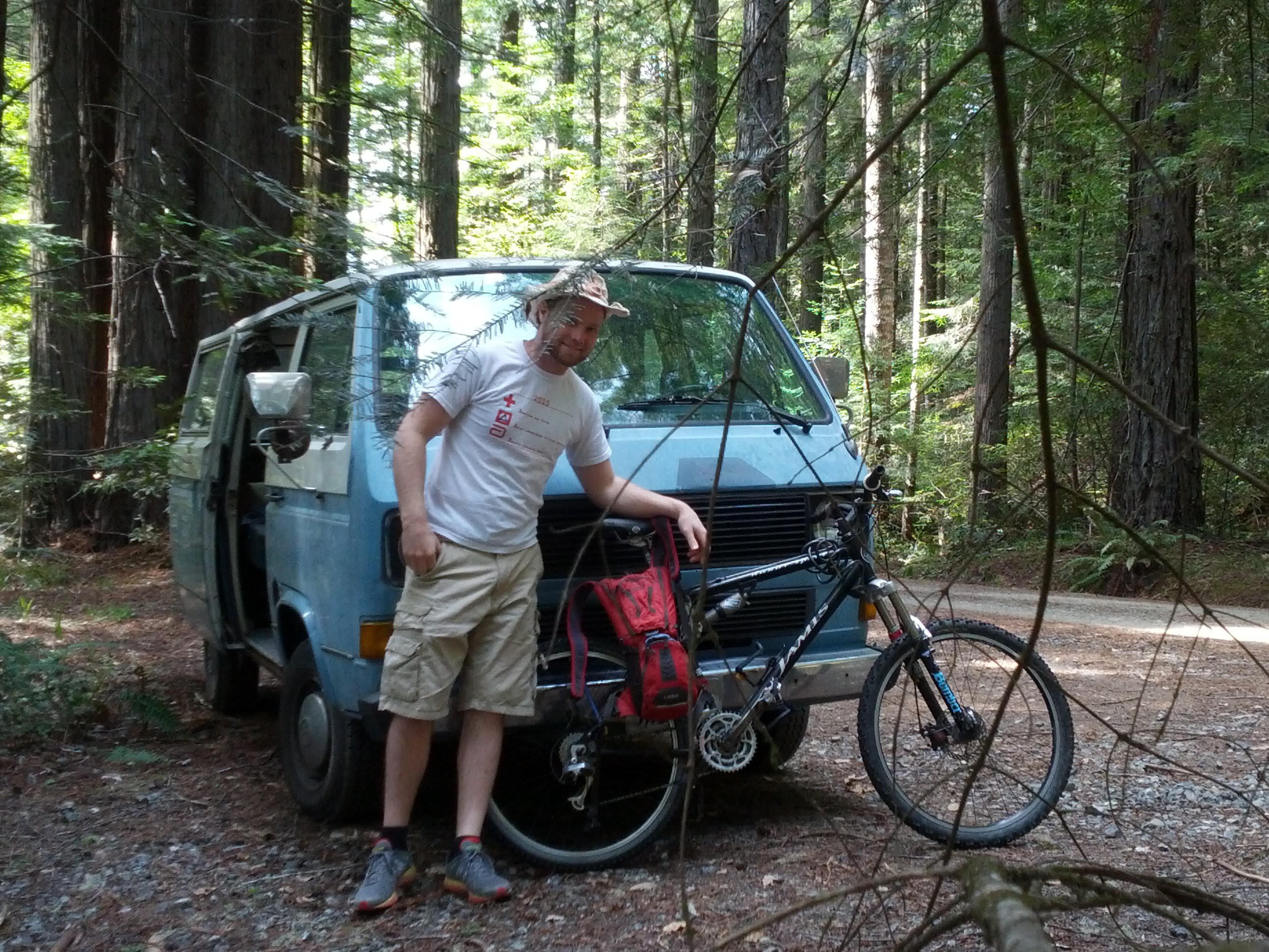
Greetings from the Road
![]()
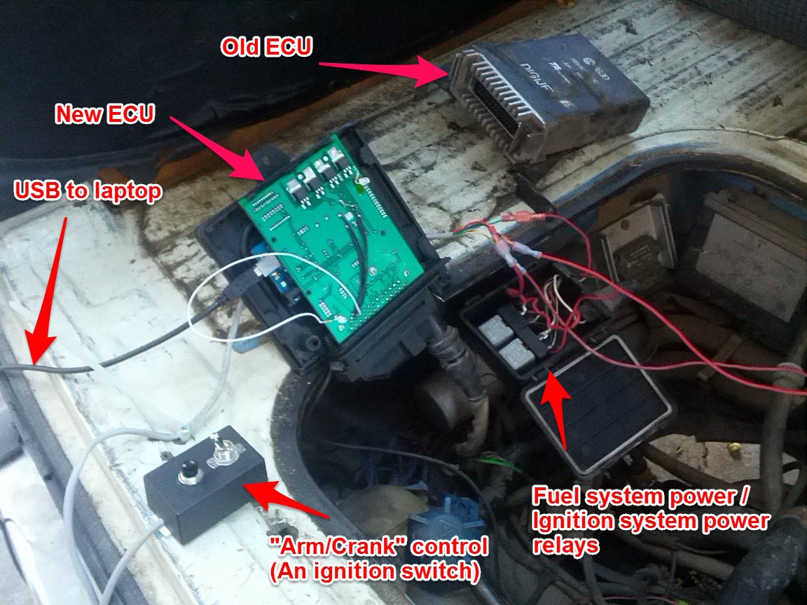
The road trip has begun. I write this from the woods outside Mendocino, CA. New to the ECUality arsenal is the dash terminal - an Arduino Mega 2560 equipped with an Xbee and lit LCD display. The unit is powered from an ignition-switched 12V line from the dash fuse panel, so it comes on when the ignition is turned on. The ECU, which is in the engine compartment, communicates with the dash monitor via the Xbee wireless board. All serial functionality can be easily directed to USB or Xbee, so the dash terminal can access the full compliment of commands.
Currently I am only using the dash monitor it to measure oil pressure, but much more is in store for this unit. Eventually it will enable all of the following:
Remote control access to common commands (performance mode, log data)
Remote control selection of readings to display.
Alerts for electrical faults and unsafe sensor readings
Control the bow-mounted pneumatic traffic axe. (just kidding. probably)
And maybe: Remote re-programming (still mulling this over)
From a couple days later
Houston, We have a miss
So far, ECUality has gotten us to our destinations on the road trip, but the steep, winding driving through the coastal redwoods has surfaced a miss of unknown origin, and it appears to be getting worse. A list of observable miss properties:
- Duration: each miss lasts an estimated 1-10 cylinder fires (it bucks)
- Frequency: Started once every few minutes, now I get several misses in succession when exiting every curve.
- Throttle dependency: no definite dependency
- Warm/Cold dependency: seems to happen mainly when engine is warm, but not 100% sure it doesn't happen cold
- RPM dependency: More pronounced at low RPM, but no strong dependency.
Guesses about cause :
- Closed-loop calibration is sending mixture too lean.
- Tach signal from Hall sensor is cutting out
- Air sensor signal is cutting out
- injector driver is cutting out
Techniques to determine cause:
- Add ECU code to check for and report anomalous readings for RPM and air flow
- Manually enrich the mixture and see if performance improves.
- Add ECU code to talk to the injector driver via SPI. (Wire library)
I'm going to do all of these. In this order.
From some time in June 2015
Miss Resolved
ECUality development has slowed, but it has by no means stopped. I have now taken ECUality up the California coast twice to Mendocino and once up to the woodlands near Eureka.
It hasn't been smooth sailing every time. The trips to Mendocino revealed a miss, which I later diagnosed as being caused by a mistake in the tach input circuit. I had erroneously assumed that the tach signal was the same 0-5V coming from the ignition module as it was going in. It turns out that while the signal going to the ignition module was 0-5, the signal from the module (and to the ECU) was 0-12V. My circuit had protection that kept it from being damaged, but the signal was clipped so severely that the signal to noise ratio was way bad, and occasionally the ECU would sense noise as extra tach pulses.
The code I wrote to check for anomalous RPM readings (see previous post) was what lighted the way. Every time the engine would miss, I would see RPM fault reports on the dash terminal. This let me know to look at the tach sub-circuit for problems.
The solution was very simple. I hacked a voltage divider onto the board at the input to the comparator to bring the signal down to the 0-5V level that the Schmitt trigger wants.
-
Low Emissions? - getting there.
04/24/2015 at 22:13 • 0 commentsLast week was all about measuring emissions. Standards for acceptable emissions levels are set by the state of California, so I decided to see if I could meet the same standard, using the CA-certified test centers. This program is called, "SMOG CHECK".
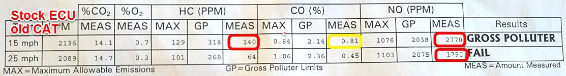
Smog Check results before and after:
![]()
![]()
![]()
- Still room to improve in the low-speed category,
- Looking quite good in the 25mph (higher-load) category.
- The last test incorporates a catalytic-converter change, so comparing the first two says more about the ECU.
- This vehicle does not have EGR, (exhaust-gas recirculation) which means that it depends heavily on the catalytic converter to reduce NOx. You can clearly see how the ECU had little if any effect on NOx, but a big effect on HC and CO. Meanwhile, the new CAT obliterated the NOx
To get through a smog test (this applies to the STAR test - a stringent test required of older vehicles), a technician (as in: not me) drives the vehicle onto the chassis dynamometer, hooks up a timing analyzer and a tailpipe gas collector, does a visual inspection, then uses the engine to spin up the dynamometer to the required speeds for a test and maintains that speed while the gas analyzer checks the exhaust composition. All the checks and setup require a stable idle, good starting, and a quick transition from idling to under-load auto-tuning to pass the test. Needless to say, this took some work to achieve.
RPM Idle Stabilization
The biggest code-hurdle was stabilizing the idle. Because I decided to use all the original sensors, I was restricted to using a single-wire Oxygen sensor. This does not have a heater built in, so when the exhaust flow stops putting enough heat into the sensor to keep it operating, the signal becomes meaningless. This means I could not rely on my O2 sensor to control the idle fuel settings. I learned this the hard way at the first test-center: I had very rough idle, and ultimately couldn't finish the test. Further, the number of re-starts drained the battery so Kim and I had an embarrassing push-start out the lot. Nice try, no dice. I needed another signal to base idle-adjustments on, and there is really only one other choice: RPM.
The theory is: when we're idling, the engine is out of gear so adjustments to the fuel mixture affect the idle speed. Speaking approximately, we want to be on the lean side of the amount of fuel that gives maximum RPM to prevent carbon buildup, high CO and wasted fuel. The old carburetor-tuning methodology (thanks Dad) goes like this:
Turn the appropriate screw to lean the mixture until the RPM noticeably drops, then turn it back a set (usually small) amount and there you go. I adopted the same methodology.
- Do this adjustment only once every X seconds
- Measure the RPM using a moving average to filter noise.
- Start leaning the mixture (decreasing fuel) little by little.
- When the averaged RPM drops by X, stop decreasing.
- Add X offset back to the fuel input.
- Apportion the net change to the Local and Global buckets.
- Re-start the timer
Of course, the local-global distribution of change has it's own rules, but I'll cover those in a coming update.
SMOG speculation and What's Next:
The idle work really showed the advantage of having a heated O2 sensor, both for emissions and for simplifying control heuristics. Further, I suspect the O2 sensor is why I nearly failed for having high CO at 15mph on the last test, when I was so good in that category on the previous test. Between the two tests, I also tried to add a pull-down resistor to the O2 sensor output, and that damaged the new O2 sensor, making me take the last test with an older one. O2 sensor aging is documented as creating a rich-shift. I already have the hardware to go to the latest LS4.9 wide-band O2, which I expect will give far more consistent useful information.
I do believe the best context for making the next improvements will be on... A... Road Trip. To hell with controlled environments!
Stay tuned.
-
Tweaking like a Boss
04/14/2015 at 08:11 • 2 commentsPeople, we are now
Automatically tweaking fuel levels while driving!
I have added logic for determining the appropriate times to engage 3 different modes of injector pulse adjustment, and appear to be correctly applying those adjustments.Local v Global changes: A global tweak affects the rate of fuel injection at all RPM's and all loads (air-flows). A local tweak affects the fuel injection rate at a specific RPM and load.Map: When I refer to a "Map", I am referring to the 2-d table representing injector pulse duration vs engine load (x) and RPM (y).Tweaker modes- Global-only adjustments based on maximizing RPM
- global-only adjustments based on O2 sensor
- local and global adjustments based on O2 sensor
Mode 1 takes over when the engine is cold and idling.
Mode 2 takes over when the engine is warm, but has not been warm for long.
Mode 3 takes over when the engine has been warm for a while and the engine has been pulling (as opposed to coasting - a state that turns the injectors off) for a minimum amount of time.
Noticeable power improvement
The seat-feel is much improved over the original ECU. I did not expect this to be the case yet, but the impetus for the project was, in large, a difficult-to-correct hesitation when accelerating using the original ECU. This has already been eliminated. Woot.
Next up:
- fix bug with RPM measurement when engine is off.
- get a manual SMOG test to measure emissions.
- Start using Wide-band O2 hardware
- Build wireless dash-monitor.
-
Function Pointers, meet Serial protocol.
04/10/2015 at 01:41 • 0 commentsI was already doing this with function pointers:
task[0] = readAirFlow;			ms_freq_of_task[0] = 50;
task[1] = readO2Sensor;			ms_freq_of_task[1] = 50;
But now I'm also doing this:
ESerial.addCommand(F("Winj"), Map::write, &inj_map);
ESerial.addCommand(F("rinj"), Map::read, &inj_map);
ESerial.addCommand(F("Sinj"), Map::save, &inj_map);
ESerial.addCommand(F("linj"), Map::load, &inj_map);
It adds a serial command that gets executed on a specific object (in the above example the object is "inj_map" ).
So after calling the above, when I type: rinj into the serial monitor window, the Arduino runs the "Map::read" function on the "inj_map" object. In this case, that prints the injector map out on the serial port, so you can see what's there.
So far I have almost 50 commands, which is why I needed to get it down to a 1-liner.
-
Classes, Classes
04/08/2015 at 22:43 • 0 commentsIt's official. This is already the biggest program I have written to-date. And with that realization came a vision of the future: one in which the program got so clunky and large that it stopped being fun to work on.
So on the heels of my first major project success, and on the edge of diving into optimization, I am cooling off, looking back and doing some extensive housekeeping. (more like re-modeling)
Where it hurts:
- When adding new scaling arrays, it takes a while to add all the update, report, load and save functions.
- When I'm communicating with the arduino, updating new parameters is getting clunky and depending on copy-paste.
- when I have to add new serial controls, that switch is getting huge, and I can't remember which character means what.
- range-checking things is getting really tedious.
Troubling prognoses:
- many new commands for error checking and tuning will tax my mind even more.
- adding items to data logger will create similar pains as I'm facing with serial now.
- new functions for talking to peripherals will make things bigger.
- the optimizer will not be a good roommate; it needs its own space.
Treatment plan:
- encapsulate major types of data-structures into classes to help manage new parameters, maps, etc.
- created function templates for doing basic things on various simple data types.
- create wrapper classes to manage lists of objects and actions (think: list of serial commands, list of eeprom-backed parameters, list of logged variables)
Do you have a suggestion on program design that feels relevant to the above? Please share!
-
First Fire
04/02/2015 at 16:04 • 0 commentsFirst (successful) Vanagon test
![]()
Last night, we had our first light-off and the result was very, very promising.
- Stable idle,
- Reliable starting (once I got the right setting),
- All sensor reading made sense,
- Great throttle response!
A few of the steps that got me here:
- Beefed up the rear Arm/Crank control circuit (because starter solenoids take serious amperage!)
- Verify actual injector pulses with LED on injector driver output.
- Ask the original ECU for cranking pulse duration (turns out this is totally independent of Air flow or temp.)
- Add automatic printout of injector pulse duration while cranking (helps tuning to start)
- Tweak cranking duration so choke-adjusted result matches original ECU's
- Fire it up.
- Play with global offset to maximize RPM (at first, until O2 sensor heats enough to come online)
- Continue tweaking, but now using O2 signal
- Try opening the throttle - Great result: no hesitation, RPM comes right up.
At that point my CO meter started going off, so I called it a night. Going to need to handle the exhaust gas.
What's next:
- Duct Exhaust away
- Add Temperature warning (in case it gets hot)
- Optimization routine
- Define the optimization modes. I'm thinking: warming up, warm-global, warm-local
- Define criteria for entering each mode (O2 sensor online, timer, temp, load)
- Enable the data structures for keeping track of optimization history
- Add some optimization system auto-reporting
- Add optimization modes one at a time, testing each
- Field tests.
- Take it to SMOG shop to see how we're doing.
-
Characterizing the VW ECU
03/11/2015 at 13:43 • 1 commentGoals:
- Obtain a fuel map from the original VW ECU as a starting-point for ECUality
- Answer questions about how the original ECU behaved, such as:
- What aspect of the O2 sensor signal does it care about? (threshold crosses/sec? DC voltage?)
- Generally, does the optimization routine change the "shape" of the map, or just apply a global offset?
- How fast does the optimization respond?
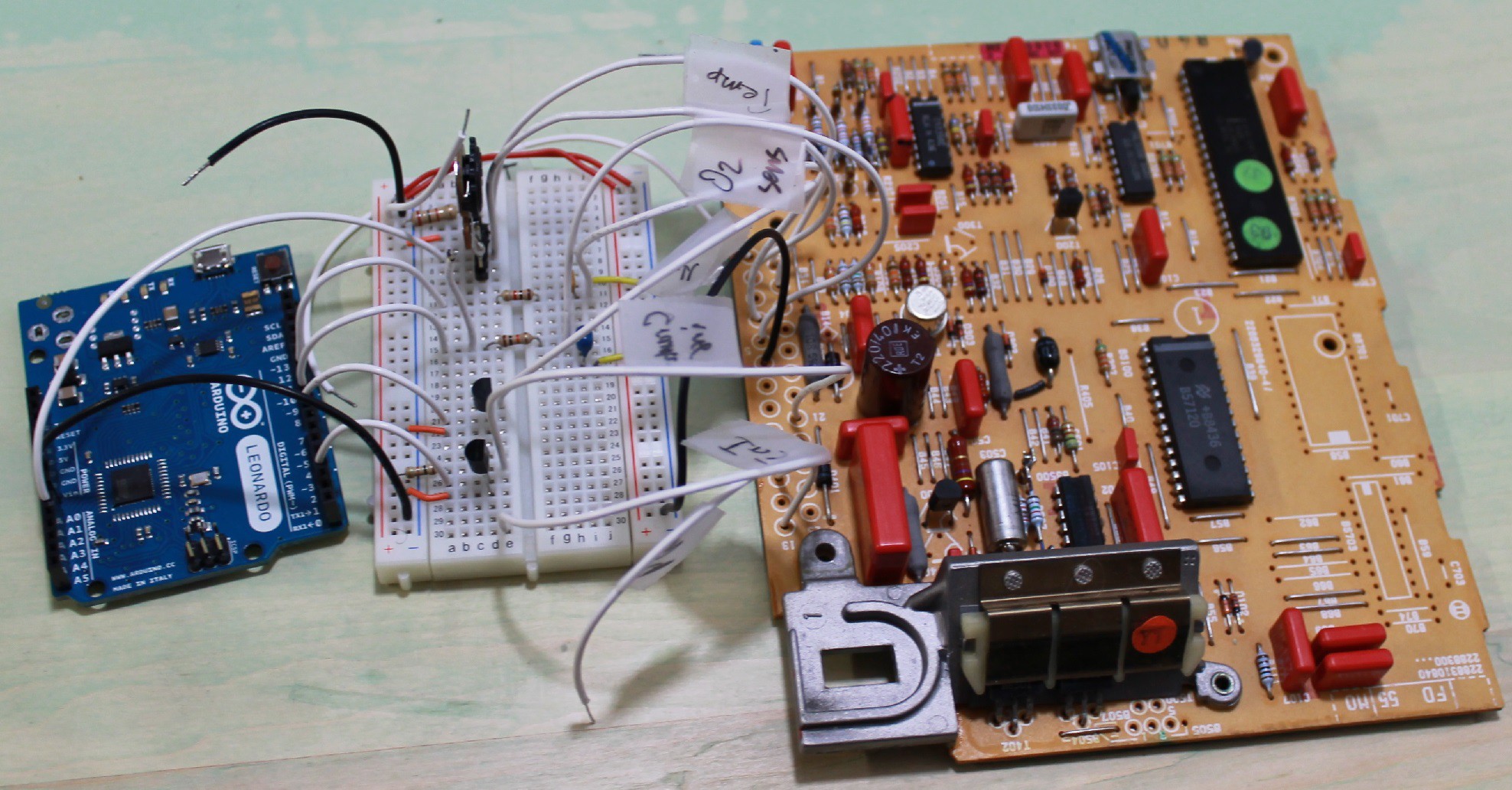
Here, I use an Arduino Leonardo to send signals to the original ECU that simulate sensor data from a running engine. With that stimulus going in, I record the pulse-duration of the injector signal coming out.
The breadboard between the Leonardo and the ECU contains:
- a couple RC (low-pass) filters for smoothing PWMs into analog voltages.
- a couple N-mosfets for handling a voltage-shift (0-5V to 0-12V)
![]()
ECUality1
A light, open-source Engine Control Unit (ECU) using Arduino