-
1Proximity-based Switch
In order to turn the remote control system on, an external switch was used. You can think of it as a button, except you don't need to press it, just hover something above it. It also works apart from the circuit triggered, which means it works as a wireless trigger. To do so, an infrared-based, proximity switch was combined to radio-frequency modules (encoders, decoders and antennas). You can think about this switch as a low-cost button that you can "press" while you're at the kitchen to turn something on at the living room. The details on construction and implementation are given below.
Transmitter side of the switch
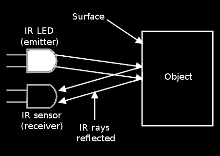
The proximity switch is based on the principle of a simple line follower circuit. An infrared LED (IR LED) is placed beside an infrared sensor (IR sensor), as depicted on the image below, with both pointing to the same direction (up). This circuit is kept close to the user to be used as his/her "hover button". Once an object is placed over the IR components, the infrared light emitted by the LED is expected to be reflected by the object onto the IR sensor, which will "detect" the approximation of the object through the change on the voltage of its anode.
![https://s25.postimg.cc/vu1qsf39r/2_-_39_Zqh1v.png]()
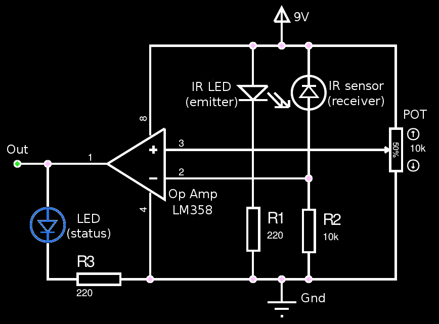
Since that voltage change is really small, an operational amplifier is used to (guess what) amplify this signal. The Op Amp (IC LM358) is also combined to a 10 k Ohm potentiometer to be used as a voltage comparator: when the voltage on the IR sensor's anode is greater than the voltage on the potentiometer, the 5V from the battery goes to a red LED, which provides a visual feedback for the user about the approximation of the object. Plus, a resistor was placed in series with the status LED in order to divide the voltage that goes to the pin of the radio-frequency encoder module (HT12E), as can be seen on the image below.
![https://s25.postimg.cc/4jgfkifsf/3_-_i_Zwl_YDg.png]()
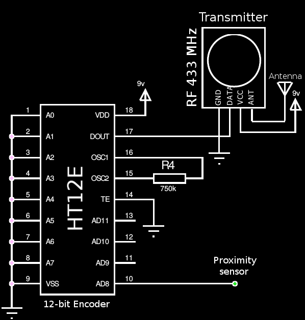
The HT12E integrated circuit is used to transmit an encoded 12-bit parallel data via RF transmitter module at 433 MHz frequency. The same voltage used to turn the red status LED on is put on the encoder's pin number 10 (AD8, input data pin. There's also other 3 AD pins, since the IC has 4 channels). The data pin of the RF-module (transmitter antenna, Tx), on the other hand, is connected to pin 17 of HT12E (DOUT, data output pin). The DOUT pin serializes the data to the antenna if, and only if there's a high voltage on the AD8 input pin. Otherwise, no RF wireless signal is generate by the transmitter circuit.
![https://s25.postimg.cc/rxoewfpzz/4_-_vjf8_Rm_X.png]()
Receiver side of the switch
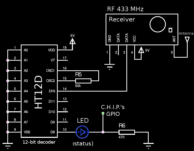
The receiver part of the wireless switch stays close to the microcomputer in order to (guess again) receive the encoded signal from the RF-Tx modules, decode the information and turn the remote control system on. The RF-module (receiver antenna, Rx) output pin is connected to decoder's pin 14 (DIN, input pin). The HT12D integrated circuit reads the serial data captured by the RF-Rx module on its pin 14, and decodes the 12 bits trying to find a match the address. If the data is successfully decoded, the output is generated in one of its data pins. Pin 10 (D8) was used here. The schematic is shown below.
![https://s25.postimg.cc/58z7wvo1r/1_-_AHbd_SOd.png]()
The HT12D's D8 output pin is connected to an input pin (GPI) of the microcomputer. Since the C.H.I.P. supports 3.3V of input voltage, a voltage divider circuit was formulated with an LED and a resistor to limit the voltage at the output of the decoder, which avoids burning the microcomputer pin.
You can see a demonstration of the wireless, proximity AT switch on the video below:
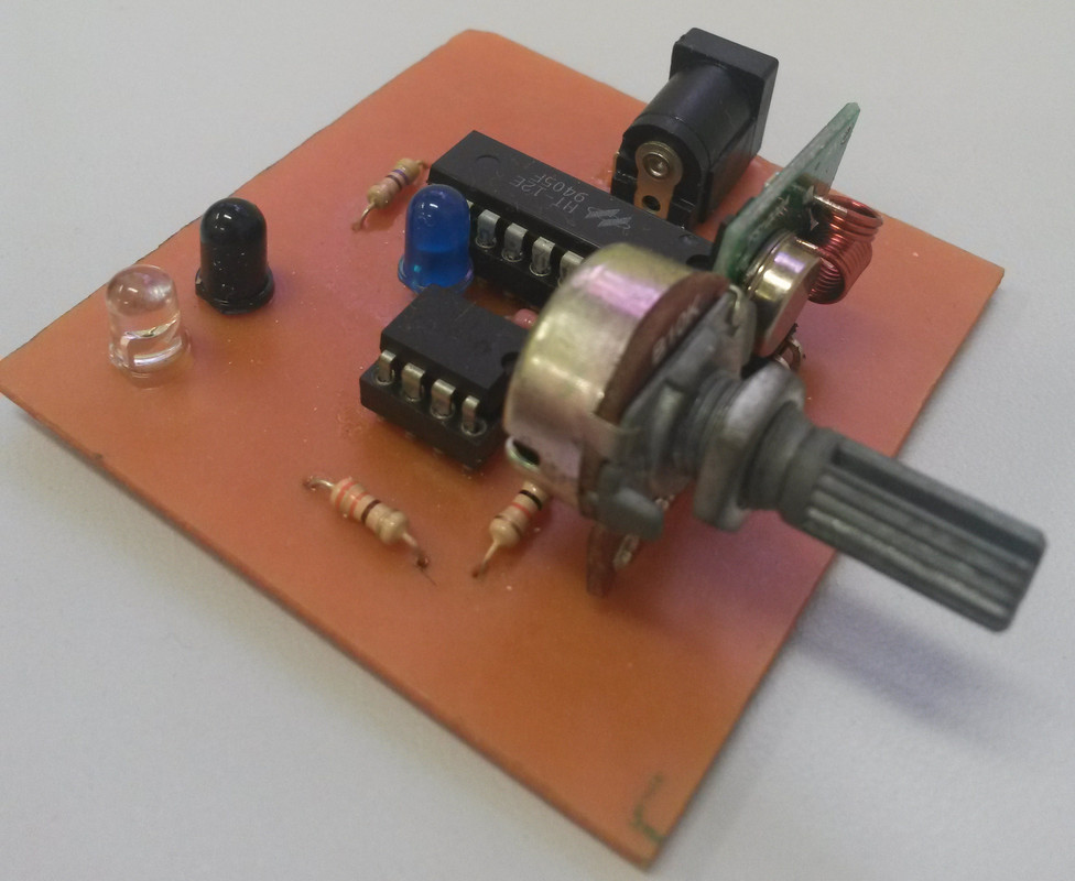
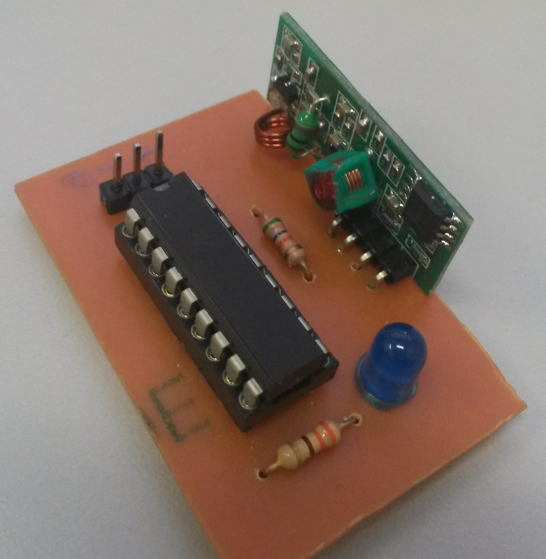
Designing and Building PCB
The board was designed on Kicad. You can find all files at Github.
and also on files section.
Trasmitter module
![]()
Receiver module
![]()
-
2Puff-Based Switch
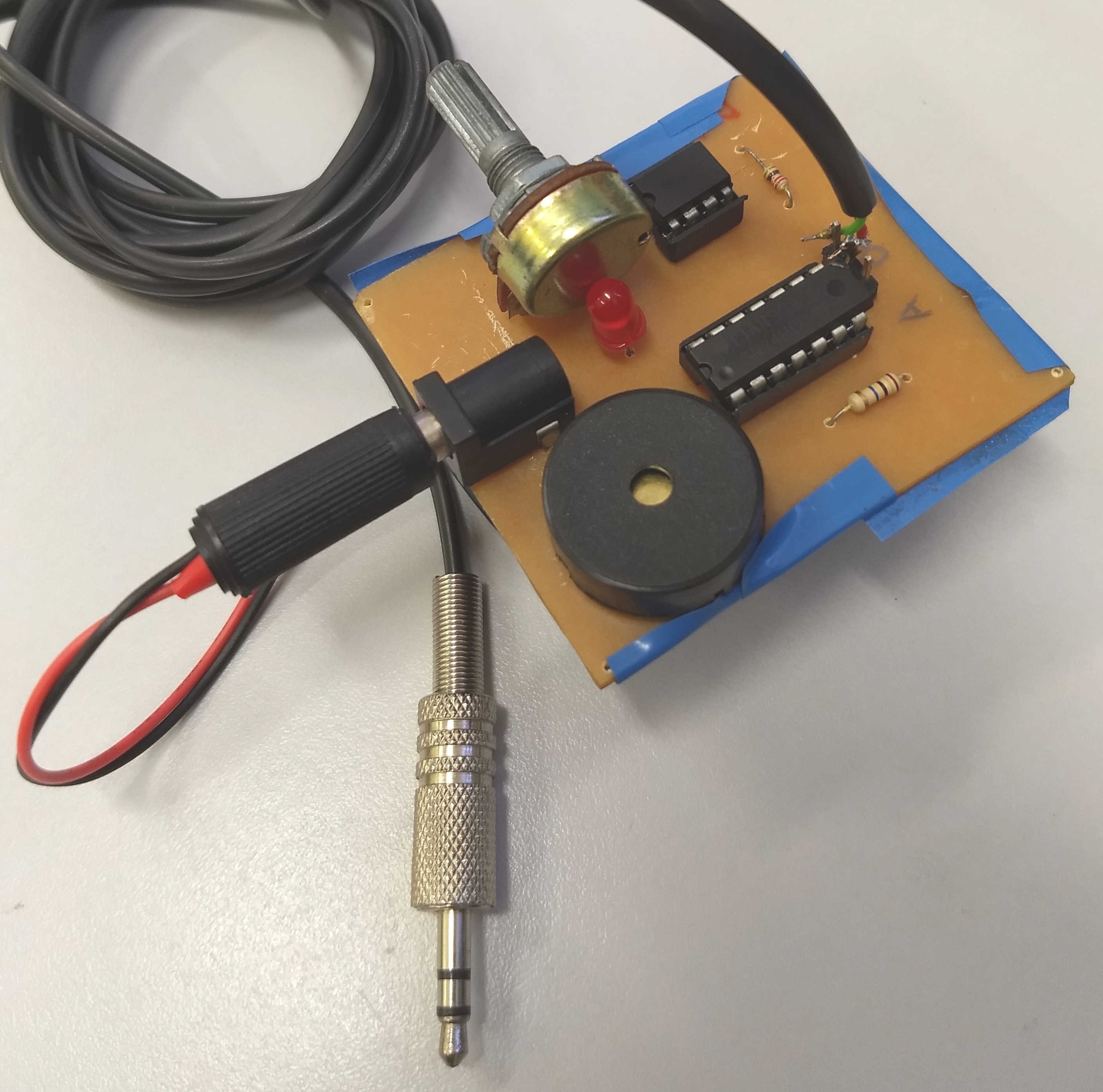
The proposed adaptive switch (AT switch) based on mouth puffing was developed with the intention of being open-source and low cost, so that more people could eventually have access to this tool that can be used as an alternative method for the click of the mouse. The prototype circuit developed in this project is shown below.
![]()
The operating principle of the puff-based AT switch is relatively simple. The perception of the puff occurs thanks to the piezoelectric sensor encapsulated inside a round disc that is placed the top of the device, as shown in the picture below. When the user blows directly into the piezo, there is a mechanical stress that produces a difference in electrical potential at the extremities of the piezoelectric material. Using the voltage produced in the piezo, it is possible to generate a mouse click event on the computer.
![]()
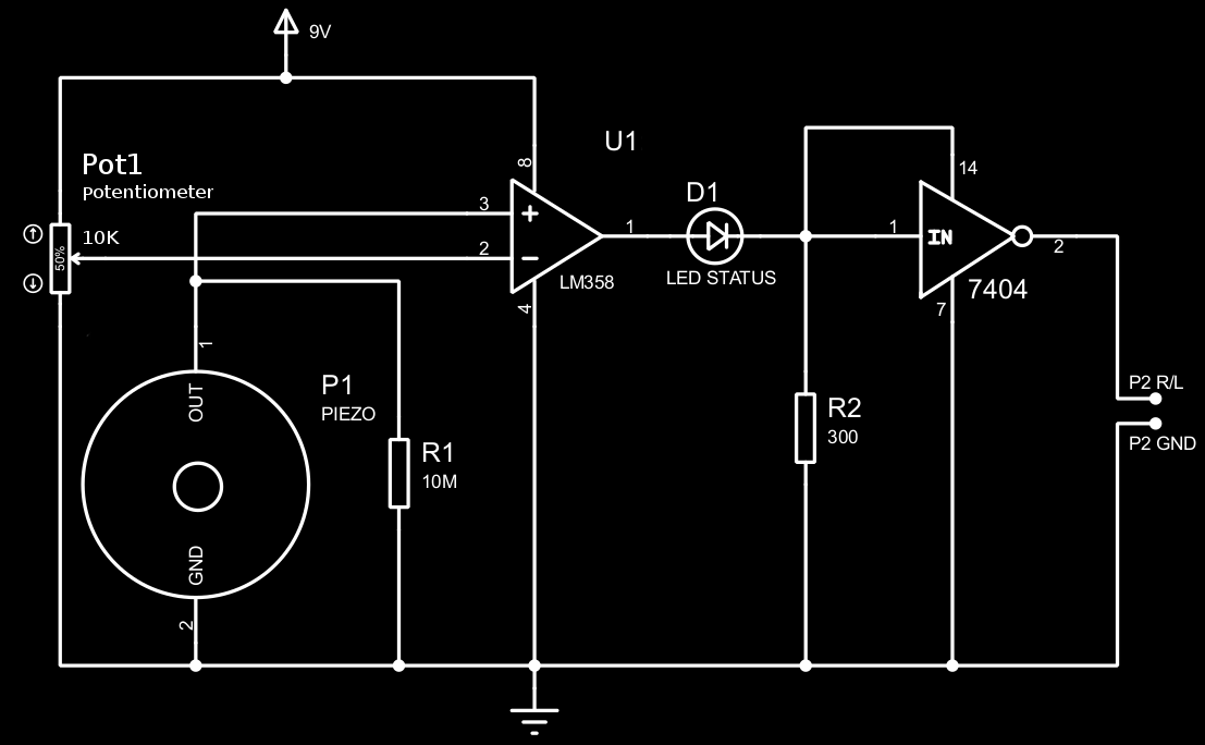
The resistor R1 placed in parallel with the piezo is is responsible for determining the sensitivity that the transducer generates electrical voltage after being subjected to some type of mechanical stress. Therefore, the higher the resistance value, the greater the sensitivity of the piezo. In the developed prototype, a 10 MΩ resistor was used, which resulted in a reasonably good sensitivity. Resistors with resistance values greater than 10 MΩ were also tested, however the sensitivity with resistances greater than 15 MΩ made the transducer very susceptible to detecting mechanical stresses with undesired intensities.
The voltage signal generated at the ends of the piezoelectric material is analog. However, since the mouse click has a binary nature, (click enabled and click not enabled), it would not be possible to directly use this voltage produced as a form of click activation due to the large amount of noise that this signal has. Therefore, the switch output signal had to be digitized.
The solution found to perform the task of "converting" the analog signal from the switch output to a digital signal was to use an LM358 operational amplifier. This electronic component compares two voltages that determine the output of the switch. There is a reference voltage, which can be adjusted thanks to a potentiometer of 10 kΩ, and the voltage produced by the piezo transducer. When the reference voltage is higher than the piezo voltage, the output of the amplifier is close to 0 Volts (low).
However, when the reference voltage is lower than the piezo voltage, the output of the amplifier is close to 9 Volts (high). There is no possibility of the output of the amplifier being different from these two cases. In this way, the reading of the voltage signal produced by the mouth puffing is binary, which facilitates to implement emulation of mouse click events.
Communication Interface with the Computer
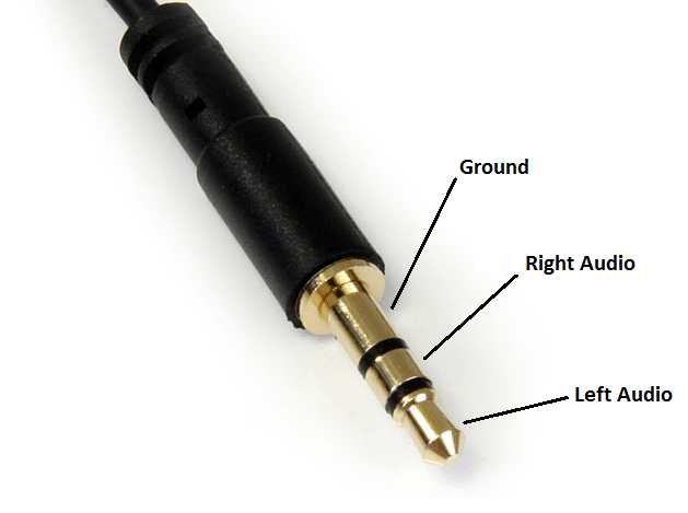
As one of the objectives of the project is to develop an adaptive low-cost switch, communication between the developed switch and the computer is performed with the P2 Jack audio interface shown in the figure below.
![]()
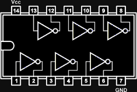
To generate a pulse on the computer's audio Jack input interface, simply connect the GND pin with the Right and Left of the P2 Jack of the switch (short-circuit). For this reason, the use of an inverting logic gate of the SN7404 component, illustrated below this paragraph, was necessary. This logic gate captures the output signal of the LM358 only when it is high, because this very same output is also used to power the SN7404. This voltage is used as the input of SN7404 as well, which in turn inverts the input signal to a low logic level. The inverter output is connected to both P2 Jack's right and left pins, generating a pulse at the input of the computer's audio interface, which is later translated to a mouse click event.
![]()
It is important to note that the output voltage of the OpAmp, when high, is very close to 9 Volts. This voltage is higher than the max voltage recommended (5.5 Volts) by the component manufacturer [Texas Instruments]. To reduce this voltage, a red LED in series with a 300 Ω resistor was used. When the amplifier output is high, there is a voltage drop on the cathode of the LED that is sufficient to power the inverter circuit. Therefore, in addition to being used as a voltage divider, the LED also works as a visual feedback, indicating whether the switch was activated by the user's puff.
A video of the puff-based switch working can be seen below.
-
3Puff switch support
One of the biggest challenges found in the development of this work was to find a way that the user could perform the puffing directly at the piezo. The puff-based adaptive switches available, such as Sip and Puff Switch with Gooseneck, use solutions with PVC pipes, where the person blows through one end of tube to be able to use the switch connected to the other end. However, this kind of solution would require a direct contact of the mouth with the tube, which is not recommended due to hygienic issues.
Some other solutions, such as Orin Instruments Sip and Puff Switch, on the other hand, use a kind of headset to hold the tubes of PVC near the user's mouth. This served as the basic idea for the construction of support developed in this work. Here, annealed wires were used to hold the puff-switch close to the user's mouth. The wires were then coupled on the sides of a headset and were curved in such a way that the ends of the wires were in front of the user's mouth. Two crocodile clip were placed at the ends of the wires in order to couple the device to the holder skeleton. The result of the developed support is shown below.
![]()
With this structure, the switch will always stay in front of the user's mouth, regardless of the position of the person's head. In addition, the status LED is always in the user's field of vision. Therefore, the support does not compromise the visualization of the LED that informs whether the switch was activated or not by a mouth puffing. It is also important to point out that since the headset used has a size adjustment structure, the support can be used by several people, simply adjusting the desired size for each head size.
The proposed puff-based tool was developed to work in conjunction with a software that allows the mouse cursor control through an unconventional method. Head movements captured by a camera are translated to the mouse cursor thanks to the Enable Viacam (eViacam) head tracking software. Apart from being a free, open-source software, the main reason for selecting eViacam is its configurations, which can be adapted to each user.
-
4Jack AT Switch (Audio) Driver
From the beginning, the goal was to keep the project as low cost as possible. Hence, a USB interface was soon discarded, since the communication with the operating system via serial ports is not so easily manageable by analogical hardware prototypes alone. A microcontroller would therefore be needed to allow the proposed device to communicate with the computer, which would increase the production cost.
Inspired by most toys developed by the ATMakers community, and by some AT switches such as the AbleNet's Jelly Bean Twist button, the communication with the computer was implemented via audio jack, also known as P2 or 3.5 mm interface. As already said, tip-ring-sleeve (TRS) audio connector, which typically composes both ends of an aux cable, was used to connect the puff-based device with the computer.
Being the hardware part ready altogether, the proposed device would only be effectively able to communicate with the computer after the development of some software driver. In other words, a USB-like plug-and-play functionality would just not work via audio P2 interface, which means the operating system would not recognize the proposed switches as mouse devices. However, since the single purpose of the jack port on desktop machines is to deal with audio input and output, we could make use of PortAudio library to record audio data and pretend our mouse click emulator devices are a microphone. Since data is transferred to the computer through the sleeve channel, while tip and ring are responsible for receiving the sensed data from the piezo disc; all three channels were short circuited in order to allow the analog information to flow from the sensor into the computer. The click function itself is easily implemented by Xlib on UNIX-based operating systems. A version for Windows is not yet available, since we have been stupid enough to fail at compiling PortAudio on Microsoft's OS. So I suggest you come to the Tux side :).
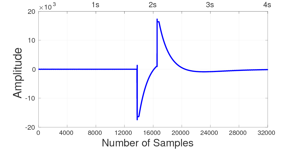
The figure below shows an audio signal recorded during a mouth puffing. PortAudio was configured to record data at 8 kHz on a single channel, with 16 bits per sample. Since their official example for recording audio specifies a time in seconds to capture data from the microphone, a loop was created to record audio for one minute indefinitely, which mimics a circular buffer (the one we were not smart enough to implement :). The voltage change on the piezo is directly transferred to both left and right channels of the TRS connector, which results on a positive and a negative peak observed between the samples 12,000 and 20,000. A threshold based on the energy of the signal was applied to separate a puff from a non-puff when analyzing the data.
![]()
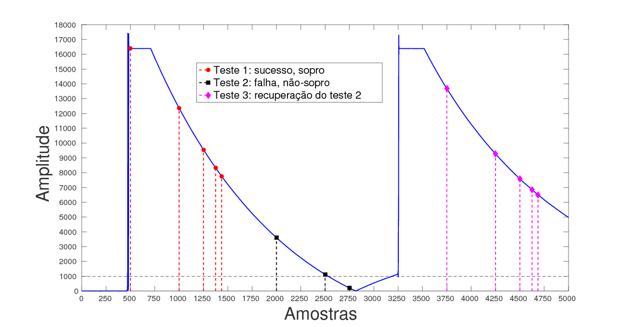
The next figure depicts a practical example of the routine used to identify a proper puff within the audio signal. Basically, the magnitude of the signal was first taken in order to allow us to deal only with positive values. Then a fixed threshold of 1,000 was defined (despite there's an option on the code to calculate the average energy of a initial window of samples recorded from the mic). We analyse the audio from 1,000 to 1,000 samples, which gives us a great precision without wasting a lot of unnecessary time looking at every audio sample.
Let's go to the practical example. Let's say the first element of the window is the sample of number 500, as shown by a red circle marker on the figure (teste 1); which is above our pre-defined threshold. Therefore, instead of looking 1,000 samples ahead (x axis 1,500), our algorithm will look at sample number 1,000 (a half-step). The current sample is also above our threshold, so we'll again divide the step window by two. So we'll keep analyzing samples number 1,250, 1,375 and 1,437. Since the latter is our 5th sample above the threshold in a row, the algorithm identifies that as a puff, performs the click with X11 routines and skip the next 8,000 samples (i.e, is stays idle for 1 second).
![]()
But what if we detect a sample above the threshold almost in between the two peaks of our audio signal? Now we're talking about test 2 squared markers, in black. Let's say the algorithm catches the first sample above the threshold at sample number 2,000 (x axis). At the third check, now at sample number 2,750, the algorithm will find a value below the threshold, so it will consider the two previous samples above as noise. The window step (which would be 1,000/2/2=250 by now) is then restore to 1,000 and the algorithm continues its normal course at sample number 3,750 (test 3, on the hexagonal-marked, magenta-colored lines). Thanks to the second peak captured by PortAudio, the algorithm would now be able to find five samples above the threshold in a row at 3,750, 4,250, 4,500, 4,625 and 4,687.
DIY Low-cost AT Switches
Low-cost, homemade AT switches that, unlike Jelly Bean buttons, work by many forms rather than by contact or pressure
 Cassio Batista

Discussions
Become a Hackaday.io Member
Create an account to leave a comment. Already have an account? Log In.
May be you could consider using LM393 Comparator. It has open collector output that you can pull up to 5V for driving your logic circuit input directly (not power pin!) So you can get rid of the mickey mouse logic.
Are you sure? yes | no
Hi, Lee. Thank you for the tip. Do you have some (or any) kind of material about that to read? We're not really taught about the differences between OpAmps used as comparators and actual comparators. To be honest I myself have not even the heard the term "mickey mouse logic" until now :(
Are you sure? yes | no