pastcompute
-
PCBs and Circuits!
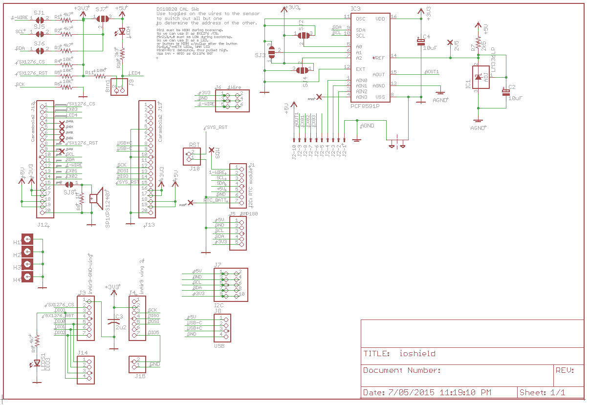
05/08/2015 at 03:01 • 0 commentsSo we won a OSHPARK voucher. Thank you Hackaday and OSHPARK! I guess there is quite a bit of lead time, so now I put together a circuit for an I/O shield for the Carambola2, most importantly with a breakout for the inAir9 RF module.
![]()
I have actually made it quite generic to allow flexibility. It has specific connections for an i2c RTC module and a BMP180 barometer I already have, 1-wire connectors, and expansion for more i2c things and GPIO, and an onboard PCF i2c ADC. Because I might want to swap things around I have made pullups and i2c addressing configurable
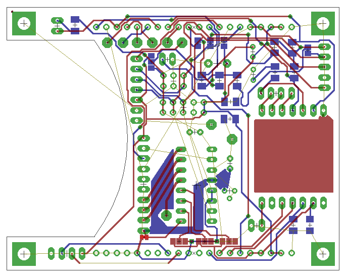
The PCB is still a work in progress, its not finished yet...
![]()
This will be fine for the farm station, but the other end I am still thinking over the design.
I really want to have an embedded Linux module in the fence post sensor for power and flexibility, but I think something like, say, a Teensy LC would be useful to slave off all the sensor readings to...
-
Fencepost / Home base prototype
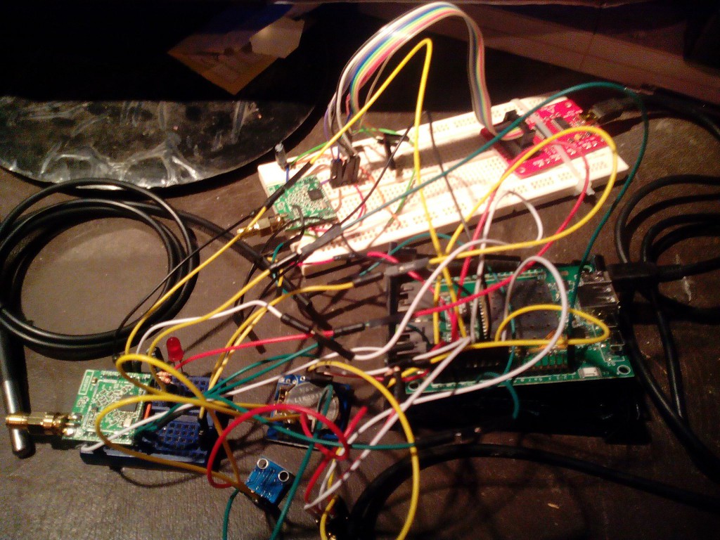
04/29/2015 at 13:41 • 0 commentsSo, inside the birdsnest are two systems:
(1) bus pirate and SX1276 inair9 LoRa module
(2) Carambola2, SX1276 inair9 LoRa module, bmp180 barometer, DS18B20 temperature, RTC, etc.
![]()
I realised that I can write code in binary mode to drive the bus pirate, which means I can write software to run on a laptop to pretend to be the farm base. Although as a diversion I managed to write code that claims to compile into 1020 bytes for an ATtiny13 to act as a serial - SPI bridge :-) I just need the ATtiny13 to rock up in the mail so I can see if it actually works!
I also managed to get SPI over GPIO working on the Carambola2 as the fencepost station, to talk to its SX1276.
So for a while now there should be more software going on than hardware, although I need to do something about the birdnest so I can put a module out in the paddock. Hmm, a circuit board might help here...
-
Could I build an ATtiny13 to SPI bridge?
04/26/2015 at 12:20 • 0 commentsConcept: Laptop or Android tablet --> USB - Serial adaptor <--> ATtiny13 at 3v3 <--> SX1276?
The BusPirate will let me play with the SX1276 registers and do some initial set to work, but even using macros or the built in Basic will get a bit tedious for more serious stuff. The first proper fencepost station will have a 3v3 Carambola2 but its not really useful for portable debugging. When we get to building and tweaking antenna and trying to get range, it will be handiest to be able to hike around with my trusty AspireOne or a tablet...At around $1.20 I may as well buy a couple and see if it is possible to cram a very simple serial port register translation and data transfer protocol into 1k of flash!
-
5v, 3v3 --> Bus Pirate of course
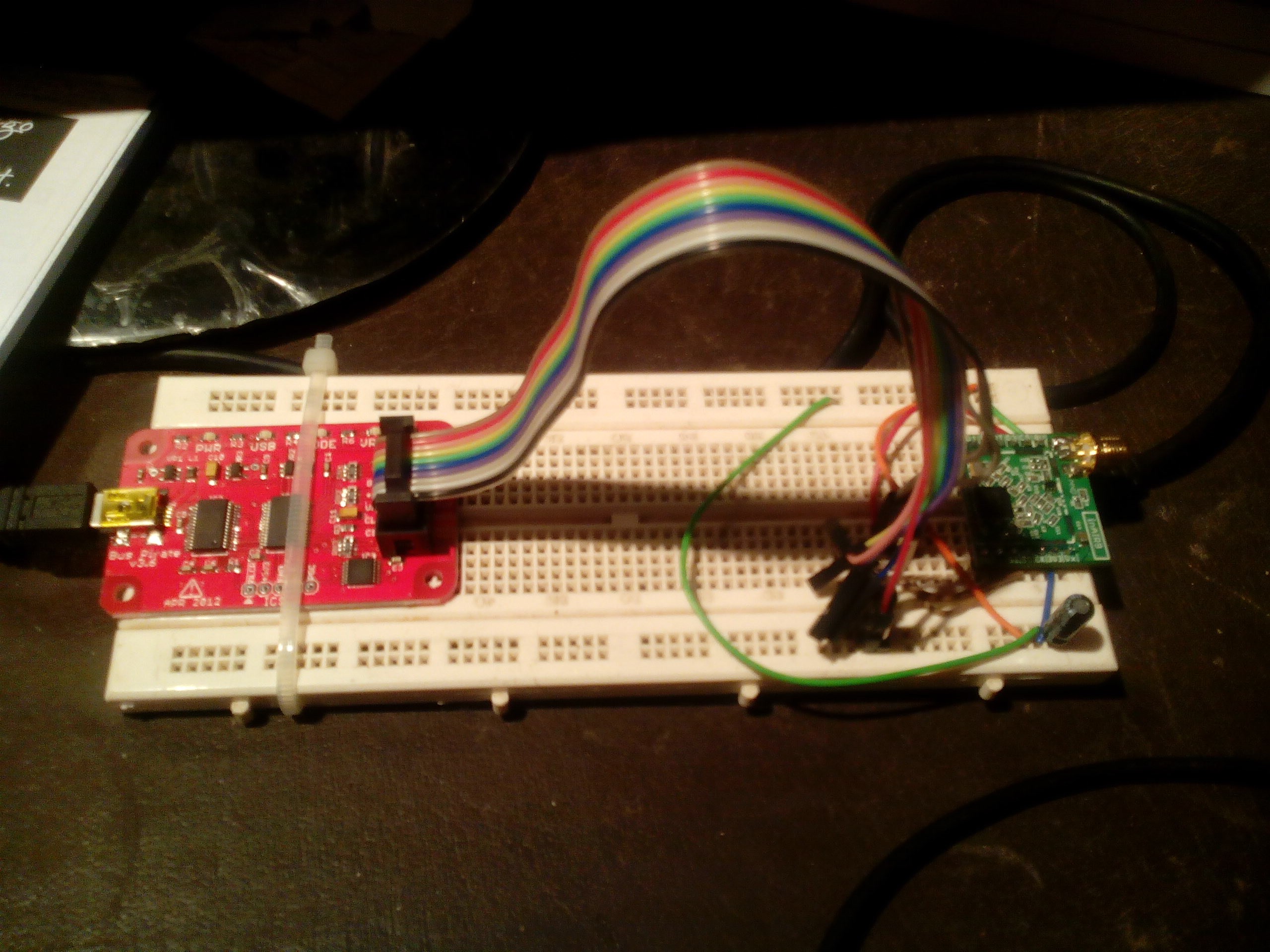
04/26/2015 at 09:22 • 0 commentsSo of course the Digispark needs 5V as I rediscovered when I went to wire it up. I had always run it on USB power until now, and unlike some of my other gadgets it doesn't have a 3v3 converter. Well, it is small. I don't have any spare level converter boards and don't want to wait.
Then I remembered my Bus Pirate. Problem solved...
![]()
(Update)
So the bus pirate is working well. (Apart from only having one...)
picocom -b 115200 /dev/ttyUSB0

im5 1 1 2 1 2 2
Wva%:6A
[0x42 r:1][0x01 r:1][0x02 r:1][0x03 r:1][0x06 r:1][0x07 r:1]
This produces SPI reads that match the default values in the datasheet. Seeing as this is the first time I ever used SPI , this is a win :-)/CS ENABLED WRITE: 0x42 READ: 0x12 /CS DISABLED /CS ENABLED WRITE: 0x01 READ: 0x09 /CS DISABLED /CS ENABLED WRITE: 0x02 READ: 0x1A /CS DISABLED /CS ENABLED WRITE: 0x03 READ: 0x0B /CS DISABLED /CS ENABLED WRITE: 0x06 READ: 0x6C /CS DISABLED /CS ENABLED WRITE: 0x07 READ: 0x80 /CS DISABLED
This could get quite involved, so I might set up a separate place to write about it. -
Various things
04/25/2015 at 15:50 • 0 commentsI finally got some time to finish the software and do a v0.1 ground station. Its based around the ESP-01 still because I will need to spend some time working out the circuit board layout for the ESP-07, so at the moment I'm not logging solar voltage, etc. I'm hoping to build it into a suitable box tomorrow and deploy it in the back yard. I've retasked a TPLink router using OpenWRT that is currently receiving logs from the build on my desktop :-) I'd hoped to get there today but I ended up spending some time working around a possible SDK bug in deep sleep mode, which I seem to have resolved successfully.
![]()
Along the way I actually came up with some ideas to really squeeze out the ESP-01. Once things are really bedding down I wont need the serial RX pin so that can be retasked; so at that point could put an I2C ADC on the RX and GPIO #2, so things will get interesting for a variety of projects...
More importantly, my inAir9 SX1276 LoRa modules arrived.
So while the ground sensor is chugging away, I will be working out how to use the modules so that I can then build a proper fencepost relay station.
I think I may have a use for my Digisparks. I think they have just enough pins and memory that I can use them to make a bridge from my laptop USB to the SX1276 SPI connection so that I can build up some software in Linux and come to a good understanding of their performance in relative comfort.
The LoRa modules will provide the 10km+ link so they form the critical path at this stage. It will be easy enough to integrate the sensors for rainwater, wind etc later on.
-
Experimentalist musings
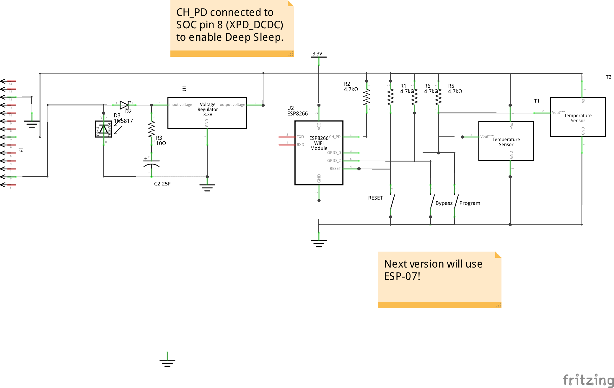
04/17/2015 at 14:35 • 0 commentsI figured I'd measure my ESP8266 test system, so I scrounged a 1Ω resistor and estimated the average current at 70mA, i.e. 230mW, even when just sitting on a timer. This is more than the solar panel at peak, and no amount of MPPT will help us with this, so luckily the ESP8266 has a deep sleep mode which various people have estimated < 50μA, or 165μW. Downside is until my packages get here I'm stuck with an ESP-01 which will require some precision soldering to enable deep sleep...
In the meantime I took a closer look at my logs. Occasionally analysis is no match for experimentation but I might as well do some predicting, as well as confirm previous hypotheses.
- There are times the solar panel voltage drops below the regulator input / supercap when the supercap still has a few 100mV of capacity and was below its earlier peak, which means energy is just getting wasted. Effectively at those times the panel is reporting open circuit voltage which is good for a daylight metric but not much else. All the while the capacitor is discharging through the regulator.
- This would be much less of a problem with a AA cell as there is a less direct relationship between voltage and charge.
- I really need to hook up a load and log that for a while, because really all I have proved is I can log some data and that 22F will keep an unloaded 3v3 supply up overnight which isn't that useful by itself
A combined MPPT / boost circuit would help with the wasted sunlight: varying the switching to track peak power of the panel, efficiently regulating to 2.4V to 95% utilise the capactor, followed by a step up to 3V3... but thats starting to sound a little over complicated.
Of course, I could revert to a AA rechargable, but that would be less interesting to me at this point. Rechargeables need maintenance: eventually they need replacing and likely to die at an inconvenient time. They also do cost a lot less.
So back to the back of the very rough envelope: lets assume a rather bad efficiency of 25% and 8 hours daylight, then 2.5V @ 0.02A x 6= 300mWH, and if we use 60s/hour for reading sensors and transmitting and assume 200mA in that small work period then the approximate power required is (.983 * 165μW + .017 * 0.2 * 3.3) x 24 or 273 mWH so we have 10% margin even at those extremes.
I should have done that calculation more explicitly before, luckily it works out OK. But regardless, to date this has been useful as an exercise for getting my lab back into shape and getting my mind back into the swing of working with electronics.
-
Another update
04/16/2015 at 13:00 • 0 commentsWell I've been busy with other things. After talking to other people I'm still thinking I'll use the ESP8266 in the sensors, but I am probably going to build a head to head ESP8266 vs. Arudino Micro plus NRF24L01 and see how they go against each other.
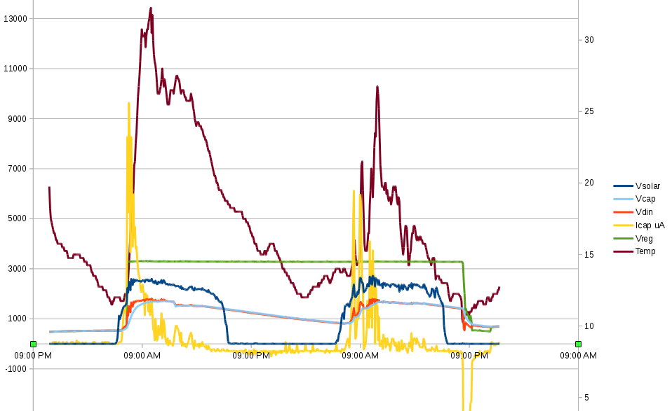
I also manage to process some log data from across last weekend. As usual it seems obvious with hindsight, buy very obviously having the temperature sender inside the plastic box with the electronics acts as a bit of a glasshouse, and you can see the temperature spiking up to 35C on a day when outside never got past 25C. This seems to be actually interfering with voltage regulation interestingly, the output drifts as high as 3.6V (unloaded, still) once the supercap is fully charged. On the plus side, even once I hook up the ESP8266 it looks like the 22F capactor _should_ hold enough charge to do what I need overnight and still recharge on an overcast day, although the jury is still out. I'm intending to hook that lot up on the weekend, as I finished a first cut of the sensor software, which itself logs its own VCC and a DS18B20 using an ESP-01.
![]()
I cant remember if I mentioned it, but I am also playing with designs for a solar MPPT charger front end although that may be gold plating if things work OK as is.
-
Welcome Update
04/10/2015 at 11:37 • 0 comments@plains203 my neighbouring farmer has joined the project now.
He showed me a quick google maps survey, there are more than 10 large paddocks, several geographically separated with the longest shot over 10km.
The benefit of this project will extend way beyond just weather monitoring, because the more any farmer can learn about crop conditions the better, and a continuous remote data logging solution will provide great value in this regard.
So all we need to do is solve the 10+km shot first !
-
Logging shenanigans
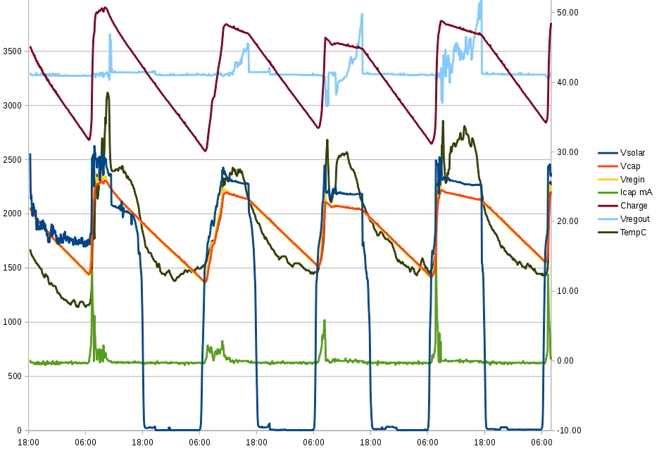
04/10/2015 at 11:29 • 0 commentsCatching up, I ran the logger over two days and nights.
The first night, the supercap slowly discharged, and maintained (unloaded) regulator voltage.
The second day was rainy / overcast, then at around 8pm suddenly the current out of the capacitor surged and the regulator voltage collapsed. This version of the chart doesn't show capacitor charge which is proportional to the voltage but it lost 33% in 1/2 hour as well. Notably the temperature dropped very sharply, 2C in 30 minutes, but I suspect what actually happened is some moisture shorted out something.
![]()
So apart from using more rubber bands, I had reinforced what was obvious, that the system is underutilising the capacitor by a good third.
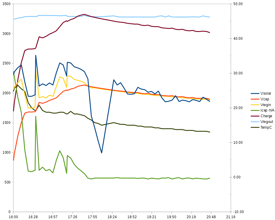
So this evening with about two hours of daylight left after work, I replaced the current limiting resistor with a 39 ohm (was 68) and shorted out the 1N4148 leaving just the shottky diode.
Preliminary chart results:
![]()
As expected, things are somewhat better (even at this early stage)
By 8:30pm the capacitor retains 50% more charge compared at the same time of day to the first test.
Obviously, the capacitor recharges at a much faster rate; recovering from 15% to 80% eventual charge in 35 minutes full (late afternoon) sunlight, versus 30% to 80% eventual charge in 1 hour 20 full morning sun in the first configuration.
I seem to have a short somewhere, because it is night time, the solar graph should be 0 at this point... <strikethrough>Note, the sharp drop and recovery is where I had the panel positioned so that it fell under shade of a large tree, and I moved it back into the sun.</strikethrough>
-
Brief update
04/07/2015 at 12:37 • 0 commentsMore on this later, but one obvious thing is that with the MSP430 using two diodes to drop around 0.8V off the panel, presumably to allow trickle charging of a normal battery, is that only 1.6V max charges the supercap. With peak charge Q = CV and supercap rated to 2.5V an extra 50% energy could be retained by allowing 2.4V on the supercap instead of 1.6. So the next mod will be to short out the 1N4148 and leave just the shottky diode, if I can confirm the resulting voltage will always be < 2.5.
SentriFarm
Solving a key farming problem: is it safe to harvest / spray / sow today? (+experiments with 'big' data in agriculture)