
Micro:Gamer
Portable game console based on the Micro:Bit
Portable game console based on the Micro:Bit
To make the experience fit your profile, pick a username and tell us what interests you.
We found and based on your interests.
That's it, I don't have much more to say :)
A couple months ago, given the feedback I received on the project, I decided to order a batch of 20 Micro:Gamer from Seeedstudio. They are now available on Tindie.
The hardware is 99% the same as revision B, I only moved some components by a few millimeters and added more decoration on the silk screen. Also the PCB is now red!
On the software side, the Micro:Gamer library is integrated in the Arduino library manager. So it is even more easy to start programming.
I just received the first batch of Micro:Gamer rev-B from SeeedStudio. It is the first time I have a design made in series, a very small series but a series nonetheless :)
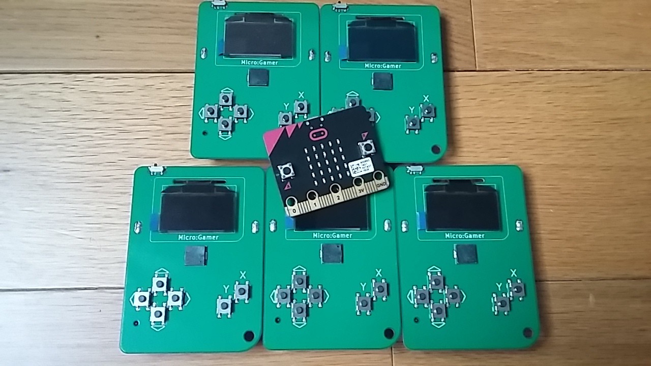
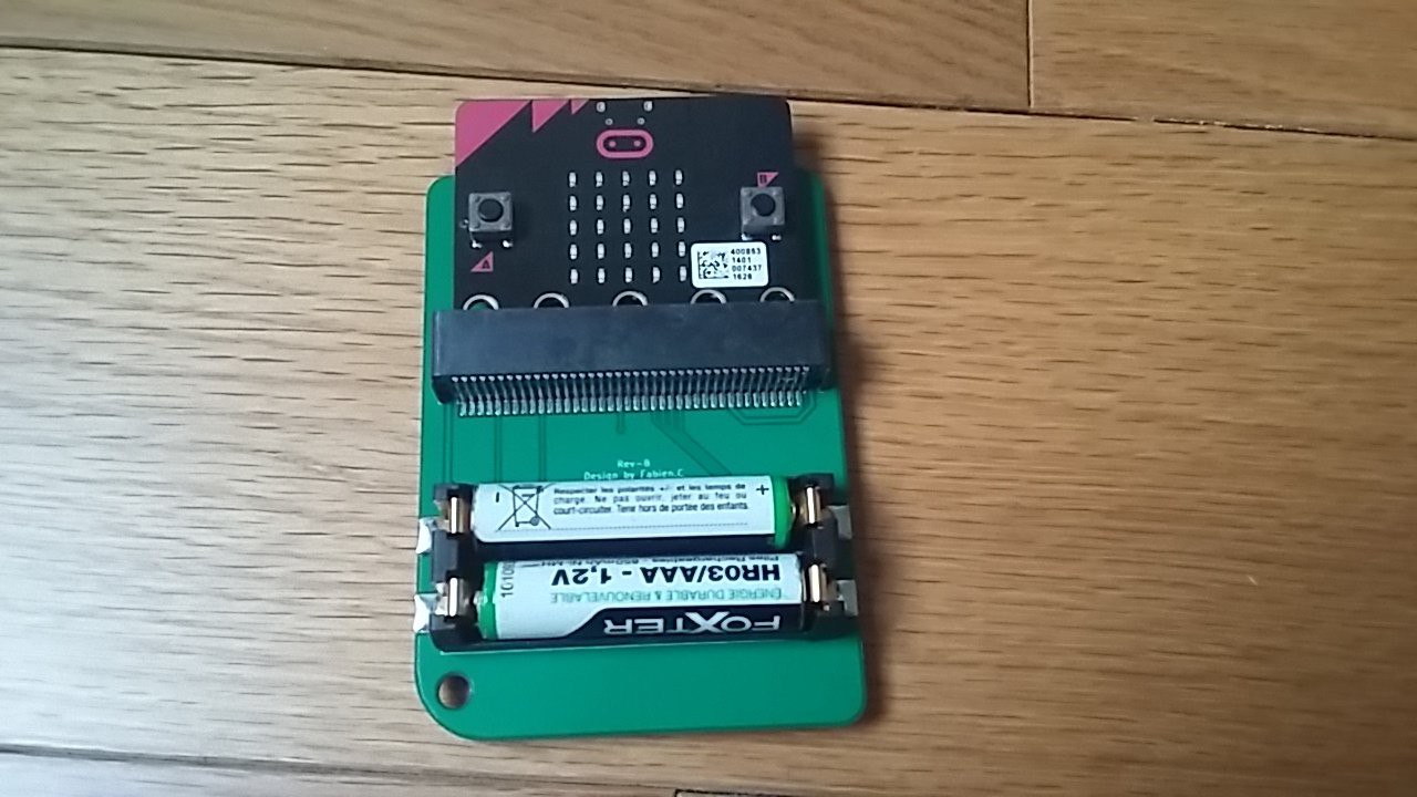
There's a few changes in the design, the first one being the SMD version of the micro:bit connector which allows for a better looking board. I also added a power slide switch and slightly moved some components.
As stated in the title of this post I'm giving away 4 of the boards. I have no use for 5 so if you have a cool idea for a game or feature that you want to try, I will be happy to send one to you (depending on the how much it costs, I might ask you to pay for shipping). Contact me using the private messages if you are interested.
I think it is time to do an update on the DODO list:
New item:
On the Micro:Gamer, the OLED screen is controlled via an I2C bus.
The screen resolution is 128x64, that is 8192 pixels. Since the screen is monochrome, there is only one bit per pixel so the frame buffer size 1024 bytes. We have to transfer all those 1024 bytes over I2C to refresh the screen. Lets calculate how much time it takes.
I2C transfer time
First we have to count the number of bits in an I2C transfer.
- 1 start bit
- 8 address bits
- 1 address ack bit
- 1 stop bit
- 8 bits + 1 ack bit for each byte of data we transfer
So the total number of bits for a transfer of N data bytes is:
bits (N) = 1 + 8 + 1 + N * (8 + 1) + 1
or
bits (N) = 11 + (9 * N)
Then we can calculate the speed of the transfer by dividing the number of bits by the speed of the bus in bits per second.
The micro:bit is fitted with an nRF51 microcontroller. On the nRF51 the maximum speed of the I2C controller is 400k bits per second, so the transfer time is:
transfer_time (N) = bits (N) / 400000
For examples, transferring 10 bytes will take
transfer_time (10) = (11 + (9 * 10)) / 400000 = 0.00025 seconds
or
0.25 milliseconds
There are more things to take into account for an accurate estimate of the transfer time, but this is a good approximation.
Arduino library I2C transfer
Now that we have the formula, let's see how much time it takes to transfer the 1024 bytes of our frame buffer.
The Arduino library limits the number of bytes per I2C transfers so the frame buffer has to be sent in multiple transfers. The driver I used, from Adafruit, sends 16 bytes of frame buffer per transfer with an extra byte to specify that we are sending data for the frame buffer, which means 64 transfers of 17 bytes.
So the total time it takes to send the full frame buffer is:
64 * transfer_time (16 + 1) = 26.2 milliseconds
The Arduino library driver is implemented using the polling technique. The CPU just continuously waits in a loop until it can send the next byte. So during the transfer time, the CPU is doing almost nothing.
If we want to run a game at 30 frames per seconds - one frame every 33 milliseconds - a transfer time of 26.2 milliseconds means that 80% of the CPU time will be wasted in I2C transfer. This is not ideal...
Asynchronous frame buffer transfer
The solution to this it to let the CPU do something else during the frame buffer transfer, and it can be done with interrupts. So I implemented an interrupt based I2C driver.
The CPU sends the first byte on the I2C bus and then continues its work, typically it will start to compute the new state of the game and render the next frame.
When the I2C controller is ready to send the next byte, an interrupt is triggered and the CPU will temporarily stop its normal operation to send the byte.
As a result, there's more CPU time available to execute the game code, allowing more complex games to run on the Micro:Gamer.
Double buffering
One potential problem with asynchronous frame buffer transfer is that, as the CPU continues to execute the game code, it can override the frame buffer in the middle of the transfer. This can cause glitches on the display, similar to the rolling shutter effect of digital cameras.
Again there is a solution for that, double buffering! Using two frame buffer instead of one, the CPU can edit frame buffer A while sending frame buffer B, and then it is the opposite, CPU edits frame buffer B while sending frame buffer A. Of course this means that we have to allocate one more frame buffer so it has a significant impact on memory usage.
After the persistent data storage, the next important feature for me was sound.
There is a small buzzer on the Micro:Gamer board which means it can play a single note at a time. It is enough to play little tunes and some sounds effect as shown here:
This time again, I re-use the Arduboy libraries to provide compatibility with the existing games.
Most of the games I ported from Arduboy to the Micro:Gamer use EEPROM to save high score or game state when the console is powered off. I think this is must have feature for a game console so I implemented it for the Micro:Gamer.
There is no EEPROM on the micro:bit board and I don't want to add it as an extra component on my hardware design, so I had to use the flash memory inside the micro-controller.
The interface to use the flash as persistent storage is provided by the MicroGamerMemoryCard class. This class uses two different memory areas:
Here is an example of how it looks like in the code:
// Create a memory card of one 32bit word
MicroGamerMemoryCard mem(1);

// Load the content of the flash page to the temporary RAM buffer
mem.load();

// Read a value from the temporary RAM buffer
if (mem.read(0) != 42) {

  // Write a value to the temporary RAM buffer
  mem.write(0, 42);

  // Permanently save the RAM buffer into flash memory
  mem.save();
}
And here is a demo with the game Micro City:
Like most of you I suppose, I love the micro:bit. It is very affordable, available everywhere, quite powerful and it even has an integrated programming/debugging probe. However, one “disappointing” aspect in my opinion is the 5x5 LED matrix. It can barely display text and cannot be used for anything beyond very very simple “games”. A couple months ago I saw the Adafruit OLED Bonnet for Raspberry Pi and I thought it would be cool to have something similar for the micro:bit, so I decided to give it a try.
One of the design choices for the Micro:Gamer is to embrace the micro:bit edge connector. There are a good number of disadvantages with this connector, it’s big, there is no SMD version (at least I couldn’t find one). But for this project in particular I think it is great because it mimics the cartridge of a retro console like the GameBoy. If you have more than one micro:bit you can program different games and swap between them.
For the batteries, my first idea was to not include any on the board (keep it simple), but then it’s not really a portable device anymore… The next choice was between a coin cell battery and 2xAAA. I decided to use the AAAs because - even if they are bigger - it is easy to find rechargeable ones.
For the software I use the Arduino IDE and a modified Arduboy2 library. Since the Arduboy and Micro:Gamer have the same screen and buttons, it is very easy to port games from the Arduboy to the Micro:Gamer (I already did 6). I will maybe experiment with Python support and probably Ada as well.
The next steps for me are:
That’s it for the first project log. Let me know in the comments what you think about this project.
Create an account to leave a comment. Already have an account? Log In.
Hi.
Can you please let me know which microbit pins you are using for the A and B button?
Just playing with this on a bit of breadboard at the moment and I can get all but one of the buttons to work.
Thanks
Hi, you can find the button pins here: https://github.com/MicroGamerConsole/MicroGamer-Arduino/blob/5004d57972767458e9aa8e4c0283ee20f08147bd/src/MicroGamerCore.h#L54
one note about the buttons: they are unconfortable. you should look for silicon buttons.
That is so great! Something I was looking for actually. But I have a suggestion, if I may :-)
I've read that the project uses almost all pins, but the pins for 5x5 LED matrix as well? Would you consider in another iteration to turn the microbit to face forward, so that the LED matrix is visible and usable to the user?
Would be soooo much cooler :-)
It's very interesting and a wonderful project.
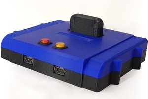
I got it last week and tried making a case, box shaped prototype.
https://www.thingiverse.com/thing:3420712
Nice project, Will you open source the hardware spec? or will you sell this product?
Super project! I am an Arduboy fan and also love the micro bit. Would be great to see an old multiplayer classic like maze war / maze wars+ running on this which could use the micro bits radio feature to send messages to other micro bits.
Love this project! I am a regular on the Arduboy community, and you have inspired me to order a micro:bit!
Would you be able to share the pinout for how you have everything hooked up to the micro:bit's edge connector? I could dig through your fork of the library to figure it out, but thought it would be easier to just ask... 😃
Well the sources actually hold the most reliable information right now :)
Here are the locations of the different pins:
- I2C : https://github.com/MicroGamerConsole/MicroGamer-Arduino/blob/master/src/Arduboy2Core.cpp#L86
- Screen Reset: https://github.com/MicroGamerConsole/MicroGamer-Arduino/blob/master/src/Arduboy2Core.h#L42
- Buttons : https://github.com/MicroGamerConsole/MicroGamer-Arduino/blob/master/src/Arduboy2Core.h#L52
- Buzzer: https://github.com/MicroGamerConsole/MicroGamer-Arduino/blob/master/src/ArduboyTones.cpp#L59
(The pins might change with next revisions)
If you have an Idea for the Micro:Gamer let me know here or in private message. I will receive 5 new boards soon and I plan to give away 2 or 3 for some motivated contributors.
@aldolo some of the files were renamed: https://github.com/MicroGamerConsole/MicroGamer-Arduino/tree/master/src
Are you planning on selling this? If so, do you have an estimate of how much it would cost?
I would love to make a product from this project. I'm working on it, I will let you know when I make progress.
Do you think you could get the wireless working? It seems to me the most interesting games would involve large numbers of Micro:Bits and wireless interaction. Maybe not real time gameplay, but some sort of social aspect.
It's definitely possible to use the wireless feature of the micro:bit but I didn't try that yet. Right now I'm focusing on core features and hardware design.
As for the kind of games that could be done, I want to try real-time 1v1 games at least, for the rest I count on your imagination ;)
At first this seemed a bit pointless, since Arduboy already exists. But then I noticed you're using the Micro Bit. That changes it! There's probably a lot of kids who'd be much more interested in the MB if it had features like these.
The fact there's games already available helps too. Particularly cos kids can play them, have fun, then, the crucial step, start modifying them and seeing what happens. That's always a good start.
Is it open source? I know the parts are fairly cheap. It'd be great if this takes off for schools. It probably won't, but that's more their failing than yours. Still parents might be interested. Or kids, and for the price it won't be hard to badger a parent into buying it.
Just one suggestion... might it be possible to leave the 5 big hole connectors available? I realise the connector blocks them. But if that can't be changed, maybe have breakout points on the board? You could even just do them as PCB pads, and let the owner drill through if they want to. Should do the trick I think. Don't think it'll need through-hole plating, especially if you connect both sides together.
Then a kid could have lights flash, or whatever else, when they score points. Or make their little robots more interactive.
"Just one suggestion... might it be possible to leave the 5 big hole connectors available? I"
I'm using almost all the pins of the edge connector so the 5 big hole connector will not be available for the users.
I will probably post them but at least I need to clean it before :)
I have small group of kids in orphanage, teaching them programming since last year.. soon i'l introduce some basic electronics for their age.. and good thing we do all on micro:bit's so it would be cool if you share it, i would most likely add their names on PCB and teach them how to solder it, some ideas how some product is born.. i see that it's quite simplified, so i would not bother them with much caps, resistors and others parts.. would be interesting i think...
that is why i'm asking :D
@nardev This project is not suitable for teaching soldering, especially for kids. It uses small SMD parts and the screen's flat flex is also quite difficult to solder.
don't worry, it will fit... it doesn't have many parts...good enough. It would definitely not be the only thing they do.
Nice one. You might like my project too: #Bit:Boy I attempted the same a couple of months ago. Apart from Arduboy, I have Gamebuino emulation in place and I was experimenting with Bluetooth to play games on your phone and stuff.
Awesome, I love how you use the micro:bit as a remote controller!
You just got blogged about at https://hackaday.com/2018/02/27/microgamer-is-a-microbit-handheld-console/
Very nice! Making the library fit an existing one and thus leveraging an existing community and their games makes a lot of sense when you just want to play games on it.
The micro:bit is more capable than the Arduboy so this is just a quick solution to get started. There's a lot more to do with the on board accelerometer, magnetometer, the increased RAM size and CPU power.
Hi, great to see you starting work on this! You might be interested in my recent attempt at the same: #Micro:Boy
Thanks! Actually my first prototype was called Micro:Boy until I saw your project this week :)
I will post project details when I get the next board and you will see that we took different approaches.
Become a member to follow this project and never miss any updates
 Nicola Wrachien
 Albert Gonzalez
 Clyde Shaffer
 Jim Shortz
Sorry it would be X and Y buttons.
Thanks.