 Blair Wyatt
-
1Step 1
While the SubPos Nodes make it easier to set up positioning and provide additional features and a USB to UART converter built in, SubPos can be set up with nothing more than ESP8266 modules, a smartphone, USB to UART converter and a power supply for the ESP modules. You can even operate the ESP8266 module with SubPos enabled (AP mode) and as a Wi-Fi client at the same time! You can even use the NodeMCU module if you would like similar functionality to the Node (USB interface and power). The setup commands will slightly differ for the LUA based firmware, but they work just the same. Or you can load the AT firmware on these modules.
Go to step 2 then 8 if you want to configure a SubPos Node.
-
2Step 2
Determine the GPS locations that correspond to the physical location of the ESP modules/Nodes (by any means, measuring stick, compass, best guess). Use Scribble Maps to help you determine these coordinates (you can easily draw map overlays and get GPS coords from points).
![]()
You can export the KML of the overlay and get the GPS coordinates from the KML document:
![]()
-
3Step 3
Connect the ESP module to the UART converter and power supply using the standard AT firmware, and plug the UART converter into a PC.
-
4Step 4
Encode the ESP module position from step 2 using the Javascript position coder. You will need to enter the following into the invalid chars box as the ESP module doesn't support these characters:
0a 0d 22 2b
The ESP8266 module should transmit beacon frames at a power of 19.5dBm. Path loss values can be obtained here (choose the value from the selection column which corresponds to the environment). The coder will return a hex value.
-
5Step 5
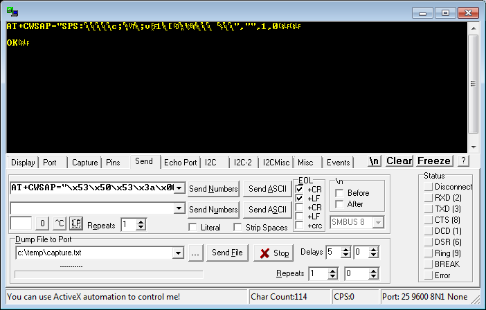
With the hex value from the previous step, you should use it to form the following string:
AT+CWSAP="[hex_string]","",[channel_num],0For example:
AT+CWSAP="\x53\x50\x53\x00\x00\x00\x00\x00\x00\x00\x00\x00\x00\x00\x00\x00\x00\x00\x00\x00\x03\x68\x00\x00\x00\x00\x04\x00\x00\x00\x00","",1,0Enter this string into a terminal application that allows you to enter hex values like Realterm. Check the EOL boxes like shown:
![]()
Now click Send ASCII. The ESP modules will store this setting automatically to flash.
-
6Step 6
Place the ESP modules in the position they correspond to and connect them to a power source.
-
7Step 7
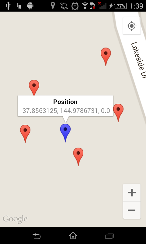
Install and start the SubPos Monitor app - https://github.com/subpos/ssid_coder/tree/master/android-app
It should start showing the position of the ESP modules and also calculate your current position:
![]()
-
8Step 8
Alternative SubPos Node Config
If you have a SubPos Node, plug the Node in via USB and open a terminal application with any baud rate settings. Type help to show the menu and type wizz to use the wizard config. Follow the prompts to configure the Node and once finished, type wree to save configuration to EEPROM.
Once configured, place in it's corresponding position and power it via USB.
The SubPos Nodes will soon support remote configuration too. This mode will allow you to configure a Node via a simple Android application while pressing a button on the corresponding Node.
-
9Step 9
SubPos is now configured and ready to serve positioning information!
SubPos Positioning System
A "dataless" Wi-Fi positioning system that can be used anywhere GPS can't.


Discussions
Become a Hackaday.io Member
Create an account to leave a comment. Already have an account? Log In.
Your link to obtain the path loss values should be updated, it's now on the wiki here: http://wiki.subpos.org/index.php?title=Path_Loss_Calculation
Are you sure? yes | no
Awesome!
Are you sure? yes | no