Blair Wyatt
-
What's Going On
10/22/2015 at 06:56 • 0 commentsI haven't stopped the project, I've just been fixing a few small issues here and there.
The Android API has an improvement on the trilateration code. It converts coordinates to meters using Mercator projection for trilateration and then back again for better distance calculation. Plus a few other improvements.
The Node hex firmware has had a few bug fixes.
The SSID Coder has had a few bug fixes too.
I will also be presenting a SubPos tutorial and demo at the Open Source Developers Conference next week and Buzzconf in November.
There are lots of things in the background at the moment too which should have more info in about 3-4 weeks.
Stay tuned!
-
Revision 03 Nodes
08/26/2015 at 15:04 • 0 commentsUpdate 3:
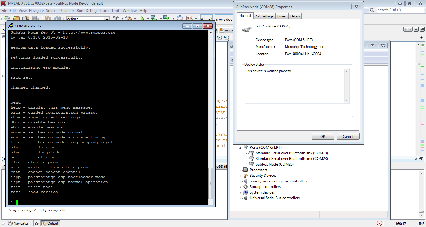
The firmware is now complete and has extra code to also passthrough (USB to UART) to the ESP for manual control and flash/bootloader operation. One final thing left to do is get the PIC flashing over USB. I will have this done in the next week or so.
![]()
Update 2:
The firmware is coming along nicely. USB CDC (serial) device is enumerating (and doesn't take up too much program space with the xc8 free compiler):
![]()
Update:
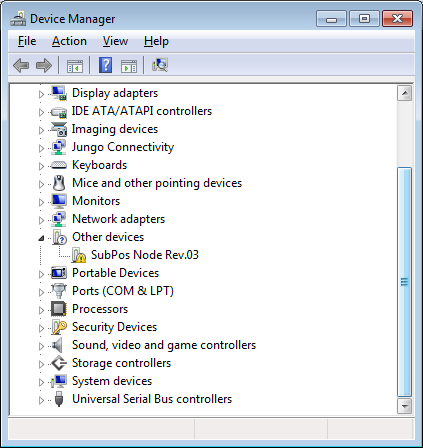
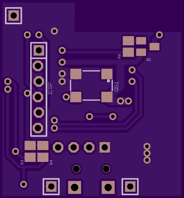
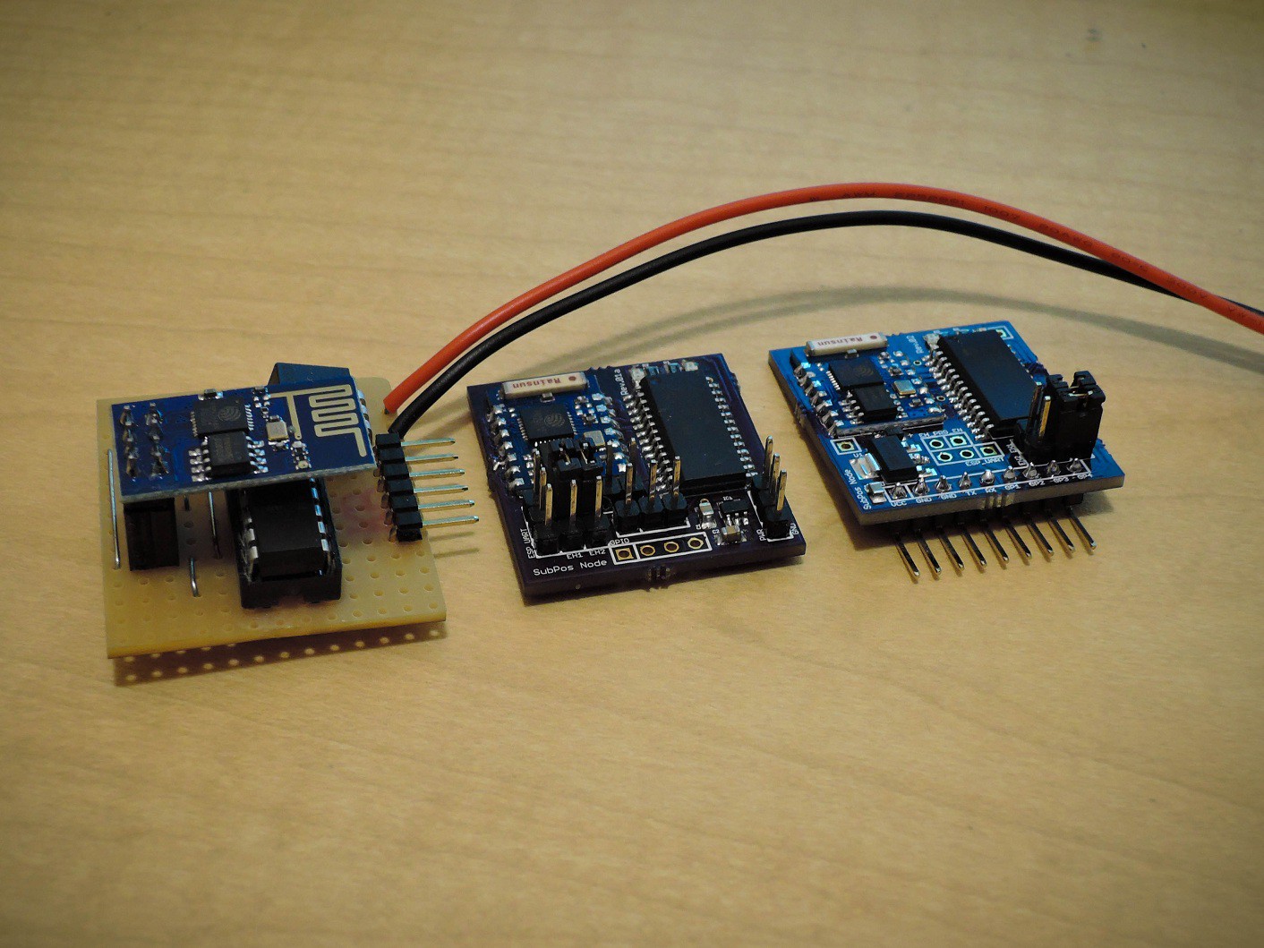
They have arrived and I am currently testing one of the assembled boards:
![]()
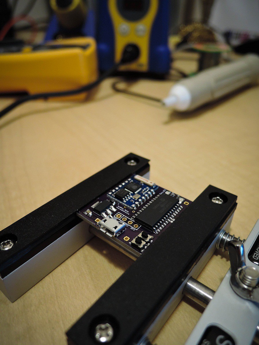
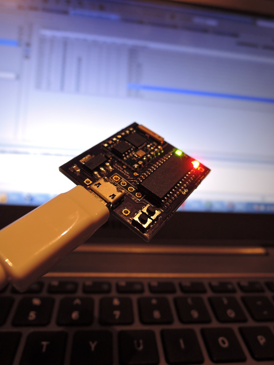
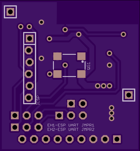
Working and sucessfully controlling ESP module power:
![]()
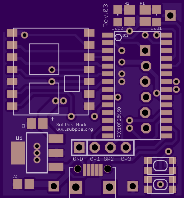
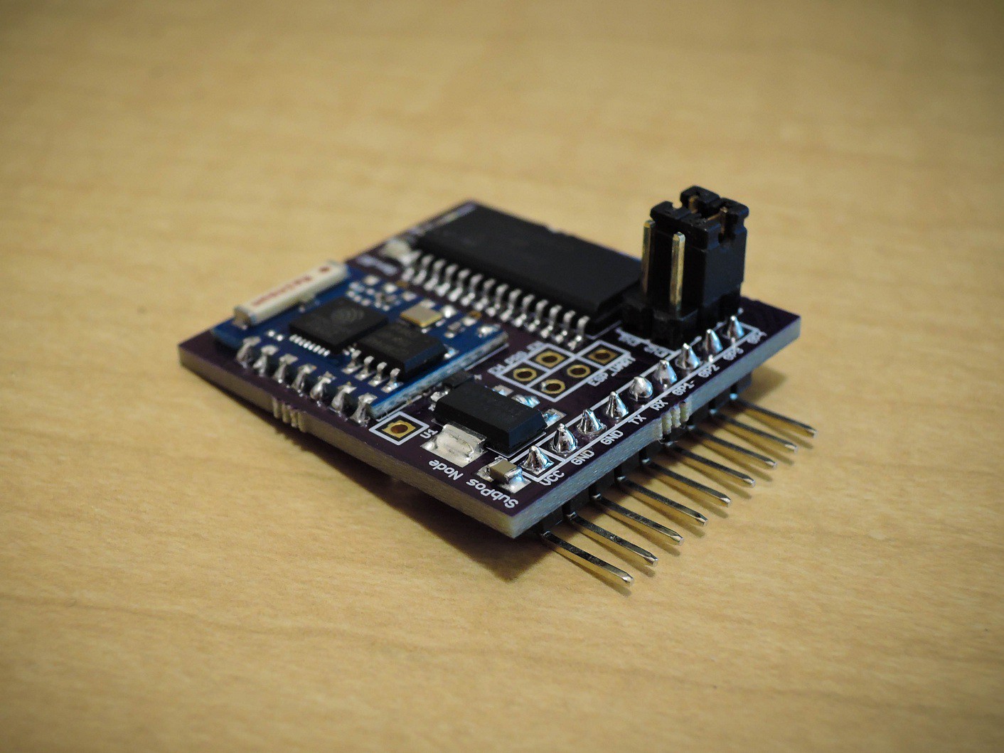
Just a quick update to say the revision 03 Nodes are out for production:
![]()
![]()
These will feature a USB based UART, USB power, MCU bootloader button (for flashing MCU), remote configuration button and ESP power control using a low Vce BJT transistor. Revision 04 is currently in development and will favour something other than the ESP module for tighter control over the beacon frames.
-
Hackaday Tests SubPos!
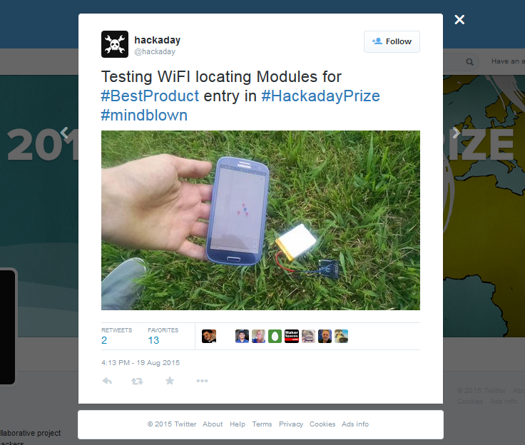
08/20/2015 at 07:15 • 0 commentsLooks like my shipment got there safely. The hackaday team has tested SubPos without any issues!
https://twitter.com/hackaday/status/634141199708909570?lang=en![]()
-
Videos!
08/17/2015 at 13:49 • 3 commentsQuarterfinals Video:
Semifinals Video:
-
How To Use the Node
08/15/2015 at 14:53 • 0 commentsWhether you are using the revision 01/02 or the newer (in development) revision 03 Node, they are all easily configured via a serial connection.
If you are using the 01/02 Nodes, you will need a UART(TTL) to USB converter to configure it via a serial console. With the 03 Nodes, plugging in the USB will both power it and provide a CDC based serial port which will install automatically in Linux or Windows 8.1/10 as a com port.
To power the Nodes, you will need at least a 3.3V supply @ > 300mA (the 01 node only goes from 3.3-5V whereas the 02/03 Nodes have an input rating of 3.3-20V with reverse battery protection).
You can use any serial console emulator you like with the following serial port configuration:
- Baud Rate – 9600
- Bits – 8
- Parity – None
- Stop Bits – 1
- Flow Control – None
Once connected, you should get the following on boot:
SubPos Node - http://www.subpos.org
fw ver 0.9.9 2015-07-23

eeprom data loaded successfully.

settings loaded successfully.

initialising esp module.

menu:
help - display this menu message.
wizz - guided configuration wizard.
show - show current settings.
hexd - enter pre coded hex data.
dbcn - disable beacons.
ebcn - enable beacons.
norm - set beacon mode normal.
acut - set beacon mode accurate timing.
freq - set beacon mode freq hopping (cyclic).
slat - set latitude.
slng - set longitude.
salt - set altitude.
clre - clear eeprom.
wree - write settings to eeprom.
chan - change beacon channel.
From here it is pretty simple to navigate, just type the command you want to run from the "help" menu and press enter. You can even correct mistakes before executing commands.
When you make changes to settings that need to be written to eeprom to remain persistant on reboot, an asterisk will show in the command area:
*>
To save, just type "wree" to save current settings to eeprom.
The red LED will illuminate when the device is performing critical operations like writing to eeprom. During boot it will stay illuminated until the ESP module initialises. If this stays illuminated for more than 10 seconds, there is an issue communicating with the ESP module. On the 03 firmware, this will automatically try to reinitialise the device, but on older versions, make sure the jumpers are set correctly.
If the red LED continues to stay illuminated on boot, the ESP module may need flashing.
-
Small Update, Rev 02 Boards
08/12/2015 at 06:04 • 0 commentsNot much going on this week while the videos are being made, they should be done by the end of the week. I have one of the Rev 02 Nodes made up and will repurpose some of the Rev 02 boards to test out the Rev 03 features. There won't be many of the Rev 02 boards as they are just a small change from Rev 01. The Rev 03 boards are shown here.
These boards use a Micrel MIC5209-3.3YS LDO, with voltage input up to 20V. They also have reverse battery protection.
![]()
![]()
![]()
Here is the look at the prototype, Rev 01a and Rev 02 boards:
![]()
-
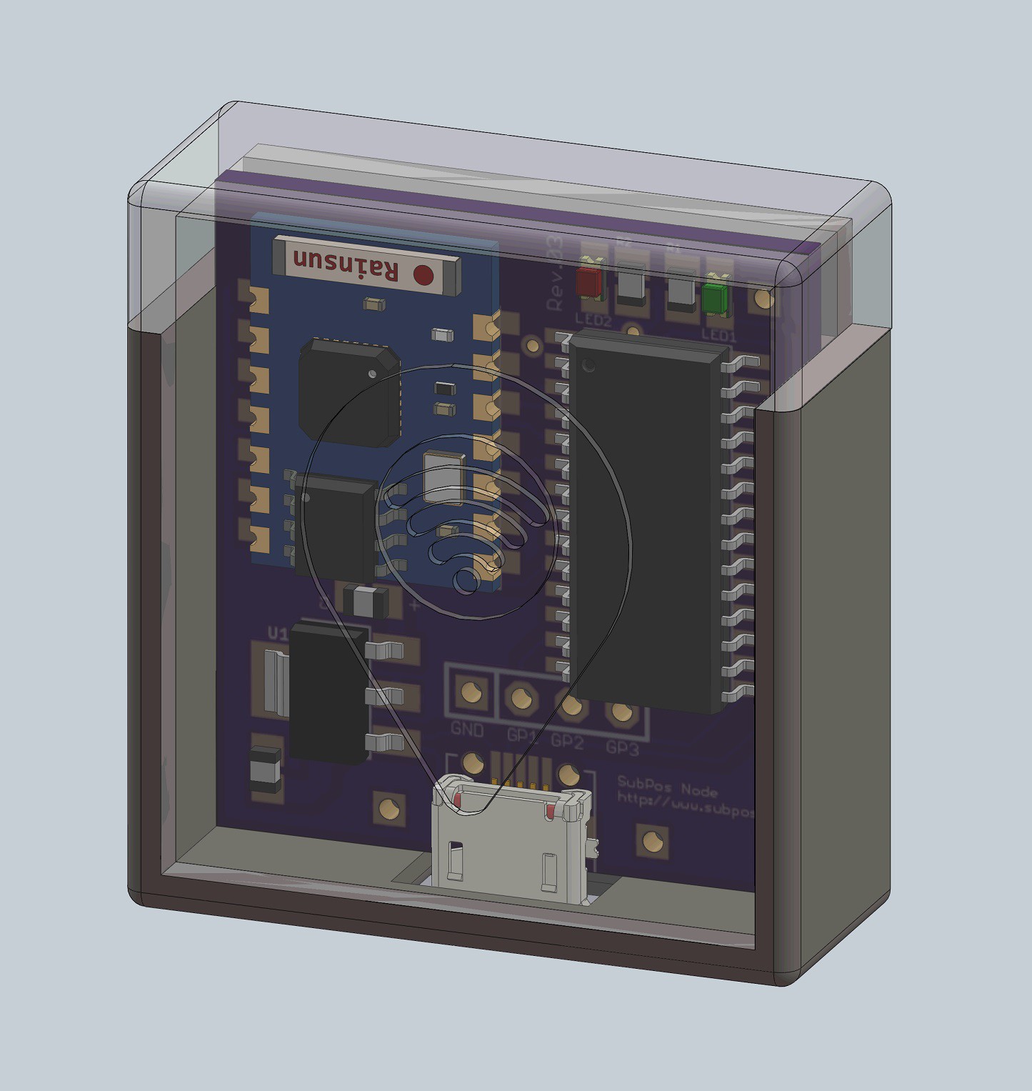
Introducing the SubPos Node
08/02/2015 at 10:30 • 0 commentsIn development is revision 3 of the SubPos Node. This version is a simplified variant of the development Nodes and would be close (feature wise) to the final product:
![]()
This version has a micro USB connector which is used to configure the device via a serial console as well as power it (it now uses a PIC18F25K50 to do this). In addition, the Nodes will allow for firmware flashing of both the ESP module and PIC over USB.
-
A Fine Result
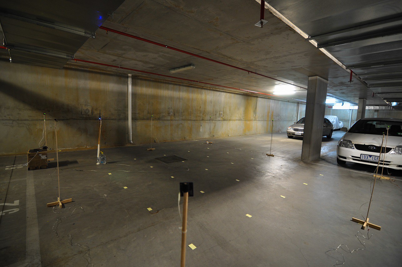
07/12/2015 at 14:35 • 1 commentI got another chance today to set up the nodes as shown in this project log. After some preliminary data analysis I can safely say everything is working as expected.
The nodes were setup up in a 6x6m array like so:
[1]------[2]------[3]
 |                 |
 |                 |
[8]               [4]
 |                 |
 |                 |
[7]------[6]------[5]
And samples were taken at 1 meter offsets:[1]------[2]------[3] | . . . . . | | . . . . . | [8] . . . . . [4] | . . . . . | | . . . . . | [7]------[6]------[5]
The first three nodes listed there are at the far end next to the wall in the image (the North side). Each of these points were measured with a laser distance measure.
I only got the chance to test the default mode without any special functions (frequency shifting etc.), but each Node was set to its own channel and the following average meter error plot was obtained:
![]()
Plot Data:
	1	2	3	4	5
1	 1.44m 	 1.35m 	 1.24m 	 1.51m 	 1.84m
2	 1.31m 	 0.93m 	 0.96m 	 0.95m 	 1.29m
3	 1.23m 	 0.51m 	 0.57m 	 0.72m 	 1.18m
4	 1.05m 	 0.84m 	 0.57m 	 1.16m 	 1.19m
5	 1.64m 	 1.18m 	 0.74m 	 1.24m 	 1.89m
Each of the data points corresponds to the sample points above (same orientation). The data for this plot was obtained by scanning the SubPos nodes at each sample point for 1 minute with a smartphone on a stand the same height as the Nodes (my Wi-Fi dongle on a stick had issues). This was then averaged and the error in meters was mapped out for each position (based on actual distance and the calculated path loss distance from RSSI). Every channel for each position was then averaged to create the plot above to show the average error at each point (in +- meters).
Note that this is not the trilateration algorithm, it's just raw distance error calculations for some quick visualisation (I will run the data through this later to test the true accuracy of it).
As you can see, the area maintains a distinct border close to the Nodes (which was expected), but as you move towards the center, the accuracy increases substantially (more than accurate enough to find your way in a shopping mall or underground carpark). In a much larger area with many Nodes this error will average out and err on the smaller side.
My next test will involve frequency switching (which I expect will smooth out the average), and then I will look to test in a much larger environment when a suitable location is found.
But for the moment, I am very very happy with the baseline results of the default Node mode.
-
Not as Promised
07/09/2015 at 12:40 • 0 commentsI was going to have a really nice video with lots of data and deliciousness, but with my unsucessful test run last week this will be on hold a little longer.
In the meantime I have made a quick video that shows the Node firmware and serial user interface in action. No audio, just annotations and running at normal speed:
-
No This Fun 2
07/01/2015 at 14:44 • 0 commentsNothing is ever easy. I spent about 3 hours setting all of this up (not to mention the several hours of prep work to get it all ready) to test 8 nodes in a square formation with test points at 1m intervals:
![]()
It turns out there are a few issues:
- The length of the cables don't allow some of the Nodes to pull enough current (the voltage is fine), causing them to reset constantly.
- Since the Nodes are connected to a common power supply (I used 2 batteries, one for each side), they all turn on at the same time and effectively start transmitting their beacons at the same time, causing a bunch of collisions (this isn't so much of a problem with frequency shifting, but I will add in some startup randomness).
- Changing the channel on startup doesn't work straight away, so it starts with the default channel. I need a longer delay.
- I was relying on the status LEDs to make sure they were programmed correctly. The status LEDs indicate issues with the ESP module and the like. Some of these Nodes appeared to be working, when they in fact weren't (more thorough testing required for each Node).
- Each Node has the same MAC address by default, I will need to change the firmware to adjust the MAC address based on position parameters and ID. This isn't a major issue, except that some SSID viewing software sorts/replaces based on MAC address (this doesn't affect the Android API).
So back to development... At least I got a neat animated gif:
![]()
SubPos Positioning System
A "dataless" Wi-Fi positioning system that can be used anywhere GPS can't.