Ulf Winberg
-
Custom PCBs
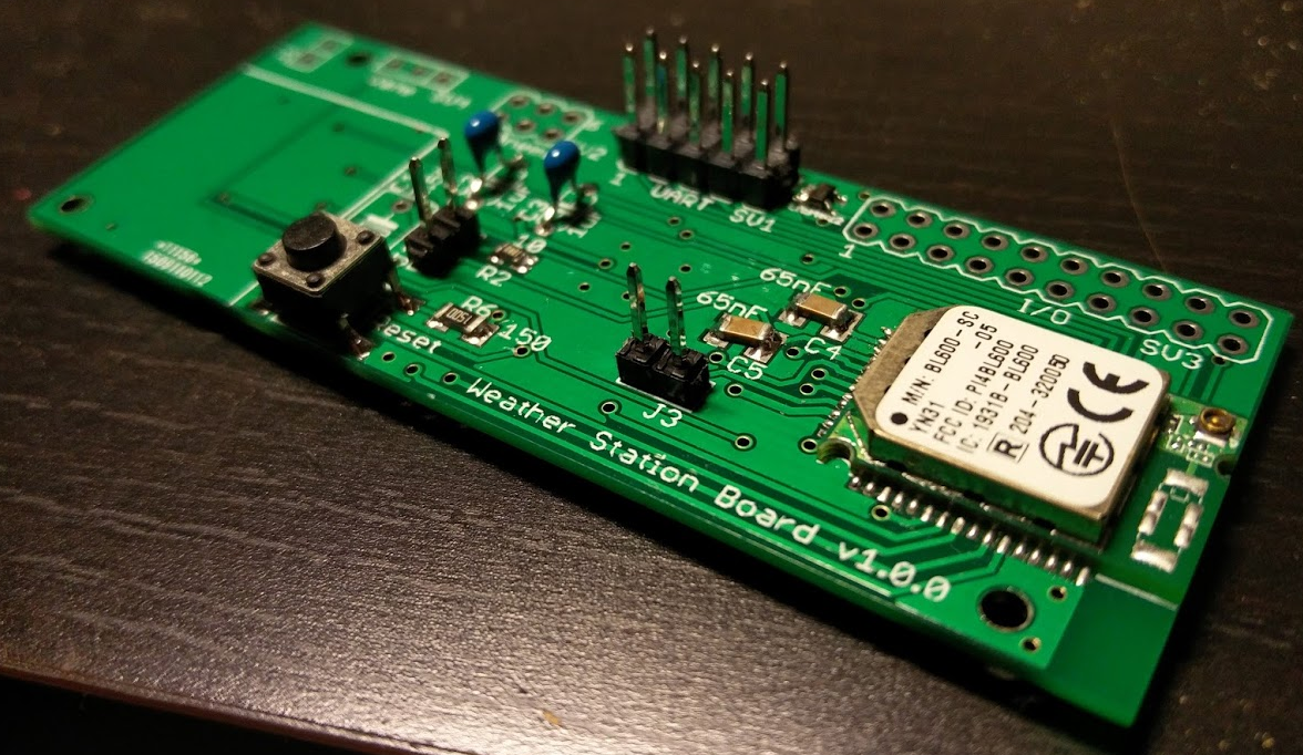
03/19/2017 at 12:05 • 0 commentsPreviously I had not received my custom PCBs and had to do with experimental boards. Now I have the boards, did some mandatory error fixes, and finally got it working!
![]()
I found a few issues in the design on the way:
- I should have chosen through hole for the button, since they are more readily available and a lot cheaper. I simply bent the legs to solve it for now.
![]()
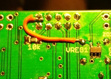
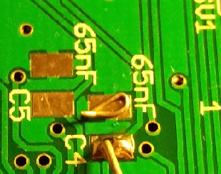
- VDD was by mistake not connected to the Communication Board header (I need it for the level shifter of the UART signals). Fixed with a small wire.
![]()
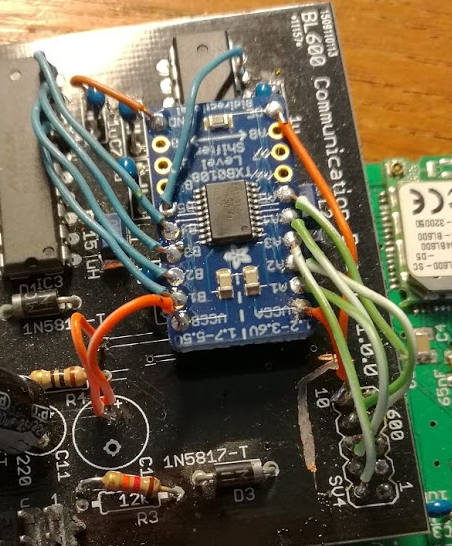
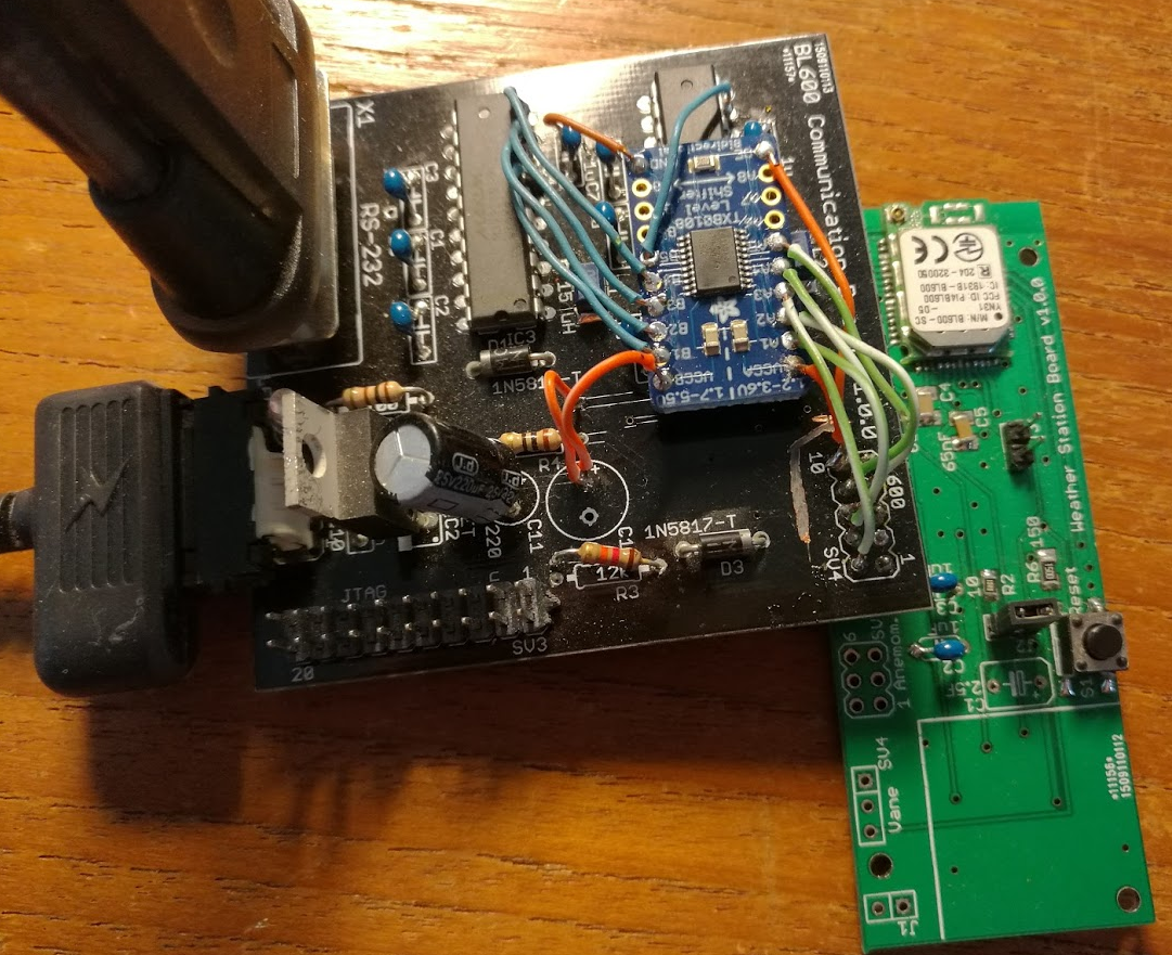
- Communication Board failed, since the Weather Station Board regulator was not powerful enough to power the MAX3218 chips. I ended up cutting some traces and adding an Adafruit level shifter in between.
![]()
- I should have used a micro USB connector for the 5 volts on the Communication Board, instead of pin header (what was I thinking?)
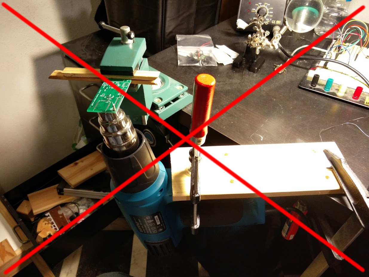
All the parts were solderable with a regular soldering iron, except the BL600 Bluetooth transceiver. My first attempt was to use a heat gun from below. Didn't work very well... I placed some solder to see when it melted (see picture below), but even on the highest temperature of the gun, it didn't happen.
![]()
![]()
Instead I borrowed a hot plate from work, and when it reached the set temperature I carefully slid the PCB with the BL600 and some solder paste onto the plate, and as soon as everything seemed to have melted (a few seconds only) I slid it away again (no picture on this I'm afraid).
So far I've only tested the UART communication and the reset button, but that works reliably. Note that there still might be errors on the Weather Station Board, since I have not tried out all the sensor circuitry yet.
So, here are the boards connected, and working:
![]()
My next step is to try out bluepy on the client side, as an alternative to the messy gatttool/pexpect combination I'm currently using.
- I should have chosen through hole for the button, since they are more readily available and a lot cheaper. I simply bent the legs to solve it for now.
-
Price - Pretty close!
09/27/2015 at 16:43 • 0 commentsThe whole idea of this project was to make it cheap, so that most people would afford it. I have now purchased all the parts for the second prototype, and have an initial figure:
$ 54.7 or € 48.8
See the BOM for the complete list and calculations.
Some notes:
- The prices are excluding taxes.
- All prices are taken from Digikey, a few days before posting this.
- This is a prototype, and there is room for optimization in terms of price. As an example, the push button currently costs over $2 because I chose a surface mounted version. I can get it for one tenth of that if I allow through hole.
- The solar panel is probably over-sized in comparison to the power consumption I have in mind. It is about $12, and I think a much cheaper one can be used. Time will tell!
- I'm so far assuming that you or a friend has a 3D printer (latter in my case), and I have not included the price of material and electricity for printing.
- I'm also assuming that you have a computer fan laying around, to be used for the anemometer. Quite a stretch, I know. I'm still not convinced that getting energy from the wind will work out. If it doesn't, I might combine the wind vane PCB with anemometer, which would save a lot of money (not only the fan, but also circuitry on the main PCB). In any case you can buy a small fan for € 6 at digikey, if really needed.
If I would have stated € instead of $ in the begging it would look better, but all in all, I'm very happy with this initial figure. It proves that my initial statement was not too far off.
-
Semifinal Video
09/17/2015 at 21:12 • 0 commentsThe video for the semifinal is up!
-
First Prototype - Putting the Parts Together
09/16/2015 at 21:04 • 1 commentThe time has come to put electrical and mechanical (and some emotional) parts together! A friend of mine that made his own 3D printer helped me with the mechanical parts (thanks once again Martijn Sanderse!).
![]()
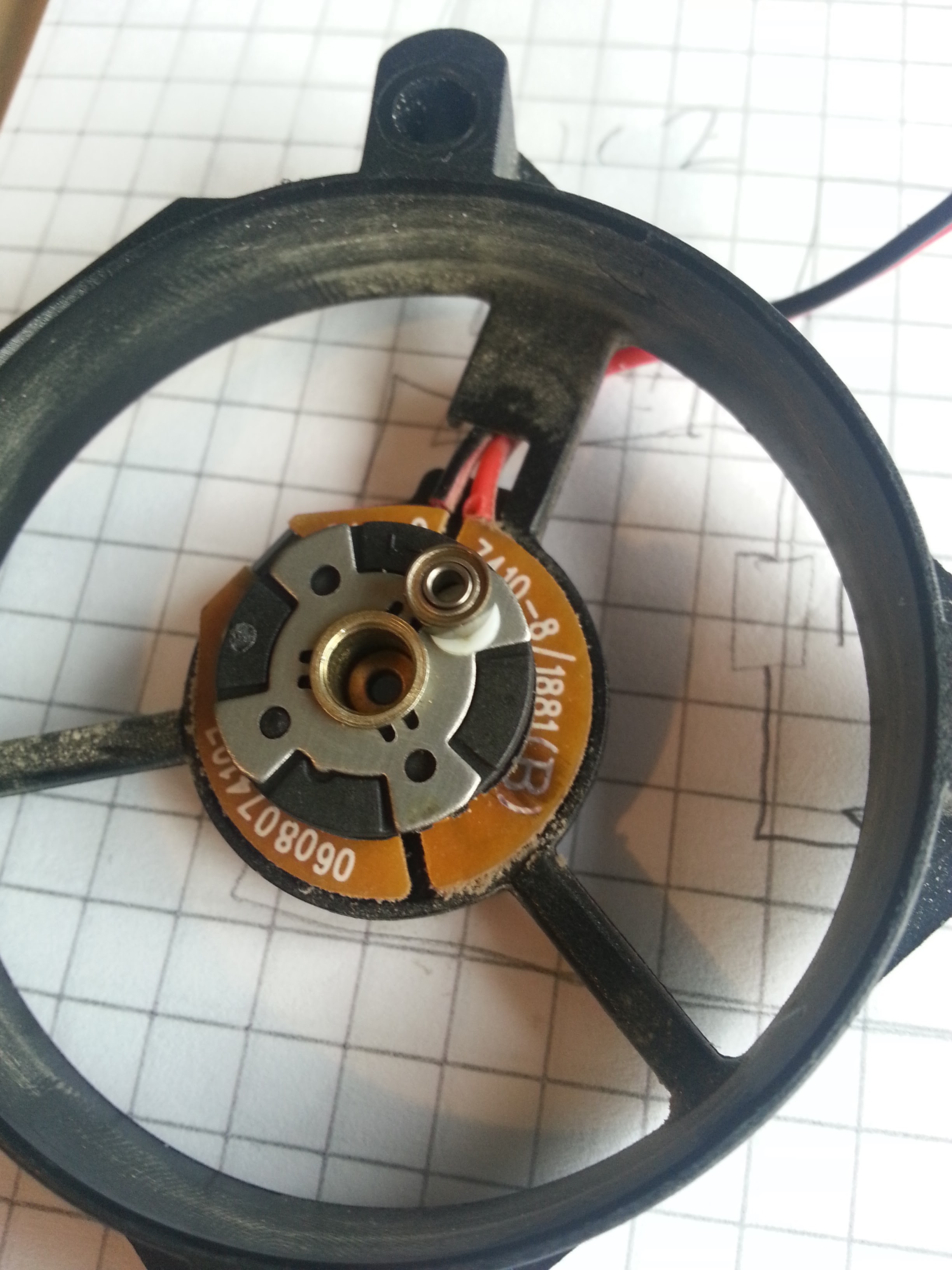
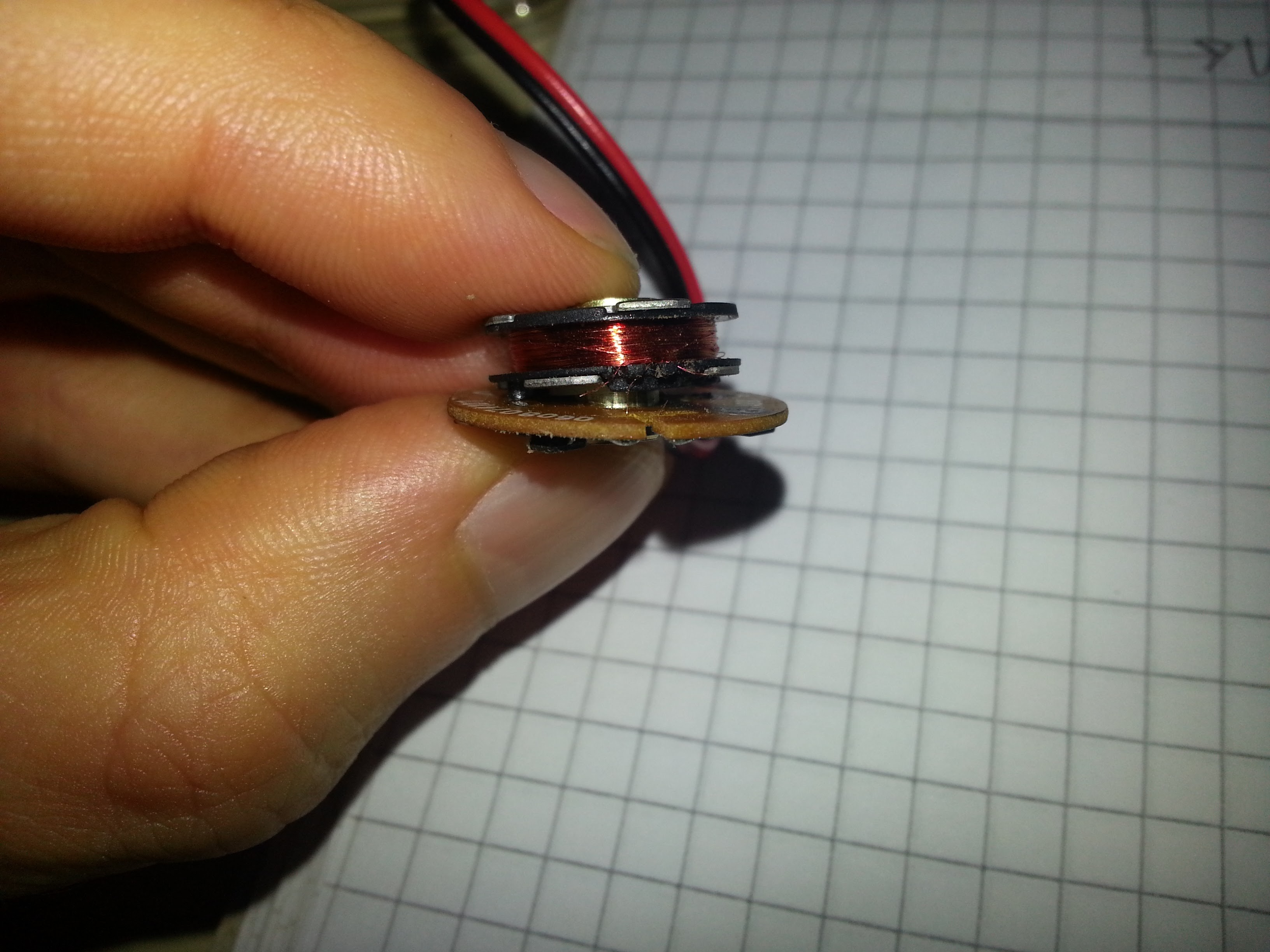
As a first step however, I needed to extract the parts I needed for the anemometer. I'm using a small DC computer fan for this purpose.
![]()
As seen above, I managed to get it open, but in the process I ripped the tiny coil wires (DOH! see picture below). For the first prototype, I will only use the hall sensor, in other words.... (ie, not using any wind energy)
![]()
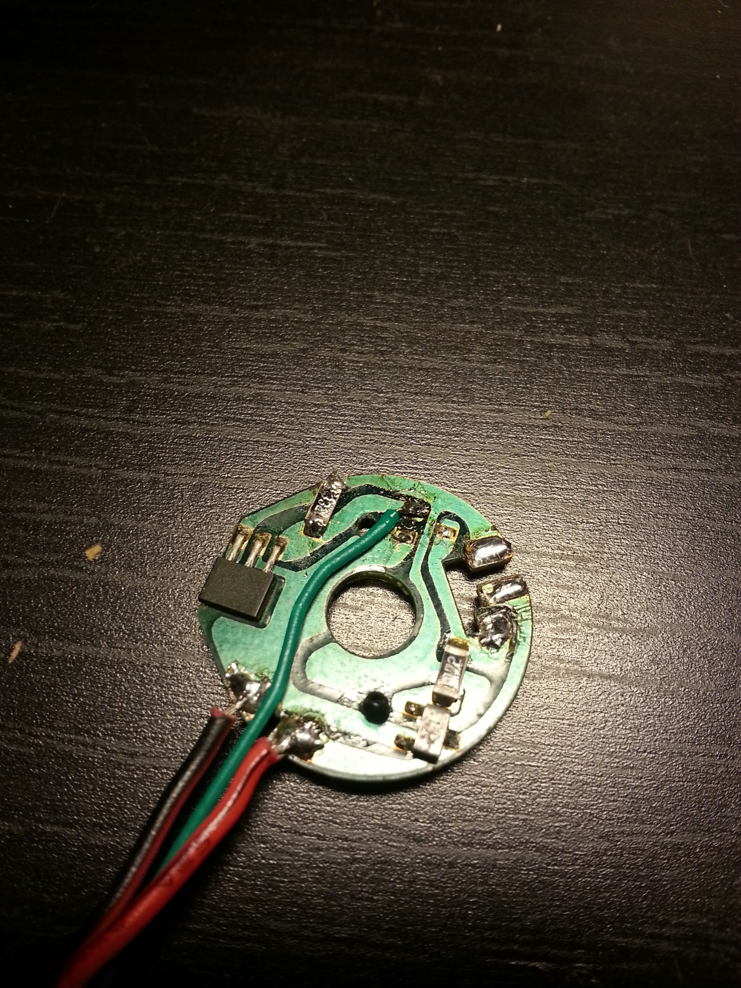
The hall sensor is the largest IC in the picture below. In fact, I had another, slightly larger fan in mind to start with, but it turned out that the hall sensor on that fan needed amplifier and hysteresis circuitry. This one only needs VCC and a pull-up resistor on the output. In the picture you can see that I have added a wire for the output and removed one component (I believe is was a diode).
![]()
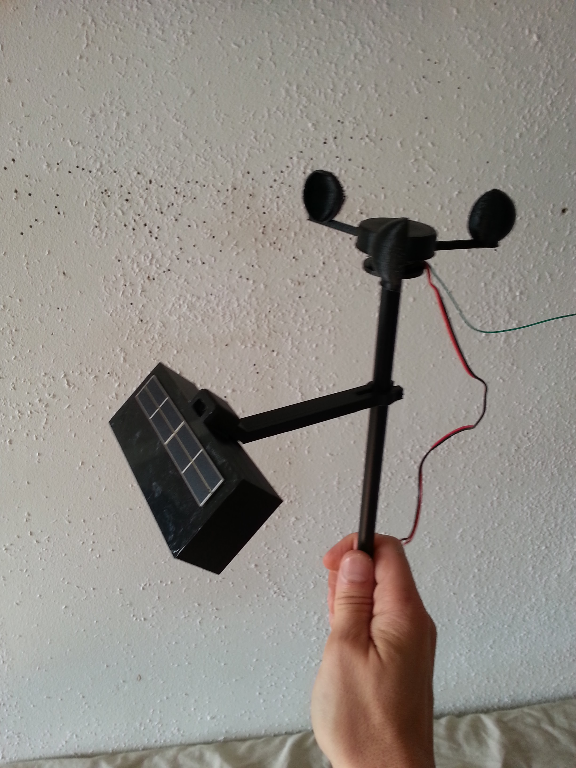
Next, the fan parts need to be fitted on the 3D printed structures. I cut the wings on the part in the bottom left, and attached it inside the anemometer. The bottom right part, with the wires, I glued on the holder seen on the top right (on the side which is down in the picture).
![]()
And here we have all the parts together, including the solar panel!
![]()
Stay tuned! In the next post I will publish a short video, showing the prototype in action.
-
Mechanical Parts
09/16/2015 at 20:34 • 0 comments![]()
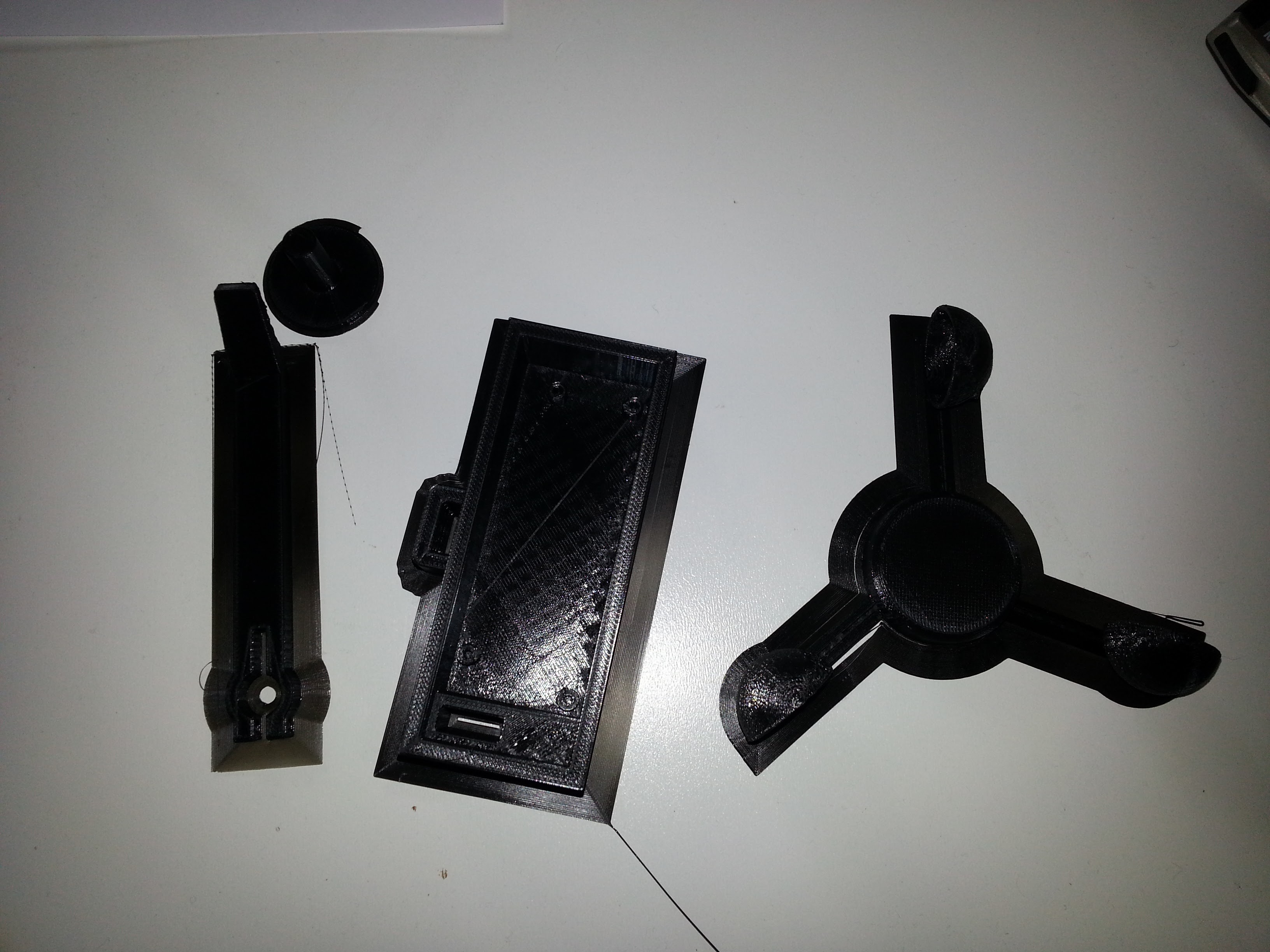
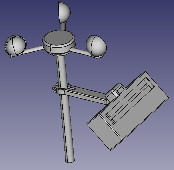
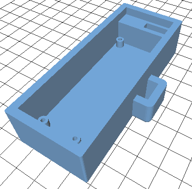
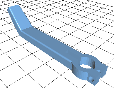
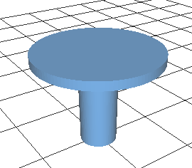
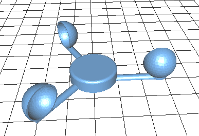
A weather station is worth nothing without proper mechanical parts... Therefore, I decided to learn how to use FreeCAD. For this first prototype I ended up with four separate parts:
- Main enclosure (contains the main PCB and solar cell)
- Arm for connection to middle rod
- Connection piece between middle rod and computer fan part
- Anemometer for wind speed detection and energy
For the middle rod, I intend to use a metal pipe from an old IKEA bed I had laying arond. That could be printed as well or bought somewhere (the outer diameter is 10 mm and inner about 9 mm).
I took special care to make the parts printable (see future post on how successful I was).
1:
![]()
2:
![]()
3:
![]()
4:
![]()
-
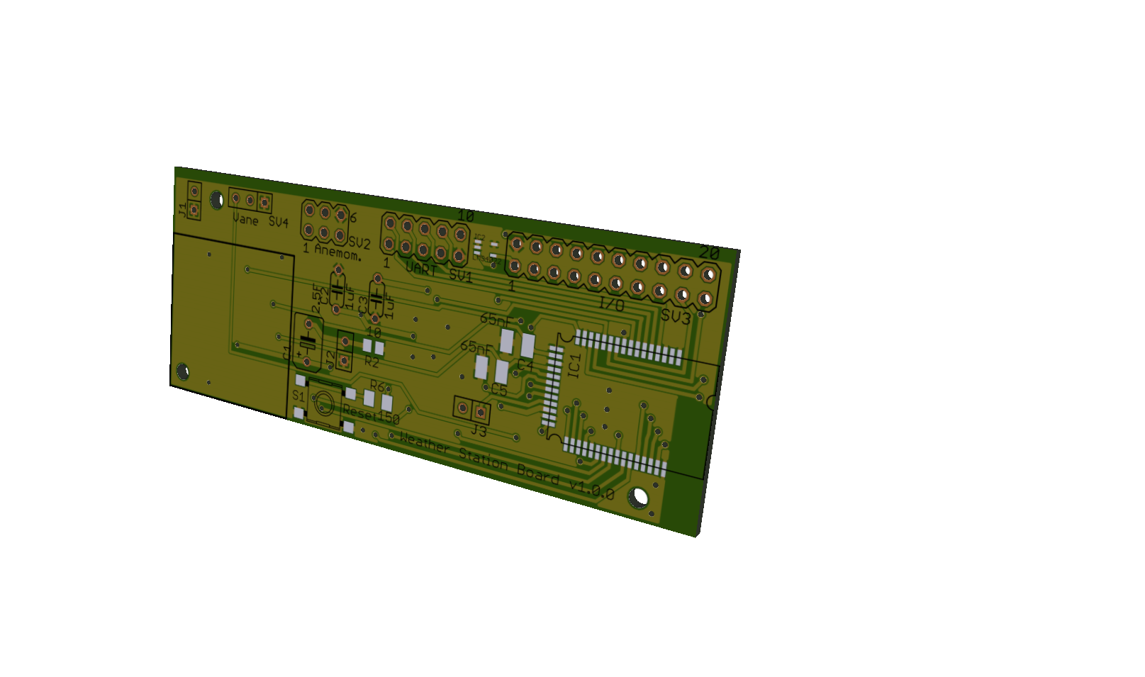
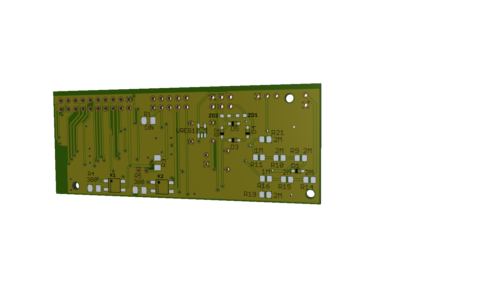
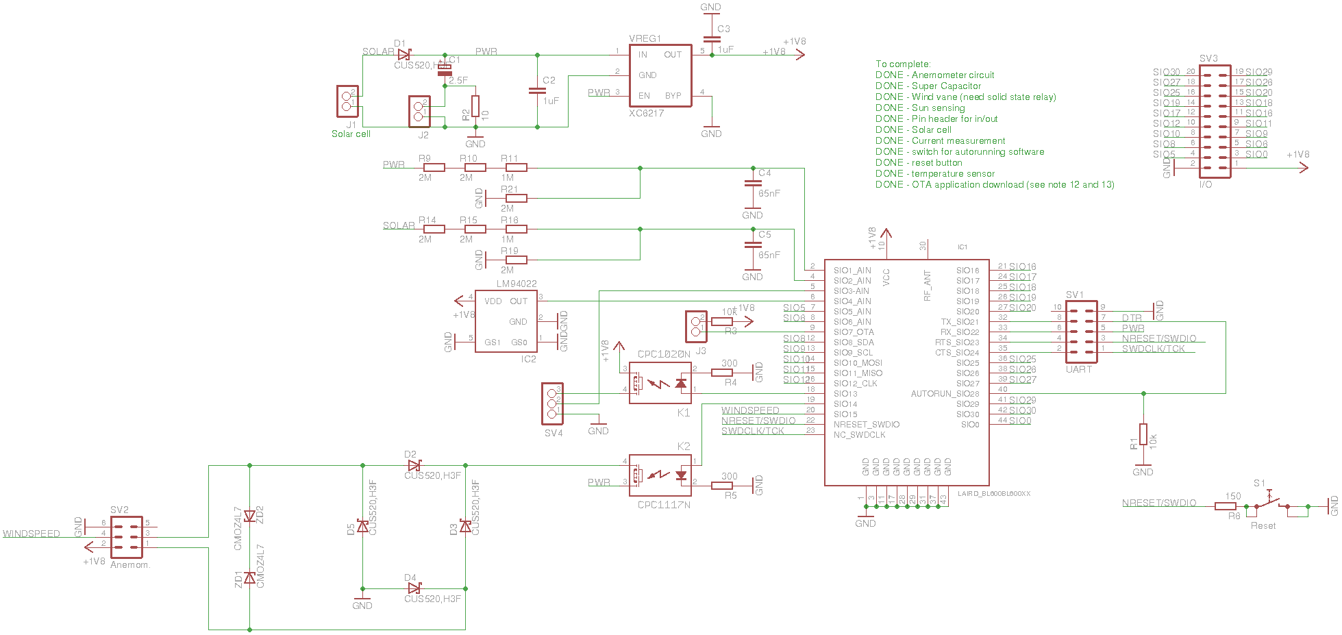
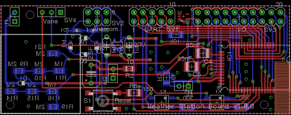
Weather Station Main PCB
09/16/2015 at 20:05 • 0 commentsFinally I was able to complete the design of the main PCB I want to use! It is not complex, but since I wanted to make it small and make sure all unused IOs were available for additional external sensors, the routing took some effort.
There are four header pin connectors, with the following functions, starting from the left in the first picture:
- Solar cell (sun sensing and charging)
- Wind vane (wind direction sensing)
- UART (connection to external PCB for UART, JTAG and external power, see older post)
- I/O (Analog and digital lines not already used, to allow add-on sensors)
There is a large area to the left, which is reserved for the super capacitor, and next to it is a reset button (useful if bluetooth connection needs to be reset). I also added a header pin close by to allow current measurement. That will be handy when the current consumptions is to be optimized. The last header pin (J3) is to allow over-the-air update of the software. Can be extremely useful if the weather station is already placed outside.
As always you can find the source files from the git repository link.
(3D pictures below made using online tool at http://mayhewlabs.com/3dpcb)
![]()
![]()
![]()
![]()
-
Project Video
08/16/2015 at 17:44 • 0 commentsI just uploaded a video about the project. Feel free to have a look!
-
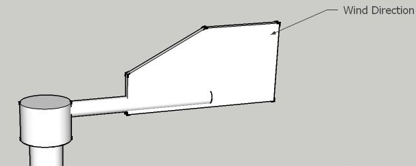
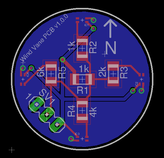
Wind Vane PCB
08/11/2015 at 17:19 • 0 comments![]()
To measure the wind direction I need a wind vane. A simple way to do that is to use hall sensors and a small magnet, which rotates with respect to the sensors (the hall sensor triggers an output when the magnet is close). My solution is to use four such sensors, one for each cardinal direction (north, south, west, east).
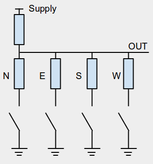
Note that this does not mean I'm restricted to measuring only four directions; by placing the magnet at the correct distance, I will get two sensor readouts when it's in between directions. In other words I get eight directions (see table).
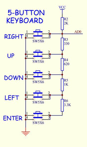
Direction Readout (N,W,S,E) North 1,0,0,0 North-East 1,1,0,0 East 0,1,0,0 South-East 0,1,1,0 South 0,0,1,0 South-West 0,0,1,1 West 0,0,0,1 Noth-West 1,0,0,1 The most straight forward way to connect this to the BL600 processor is to use in total six wires; four to BL600 inputs and two for GND and supply. That's a bit of waste of inputs that can be used for other peripheral devices, and I need the vane to be quite far from the main PCB so I'd also like to reduce the amount of wires. Therefore I decided to combine the four digital signals into one analog.
It's quite common to combine several buttons into one analog signal (see example here). The problem, though is that they most of them assume that you're only going to press one button at a time. For example, in the picture below, if I press "RIGHT", it doesn't matter what other button is pressed, since "AD0" is already grounded.
Instead I used this approach:![]()
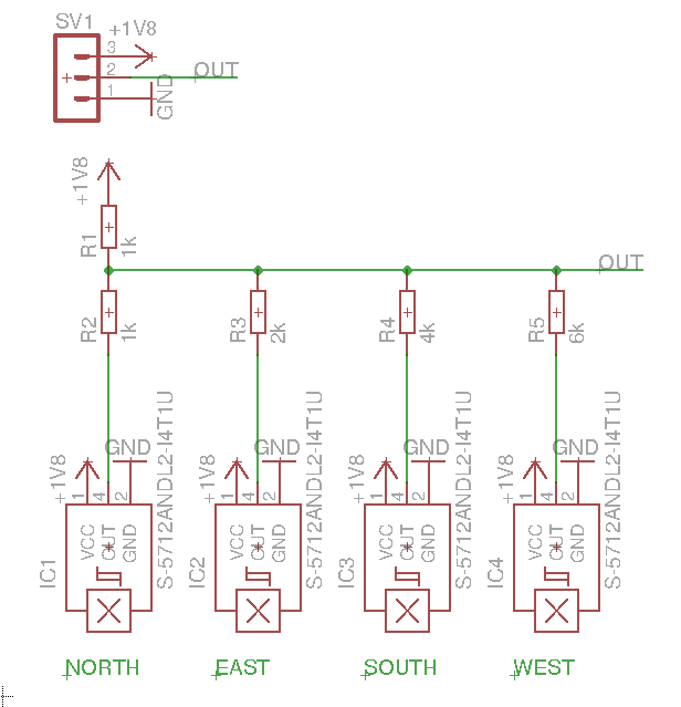
By choosing different values of the resistors N, E, S and W, I will get different voltage outputs for combinations of presses. I made a spreadsheet to fiddle with resistor values (see here) and after a while I found a configuration with maximum 70 mV difference between the states I care about. The worst case ADC resolution is about one tenth of that, so that should be fine.![]()
Considering that I need quite accurate placement of the sensors, I decided to make a PCB. Below you can see the schematic and layout.
![]()
![]()
As usual, all the source files can be found through the project links.
-
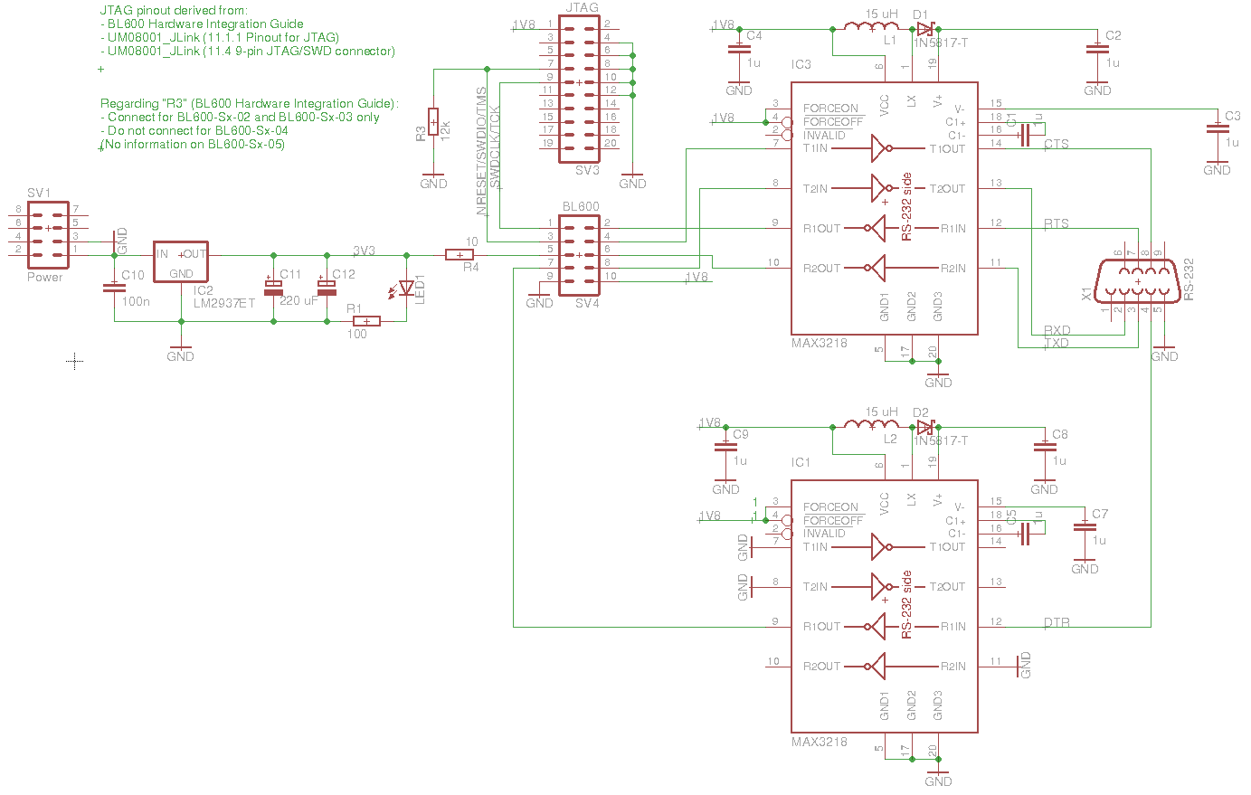
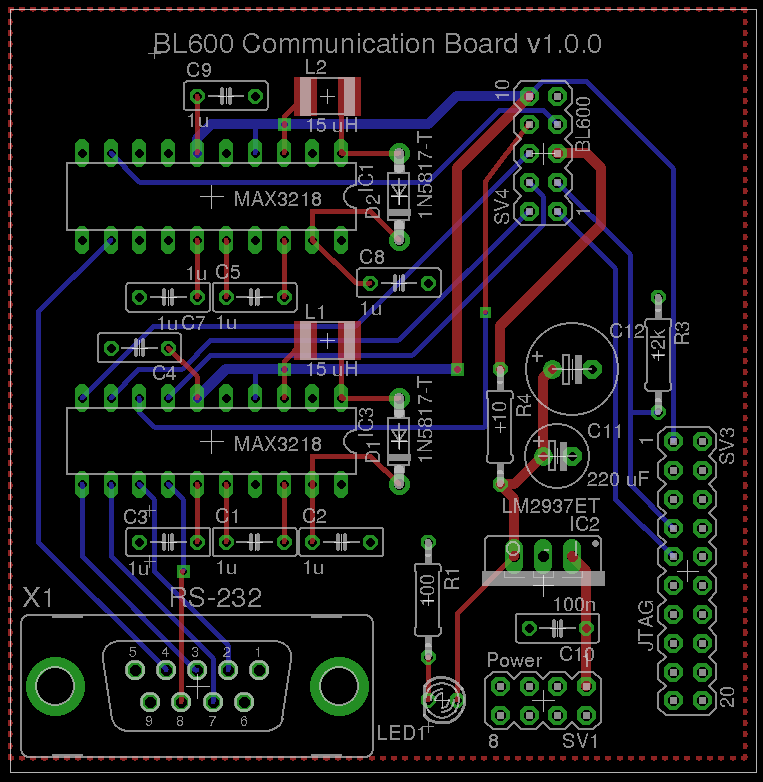
BL600 Communication Board
07/09/2015 at 21:06 • 0 commentsI will need to design a PCB for the weather station, where I will place the BL600 and the super capacitor, amongst other things, but I will also need something to communicate to the BL600. Since the weather station should be small and as cheap as possible, I want to push the RS-232 to UART conversion, power supply and JTAG circuitry out from the main board. Therefore, I've designed a separate board for that (see pictures below).
![]()
![]()
The source files can be found here. Next post will be about the design of the main board.
-
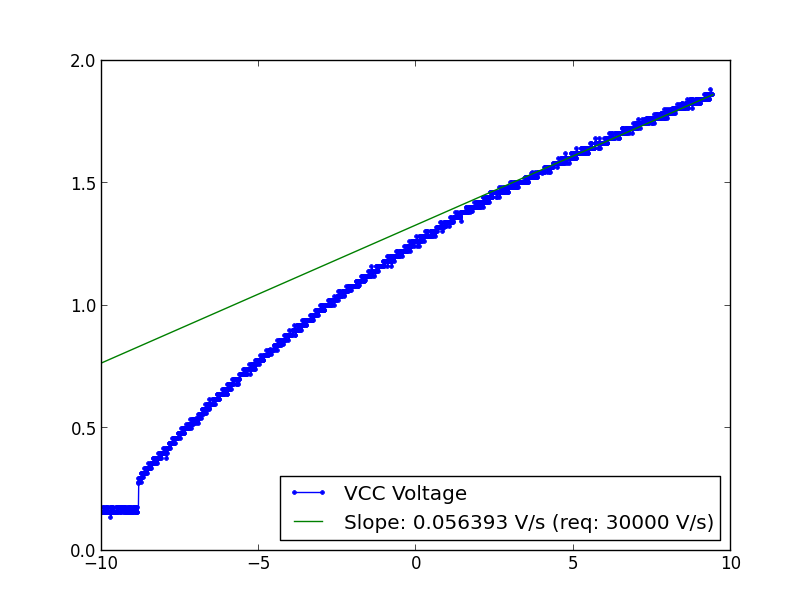
Slow VCC Rise Time
06/10/2015 at 11:48 • 0 commentsWhen the weather station is powered by the sun and wind, the increase of VCC will be quite slow, while the capacitor is charged. This might cause the microprocessor to not start up properly, so I decided to test it.
There is reset circuitry built in to the BL600 to take care of such problems, but looking at the data sheet, it is not enough. A minimum rise time of 60 ms from 0 to 1.8 V is mentioned. Anyway I set out to test how bad it actually is by charging and discharging the capacitor 10 times, while observing if connection is made with my host computer. I have made a script to continuously try to make a connection, and I uploaded smartBASIC code I new worked well.
To my surprise, it worked every time (see below):
Started gatttool
2015-05-25 14:45:06.887746 Trying to connect (try nr 6)
Successfully Connected to Bluetooth Device
2015-05-25 14:46:18.124806 Battery level: 8 % (measurement nr 2)1)
2015-05-25 14:48:18.699739 Trying to connect (try nr 1)
Successfully Connected to Bluetooth Device
2015-05-25 14:49:35.850811 Battery level: 9 % (measurement nr 2)1)
2015-05-25 14:53:36.967842 Trying to connect (try nr 4)
Successfully Connected to Bluetooth Device
2015-05-25 14:56:09.792776 Battery level: 4 % (measurement nr 3)))
2015-05-25 15:01:31.447688 Trying to connect (try nr 6)
Successfully Connected to Bluetooth Device
2015-05-25 15:02:38.616737 Battery level: 10 % (measurement nr 2))
2015-05-25 15:11:21.447861 Trying to connect (try nr 11)
Successfully Connected to Bluetooth Device
2015-05-25 15:12:49.687791 Battery level: 10 % (measurement nr 2))
2015-05-25 15:16:10.567832 Trying to connect (try nr 3)
Successfully Connected to Bluetooth Device
2015-05-25 15:18:18.354815 Battery level: 4 % (measurement nr 3)))
2015-05-25 15:37:44.169875 Trying to connect (try nr 27)
Successfully Connected to Bluetooth Device
2015-05-25 15:38:44.932914 Battery level: 11 % (measurement nr 2))
2015-05-25 15:42:05.927878 Trying to connect (try nr 3)
Successfully Connected to Bluetooth Device
2015-05-25 15:43:39.133719 Battery level: 10 % (measurement nr 2))
2015-05-25 15:46:19.847809 Trying to connect (try nr 2)
Successfully Connected to Bluetooth Device
2015-05-25 15:47:23.089177 Battery level: 10 % (measurement nr 2)
2015-05-25 15:49:23.659031 Trying to connect (try nr 1)
Successfully Connected to Bluetooth Device
2015-05-25 15:50:32.526885 Battery level: 11 % (measurement nr 2))
2015-05-25 16:40:08.167808 Trying to connect (try nr 72)
The rise time I used was much slower than the requirement mentioned in the data sheet, as seen in the picture below:
In other words, I will continue with the PCB design relying on the reset circuitry of the BL600. At least for the first prototype that should be good enough.
Low Cost Weather Station
Wireless weather station, powered by the sun and wind it intends to measure, below $50.