Alex
Alex-
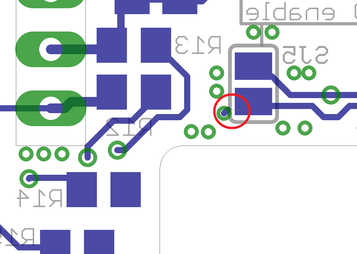
Error on the rev2 PCB!
07/25/2015 at 20:50 • 0 commentssadly I made an mistake while designing the PCBs. There is a missing wire:
![]() But this does only affect the RX, TX and Power LED so if you are not using any of these LEDs you do not have to worry. The PCBs do work without any modification. If you need the LEDs get a screwdriver and a soldering iron and fix it like this:
But this does only affect the RX, TX and Power LED so if you are not using any of these LEDs you do not have to worry. The PCBs do work without any modification. If you need the LEDs get a screwdriver and a soldering iron and fix it like this:![]()
So I did fix it on both boards I soldered so far. It is not difficult. Tomorrow I will post pictures of the finished board in their nice acrylic cases. They do look good.
-
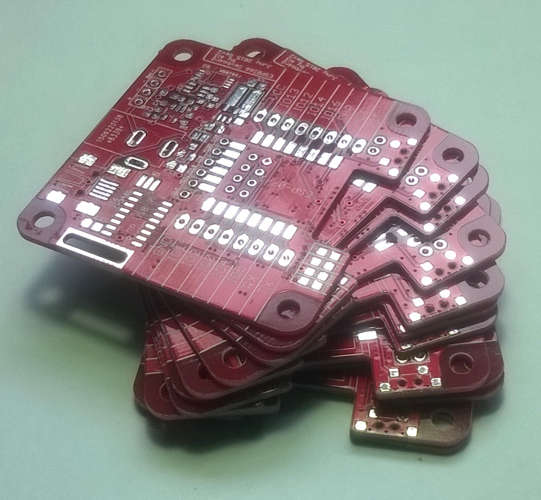
New PCBs arrived
07/23/2015 at 12:12 • 0 commentsThis was in the post today:
![]()
Some nice board for ditypcbs.com. Now it is time for some soldering. Sorry for the bad image, but this was taken with my phone.
-
Paper test for Rev2
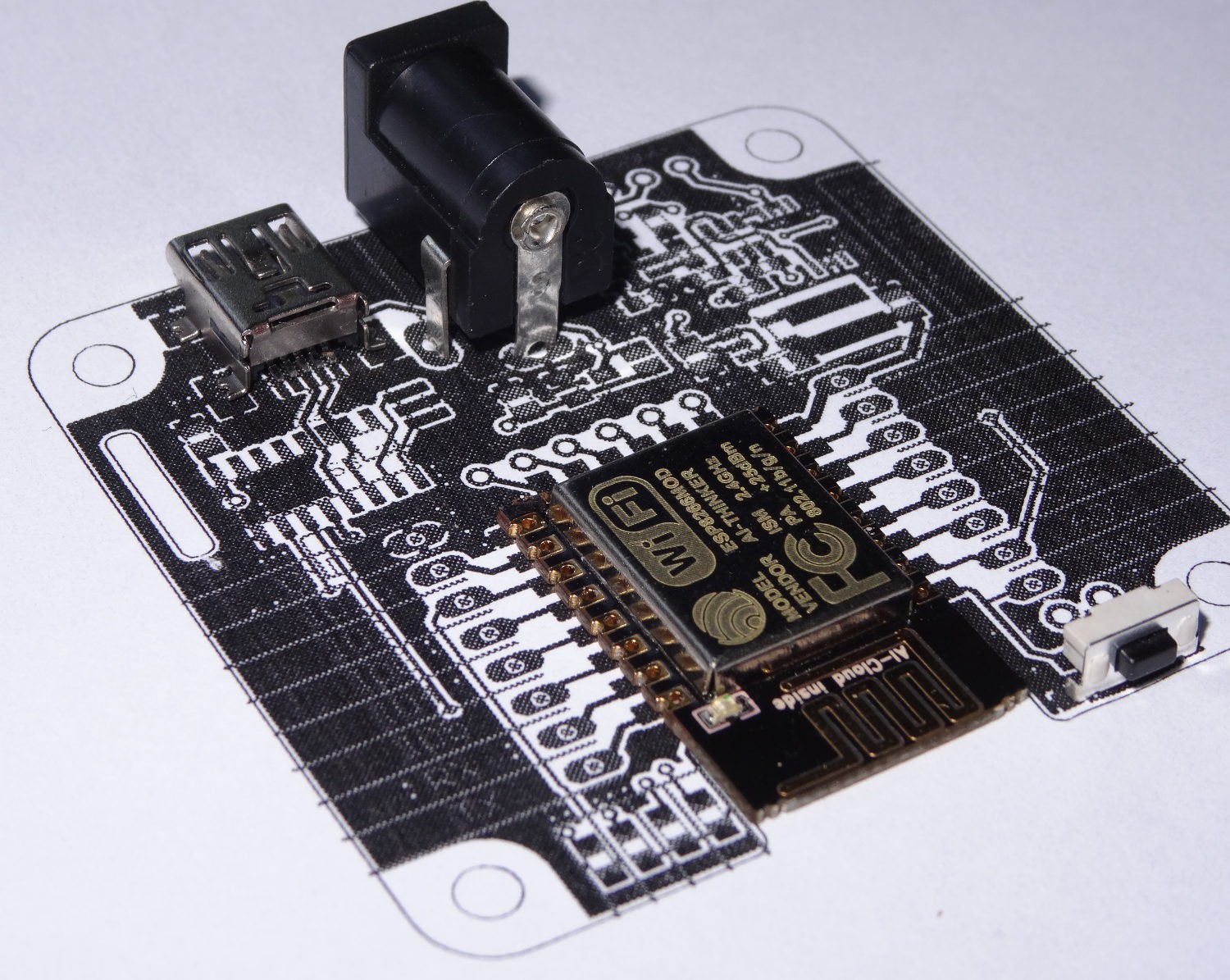
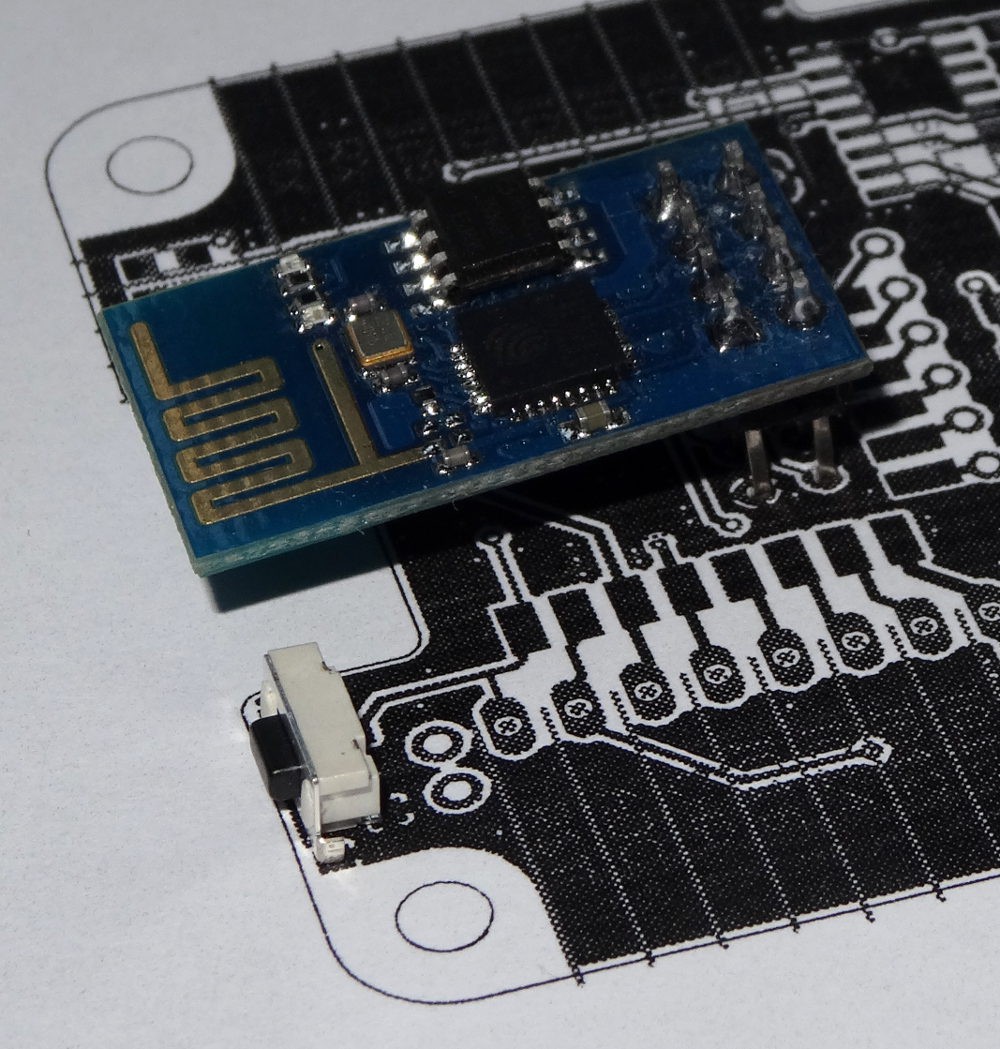
07/11/2015 at 16:42 • 0 commentsI am still waiting for the new PCBs. but most components did arrived. Including the ESP-12E Module. So I made a small paper-PCB test. And it looks good.
![]()
Also the possibility to use Rev2 with the ESP-01 module looks good:
![]()
On both Images you can also see the new reset switch. It is accessible from the side. So that laser cut acrylic sheets can be used as case. Therefore see also also last log.
-
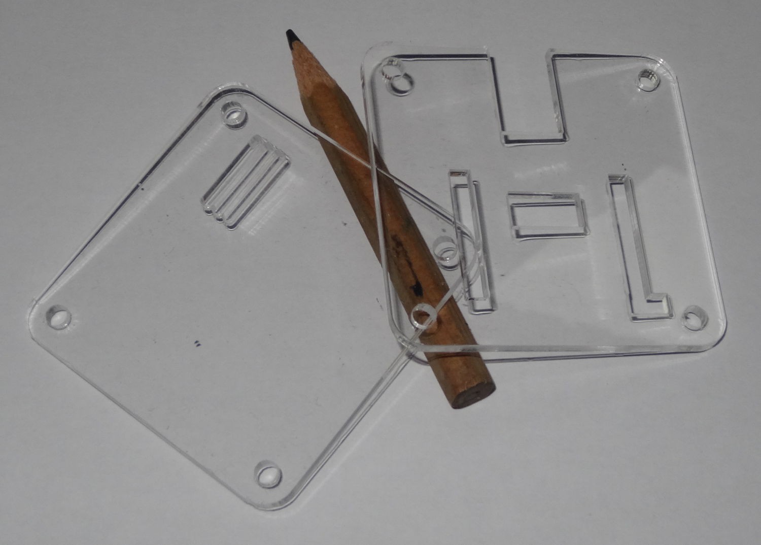
Acrylic sheets for Rev2 case
06/23/2015 at 16:51 • 0 commentsToday the acrylic sheets for the case of Rev2 arrived. Sadly I have to wait for the PCBs to asamble the first Rev2.
![]()
This case is based on this.
-
Rev2 PCBs ordered!
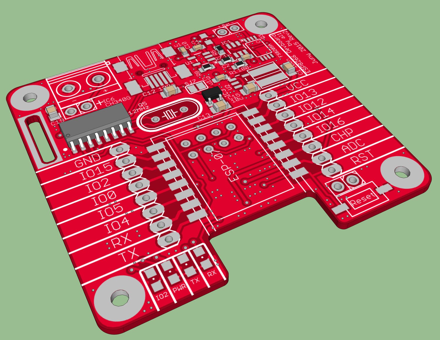
06/20/2015 at 20:28 • 0 commentsJust a quik update: I orderd rev2 boards. This time they will be red and I will test 1.2 mm thickness instead of 1.6 mm.
-
Layouting Rev2 Part 4
06/16/2015 at 17:49 • 0 commentsThis is hopefully the last log about layouting rev2.
I did add support for ES-P12E. Therefore I had to go back to the small SMD resonator I used in rev1. I also changed some minor issues, including the wring labelling of IO 4 and 5 (the names a also wrong on my modules).
![]()
-
Layouting Rev2 Part 3
06/07/2015 at 21:20 • 0 commentsI was thinking a little bit about an enclosure for my boards. First I wanted to use this on: http://www.hammondmfg.com/pdf/1551R.pdf . But this is quite small and I did not get the PCB shrunk down enough. So I ended up with using the Sick of Beige standard (http://dangerousprototypes.com/docs/Sick_of_Beige_standard_PCB_sizes_v1.0). There are also some other cases in which the PCB would now fit easy.
![]() The PCB has now also Mounting holes for M3 screw (old Rev M2.5) and a power Jack instead of the screw terminal.
The PCB has now also Mounting holes for M3 screw (old Rev M2.5) and a power Jack instead of the screw terminal. -
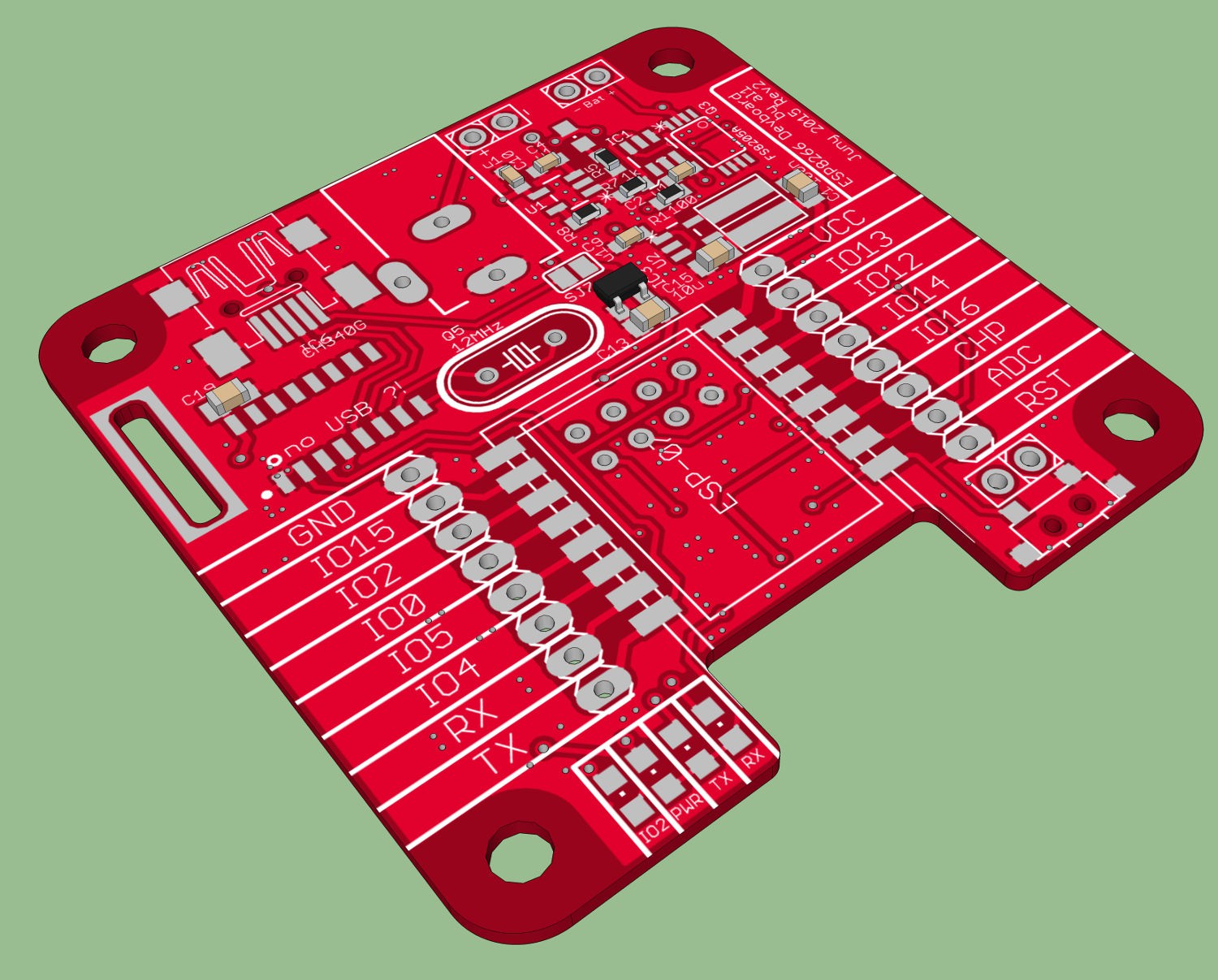
Layouting Rev2 Part 2
06/05/2015 at 21:03 • 6 commentsSo I think its done. This is the Version I will order the next days. As long there are no mistakes.
![]()
I decided to use red solder mask this time. The main improvements compared to Rev1 are:
- You can use now also ESP-01 with this board
- notch under internal antenna so no GND-plane or PCB in the way
- optional user Led connected to IO2
- added missing resistor between GIO15 and GND
- Jumper to disable the LEDs
- bigger (and cheaper) crystal
- and some more minor improvements
-
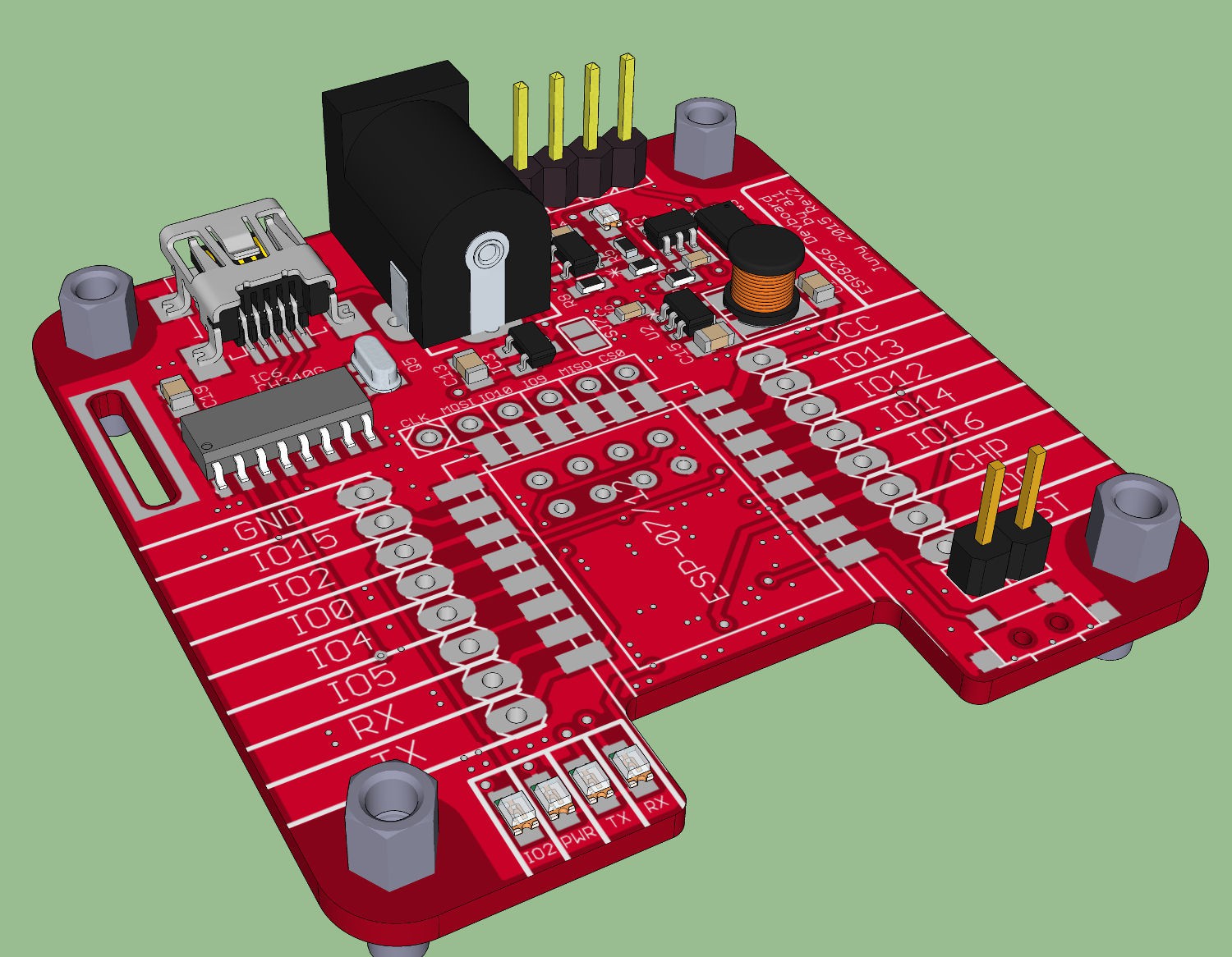
Layouting Rev2
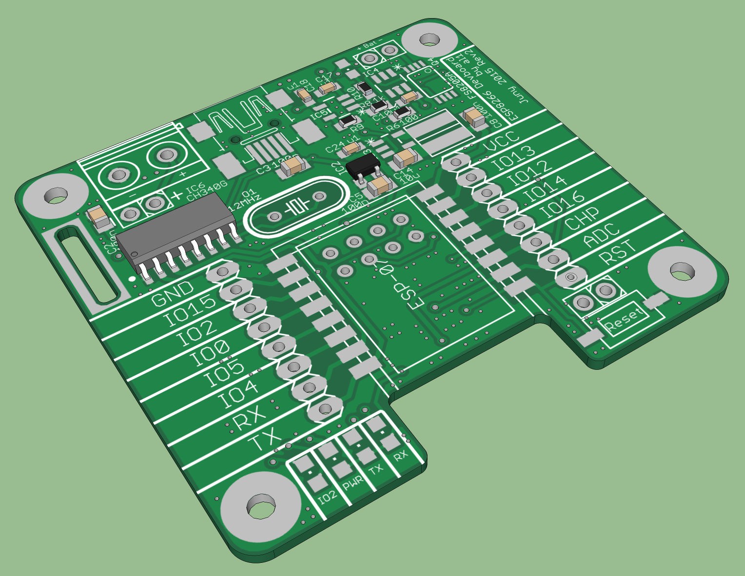
06/01/2015 at 20:40 • 3 commentsAs mentioned before...I am at least layouting an second revision with some bugfixes... Here is a first render of a early Version of Rev2:
![]()
I will not use black solder mask this time. I will use some lighter colour (green, yellow or blue). But I had not decided yet.
-
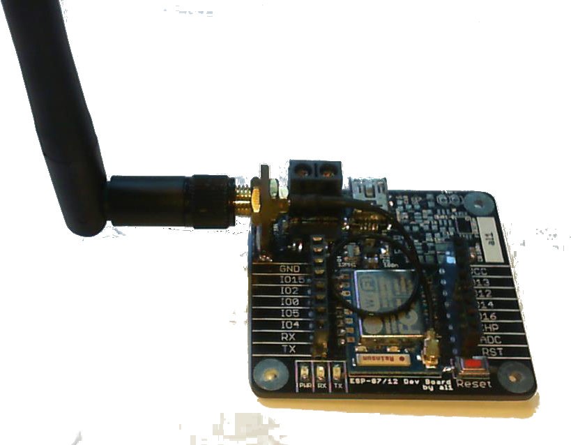
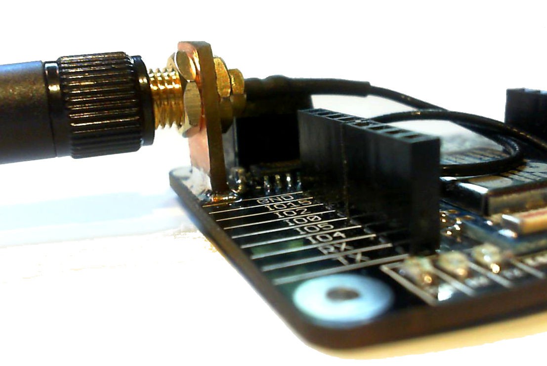
External Antenna
06/01/2015 at 13:45 • 0 commentsYou may have wondered where for this slot on the PCB is. Here is the answer: You can solder a small piece of PCB into it to get a mount for an external antenna:
![]()
![]()
ESP8266 (ESP-07/12) Dev Board
PCB for fast development with ESP-07 / ESP-12 with on board USB to Serial converter and on board lipo charge / protection circuit
 But this does only affect the RX, TX and Power LED so if you are not using any of these LEDs you do not have to worry. The PCBs do work without any modification. If you need the LEDs get a screwdriver and a soldering iron and fix it like this:
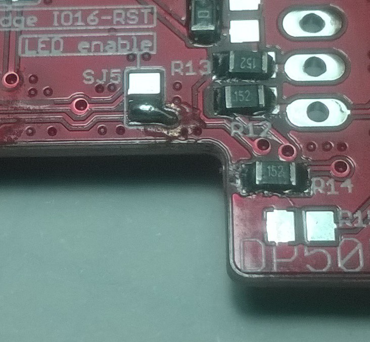
 The PCB has now also Mounting holes for M3 screw (old Rev M2.5) and a power Jack instead of the screw terminal.