-
1Step 1
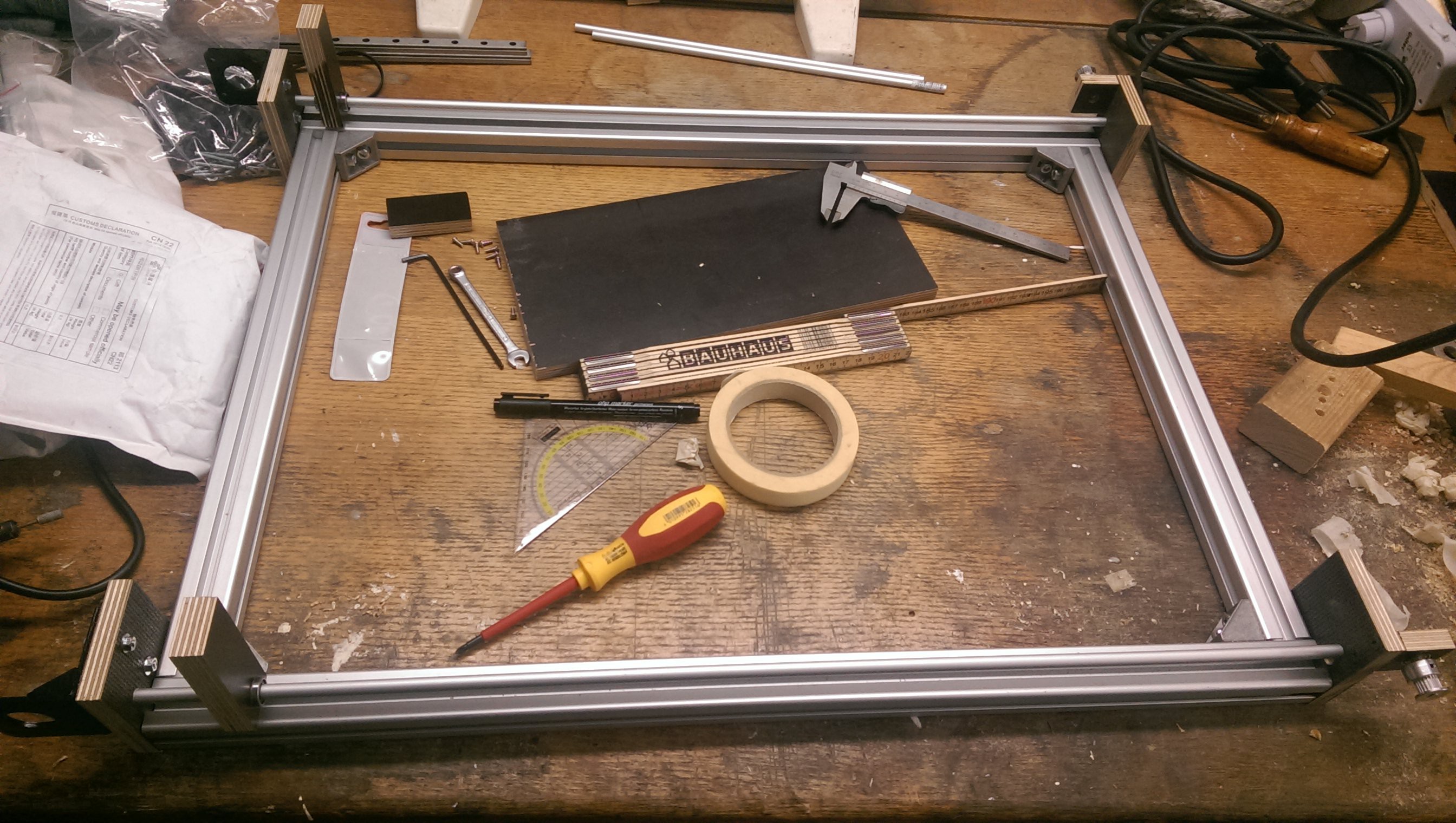
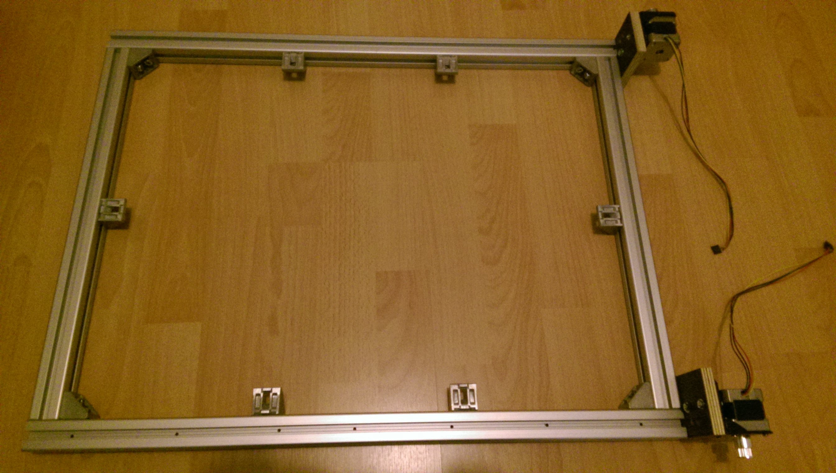
The frame
![]()
![]()
![]()
-
2Step 2
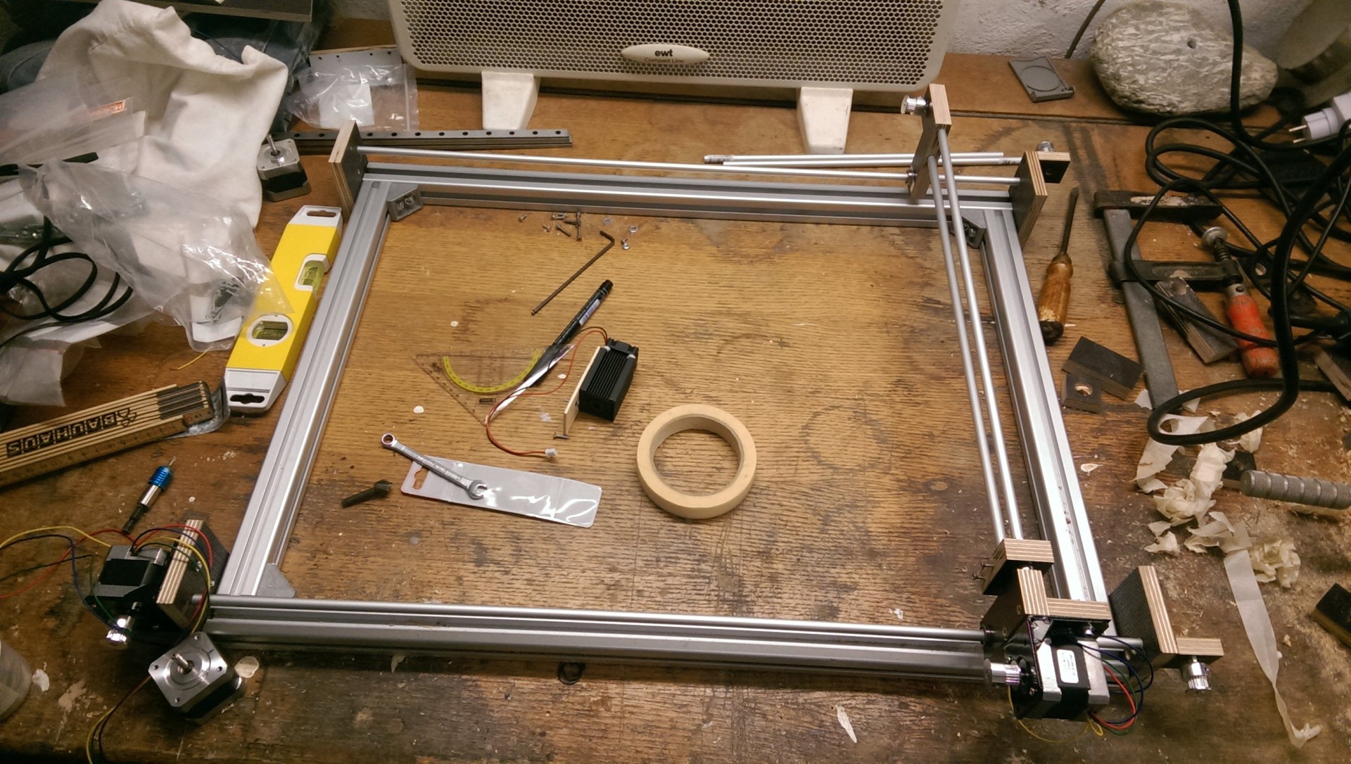
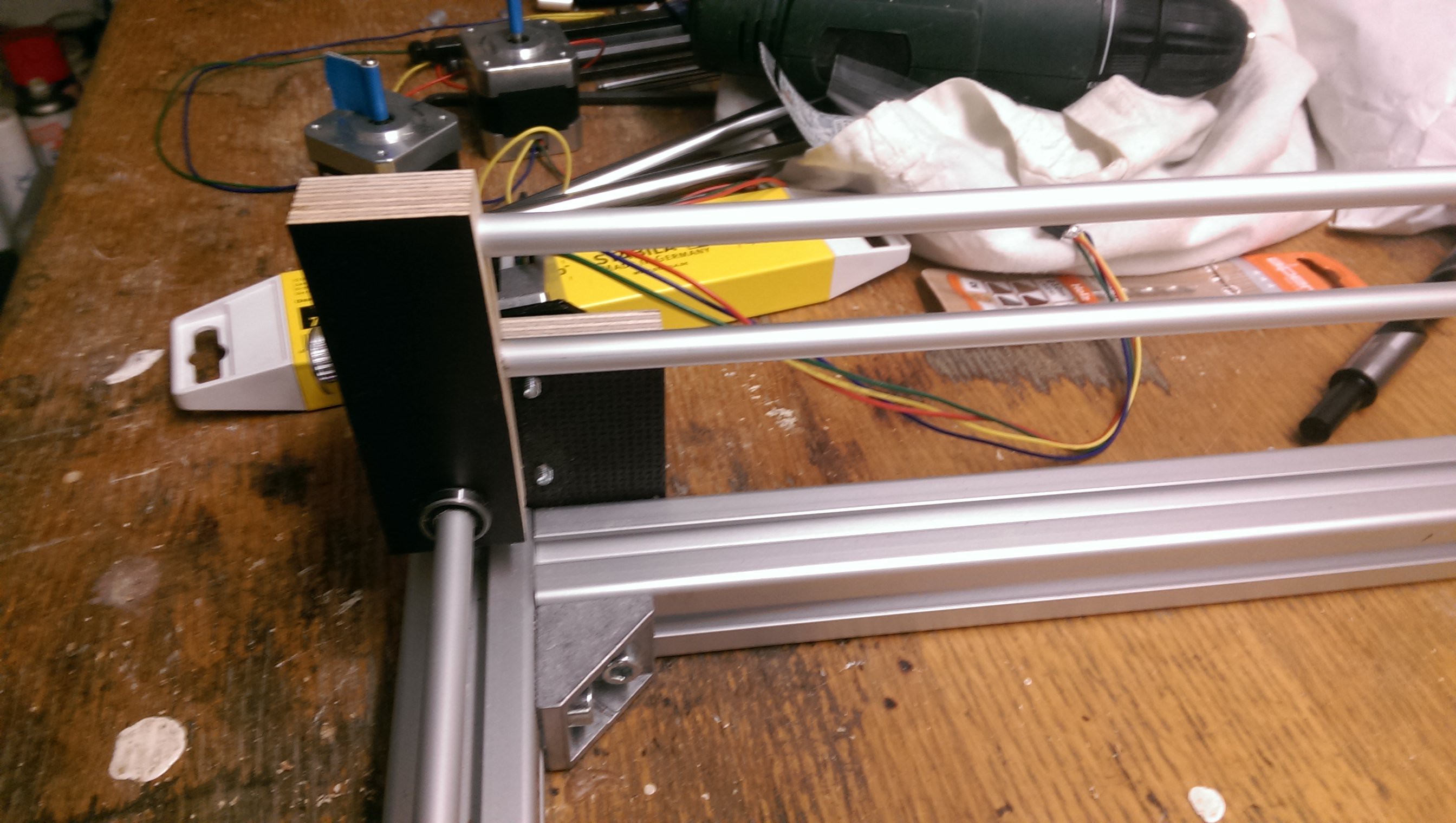
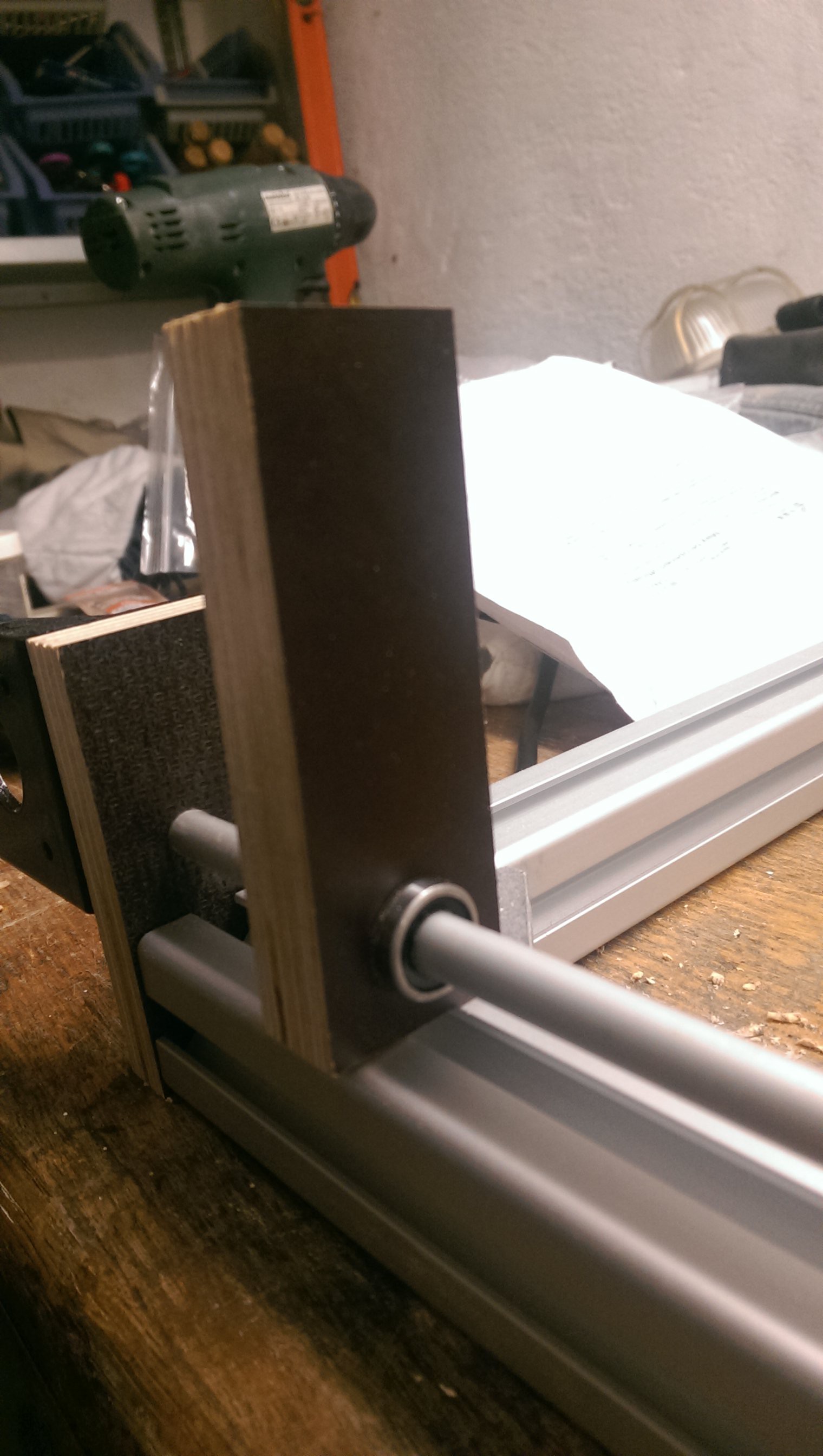
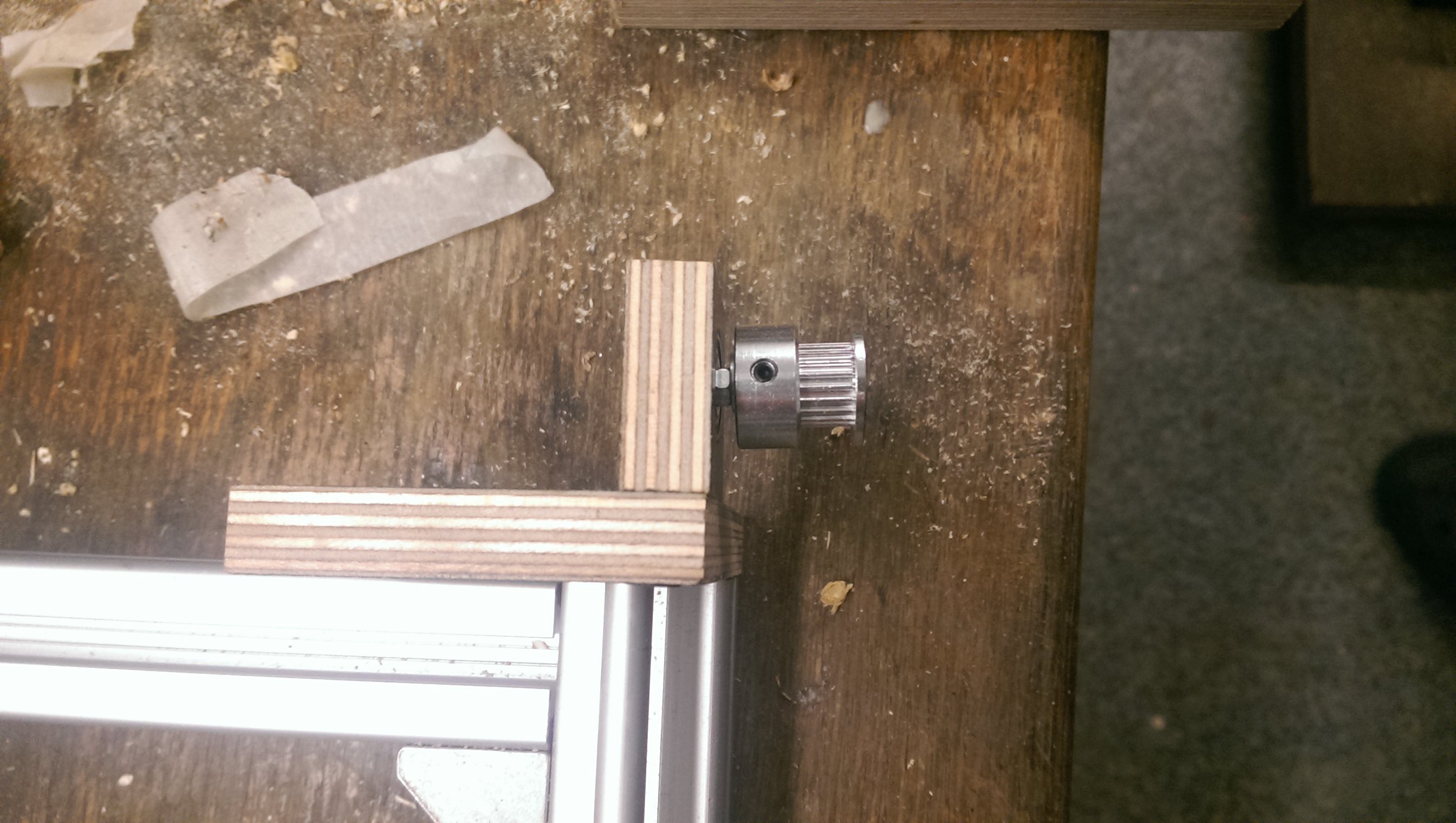
Axis
![]()
![]()
![]()
-
3Step 3
Laser-module and driver
For the laser module I choose a relatively cheep heat sink and a standard 3-layer glass lens (450 nm) and a Osram PL TB450B 1.6 W_opt. 450 nm diode from China. The lens came in a package with the heat sink.
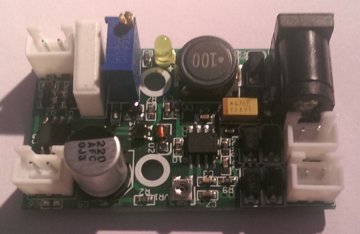
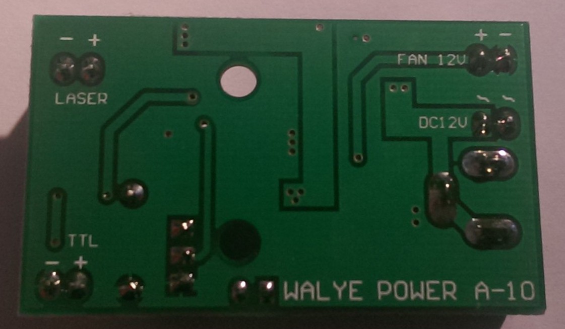
As the power source for the laser I am using a constant current power supply (max. 3W) with TTL support.
First I had to unsolder all plastic sockets from the board since I could not find the matching connectors online. I replaced them with common 2-pol Molex sockets and made my own connectors with cables.
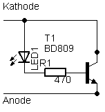
To adjust the current the laser will get, I adopted the idea of a dummy diode from power-LEDs (dummy LEDs).
![]()
![]()
A BD809 was mounted on a good heat sink and a 20 mA LED + 470 ohm resistor was soldered to base and collector of the transistor.
With this dummy laser diode I could adjust the current without risking my Osram diode. The transistor converts all energy into heat, so with 1.2 A @ about 4.2 V which are typical parameters for the laser diode it generated
about 5W of head. There is no arguing about whether that a heat sink is necessary !
![]()
To switch the laser on/off by grbl, I connected the TTL- pin to a common ground with the arduino and the TTL+ pin with a pull-down resisitor to pin11 (grbl 0.9) of the arduino. By variating the spindle spped with the S<number> g-code paramter a PWM signal controls the on/off time of the laser and resulting in <number> % of power.
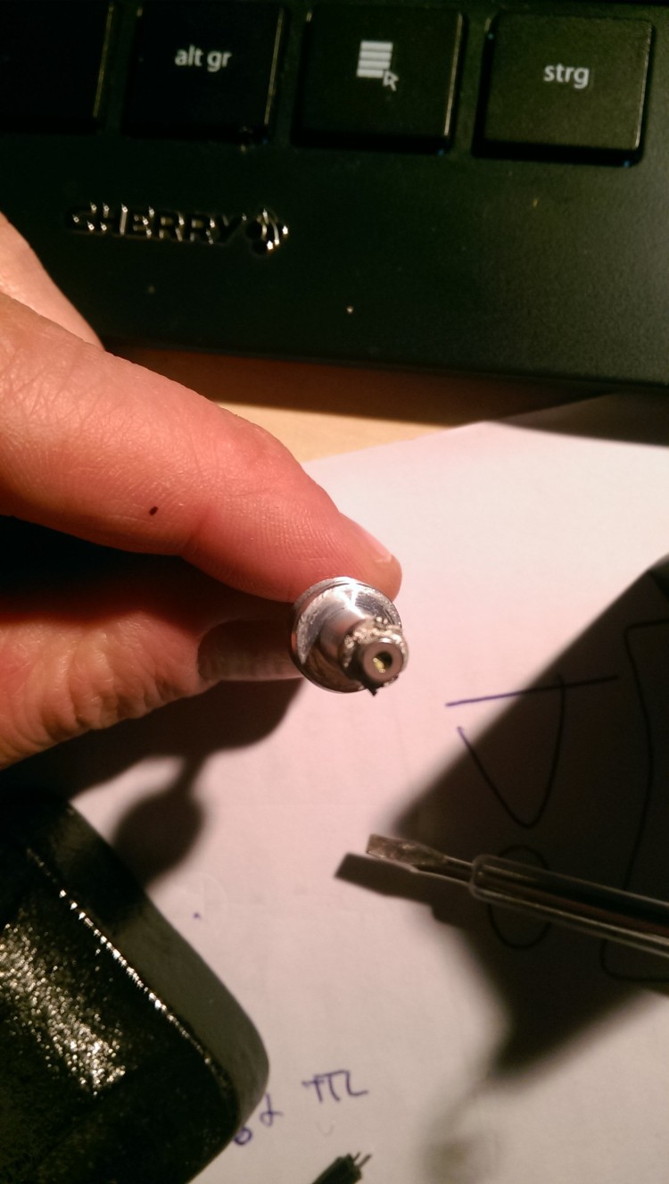
With the power source set up, I began to mount the diode itself into the heat sink. This was more difficult than I thought since there is very little space for the cables and the isolation of the pins.
With the cables finally soldered to the diode, I applyed a tiny amount of silver thermal paste to the diode. The data sheet states, that the main heat dissipation is done by the tiny metal ring around the diode.
![]()
I wanted to be sure the diode runs within thermal parameters (>70 °C).
For active cooling I removed the fan that came with the laser heat sink and mounted a very powerful 4 cm fan on it. This fan not only cools the laser, but also blow all smoke from cutting/engraving away.
So nothing can condensate on the glass lens.
-
4Step 4
Stepper motor driver board
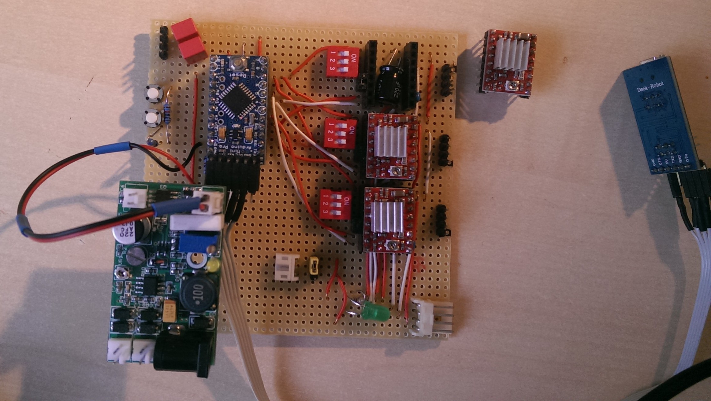
I basically copied the GRBL shield or any other stepper driver board for the A4988 driver there is.
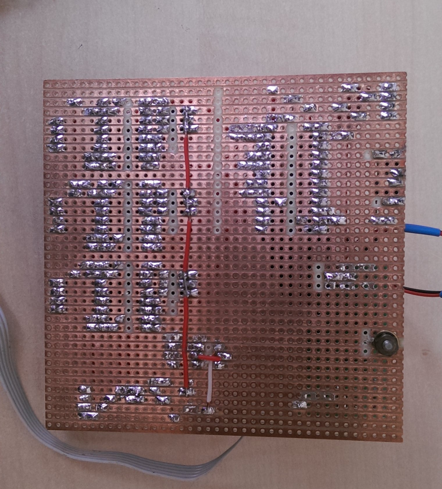
I used BlackBoard 1.1 for the PCB design, neverthless the wireing is horrible ! I am not that into electronics.
After a lot of reseach and a lot of opinions from folks in different forums I decided to install a 220 µF / 35 V and a 0.1 µF for every motor driver module at the V_mot and Vdd pins to reduce voltage spikes from the motor which might damage the driver.
Every module has its own switch to set the microstepping and a general enable jumper.
The momentary switches at the left side of the arduino board are used to resume/stop the machine via GRBL. They are connected to the reset/abord (A0) and resume (A2) pins of the arduino. The TTL-port of the laser driver board in the lower left corner is connected via a 39 kohm resisitor to pin 11 to control the laser power via PWM.
The 4-pin floppy connector in the lower right corner is used for the main power. A computer power supply is connected which feeds the motors and the laser.
![]()
![]()
![]()
-
5Step 5
Calibration
Calibrating the X/Y-axis of a plotter or CNC machine is actually quite easy. I did it as described in this video. First i had to know the theoretical steps/mm per axis. To calculate this value I multiplied
the steps/rev. (200 for most NEMA Motors) with the microstepping of my motor drivers.
200 steps/rev. x 16 microstepping = 3200 steps/rev.
For my A4988 drivers the maximum value is x16-microstepping, so the motor needs 3200 steps to do one full revolution. Next, I had to take care of the specs. of the timing belt. For the GT-2 the pitch is 2mm and 20 teeth pulley.
Now to get the theoretical steps/mm I divided the steps/rev. by 40 and get 80 steps/mm as the starting value.
2 mm x 20 teeth = 40 mm
3200 steps / 40 mm= 80 steps / mm
The correct value will just differ a tiny bit from the theoretical one, it basically depends on the accuracy of the mechanics.
To do this I ran defined distance on one axis. I marked the starting point and the endpoint of the laser with a pen (or burn it into your working area :)) then traveled the longest distance possible for this axis.
The longer the distance is, the more accurate is the calibration. In my case that is 550 mm (g-code X550). Then I measured the distance between the two points. Due to some inaccuracies the distance
travelled is not 550 mm. A slightly shorter or longer distance will be measured. Instead of the 550 mm my plotter moved 557.5 mm.
As we already know the steps/mm, we can calculate the theoretical steps the motor has to take:
80 steps/mm * 550 mm = 44000 steps
But the measured distance was 557.5 mm, so this is as 200 additional steps<p>
80 steps/mm * 2.5 mm = 200 steps
were taken. Subtraction the additional 200 steps from the theoretical value and division by the travelled length gives the correct steps/mm for my machine.
(44000 steps / 550mmm - 200 steps) / 550 mm = 79.6363 steps/mm
Analogously this calculation was repeated for the y-axis and entered into the grbl firmware.
-
6Step 6
Drawing Software and g-code generation
For drawing and editing SVG vector graphics I use Inkscape and the 'laserengraver' plug-in. I will not go into much detail here since there are a lot very good tutorials out there for this.
Just one additional remark:
Since I use the spindle-speed control via PWM to adjust the laser power, I have to add the laser power SXX (for XX% power) at the top of every g-code file (*.nc) according to the material I want to cut / engrave.
This value is highly experimental and it can take quite some to get good results (see next paragraph for details).
G90

G21

G0 X6.5995 Y34.3131
S80 ;This line was added
M03

G1 F50.000000

G1 X3.0872 Y34.3131
The Universal G-Codesender is the software of choice for me to send the g-code files to the grbl firmware. I find the macros (v.1.8) quite handy since you can set them up to help you with the new zero-reset.
I have C1 configured (S0.3M03), 0.3% power, laser on) to give me a weak laser dot, that does not damage my eyes instantly, as an orientation point on the working area. A click on C2
(M05G10P0X0Y0Z0, laser off, reset zero) resets the current position as new zero.
-
7Step 7
Materials I tested so far
Here I will present my initial experiments with different materials, laser powers and feed rates. Before even staring with these kind of experiments, one must be sure that the focal point is correct. Furthermore you have to adjust the hight of the laser according to the thickness of your material by hand.
If the focal point is off by just a view millimetres, all the experiments were just a waste of time (trust me, I wasted quite some time). With the correct focal point the laser power can be reduced and/or the feed rate increased.
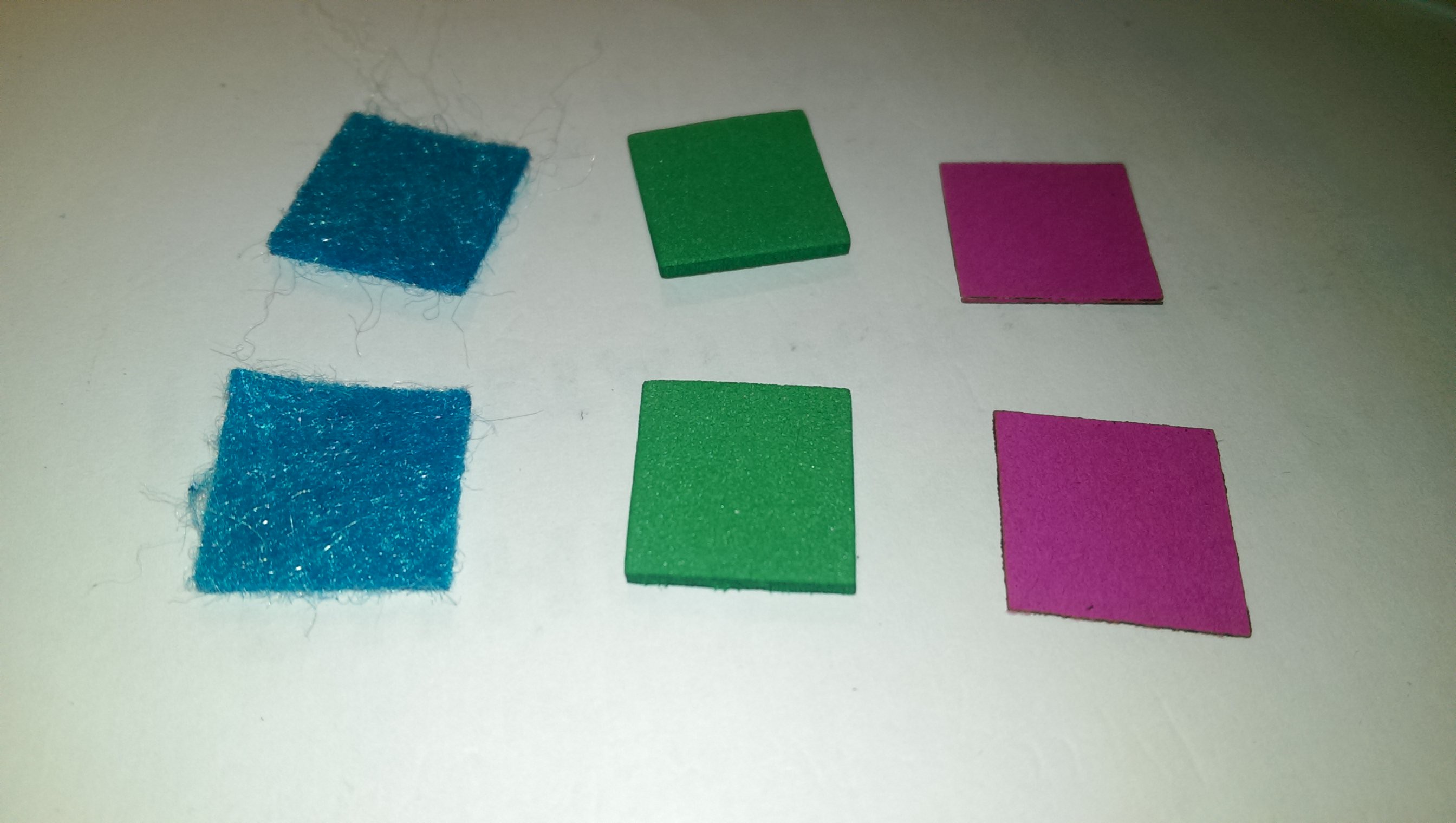
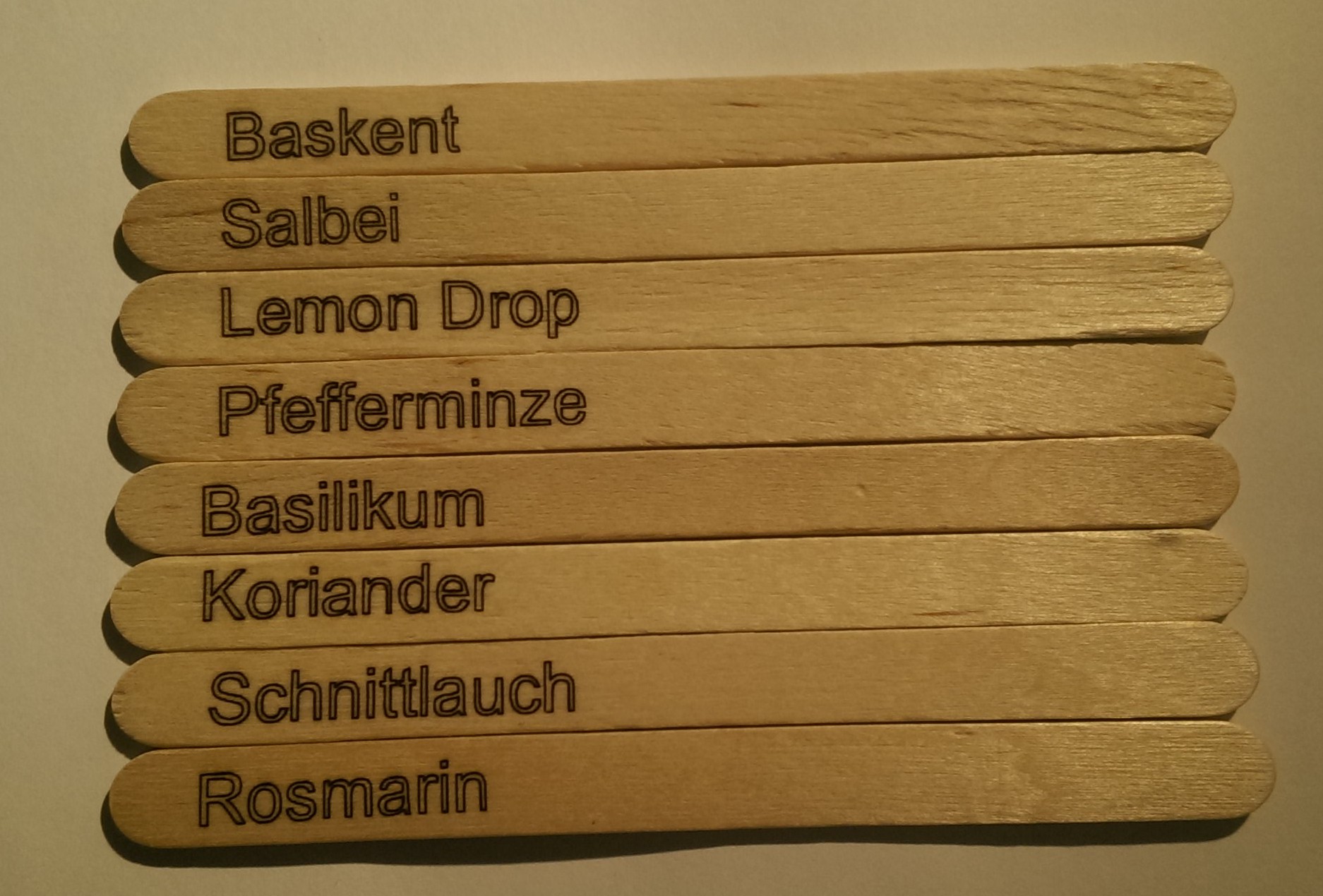
Paper, white, tick S F comment 100 40 way to slow, nice cut but burned surface 90 100 nice clean cut Cupboard, black, thick S F comment 100 100 about 1/4 through, nice kink fold ! 90 50 deep cut, not cut through 100 30 ok but not nice Paper, pink, thin S F comment 100 120 clean cut, can I go faster ? 100 120 Set ! nice cut Felt, 1 mm , blue S F comment 100 100 good cut, some fibres still interhoocked 100 150 too fast Felt, 3 mm, purple S F comment 100 100 Set ! nice cut for straight lines 100 70 Better for cutting patterns, circles etc. Felt, 3 mm, brown S F comment 100 100 Nicely cut, still interhooked fibres 100 90 Same as F100 100 40 Very nice cut, felt molten from laser. Faster? 100 50 Set ! Nice cut and the fastest Foam rubber, 2 mm, green S F comment 100 100 Clean cut => Faster / less power ? 100 130 Clean cut => Faster / less power ? 100 150 Clean cut => Faster / less power ? 100 170 Set ! nice cut Foam rubber, 3 mm, green S F comment 100 100 OK, cutting lines quite broad 80 50 Nice cut 70 70 not cut through Foam rubber, 3 mm, light blue S F comment 100 100 Only partially cut, to little absorbtion ? Ply wood (engraving) S F comment 70 100 Lines to dark / broad 60 150 Nice thin lines clothes pin (engraving) S F comment 60 150 Like Ply wood - Nice thin lines Popsickle (engraving) S F comment 70 150 Too fast, to little power 80 150 better, too fast at streight lines 70 120 * 70 100 * 90 170 * 90 160 * 80 50 good, but only partially => more power 100 70 Nice thin lines *: Due to the texture of the hard wood the laser engraved only partially ![]()
![]()
Yet another laser engraver / cutter
I build a 1.6 W 450 nm laser cutter / engraver mostly from China parts.

Discussions
Become a Hackaday.io Member
Create an account to leave a comment. Already have an account? Log In.
Hello, I really like your project especially the laser diode protection. However, there is one part I don't really understand. Can you share with me about the laser diode connection with the power transistor BD809 ? Is the -ve of laser diode connect to emitter of BD809 or common of BD809?
Are you sure? yes | no
@wongkaikit95: You may understand something wrong. The transistor is connected instead of the laser diode. See the schematic above.
Regards
Are you sure? yes | no
hi , thanks for sharing this neat project, however I've been trying to use GRBL 1.1f version (which has laser mode feature) to engrave with my 100 watt CNC laser , but the engraving speed so slow and increase the feed rate is not affected so much , may I have your advise how to reach to maximum possible speed ?
BR
Are you sure? yes | no
Hey,
have you calibrated your plotter correctly (microstepping, axis length steps / mm, acceleration (important !) etc. ?) Normally if you change the feed rate, the motors _must_ move more quickly. Maybe the motor driver can not handle the fast pulses from grbl ?! I guess you bought a laser plotter with software ? Or is it complete DIY ? If you have a software I would try to control the machine with that an see if you still have the speed issues. If not the problem is with GRBL and your hardware.
Do you have a blog / page whatever with pictures ? I am curious what your plotter looks like :)
regards
Are you sure? yes | no
dear dechemist, i've an issue with my 2w blue laser 12V, bought in china with a Good Laser A-11 driver. This driver is next generation of Walye you show. I've recently upgrade to GRBL 1.1f on Arduino UNO. I'm very ignorant in this topic, thus i need help. I use a IRF 520 Mosfet to control de laser via M3 and M5. It works fine. But when i connect direct from the A-11 driver the power inthe laser is higher than using mosfet. I had connected pin11 (wich controls Mosfet) to TTL + and TTL- to ground and the laser is On, as in direct connection. I've measured voltage in direct connection 5,5 V and more or less the same through mosfet. I want to use TTL but i want to get the maximum power in the laser. Can you help me? Of course i have done nothing on the A-11, like current or voltage regulation. (sorry my english)
Are you sure? yes | no
Hey,
I am really sorry for the long response time ! I must have overseen the eMail notification. You probably already solved your issue but I will answer it anyway. The MOSFET you are using is not fully "open" at the voltage you are applying (5.5 V). So you measure a lower voltage since they kinda act as a resistor. When working with 5V-logic like your TTL signal, use logic level Mosfets, at 5.5V they are fully open (see explaination: https://arduinodiy.wordpress.com/2012/05/02/using-mosfets-with-ttl-levels/)
regards
Are you sure? yes | no
Thanks for your help!To set driver I will use the method with BD809.I have the same drivers and 2W M140 blue laser diode.How to connect BD809-kathode to (-) from laser output and anode to (+) from laser output?
Are you sure? yes | no
Hey, to answer your question: If you want to set the max current for your laser first set the PWM to 100 %, then connect the ampere-meter (set to measure current not voltage !) in series between the power supply and the laser diode. That means one clamp vom the ampere-meter is connected to the power supply the other is connected to the wire of the laser diode. The second (e.g GND) wire from the laser diode goes directly to the power supply. Before you switch on the power supply make sure that it is set at the lowest output, then switch it on and carefully increase the output current to the max current of your laser diode.
Are you sure? yes | no
Hello,
I am a beginner in laser engraving. How must be connected ampere meter for setting laser diode driver max output current? If it is possible, add connections scheme.
Are you sure? yes | no
Hey,
thanks for your comment. I will see if I manage it to do some engraving examples this weekend ! I have to buy new plywood boards.
Are you sure? yes | no
The best engraving with a diode laser
We would like to give 50 USD as a special prize for the best engraving using 2W or 3.5W
diode laser
http://endurancerobots.com/products/laser-cutters-accessory/laser-cutter-accessory-engraving-samples/
Not necessarily Endurance L-Cheapo.
Please send your pictures to gf@endurancerobots.com or place them in our facebook group: https://www.facebook.com/Endurance-1399951053640252/?pnref=lhc
Are you sure? yes | no
Hey, how come you still advertising your page but not adding my photos I send you ? Are they not good enough or is the laser not powerful enough ? At least an answer to my mail would have been nice ;)
Are you sure? yes | no