Capt. Flatus O'Flaherty ☠
-
Balancing the Torques on the Drive Motors
04/22/2018 at 09:21 • 0 commentsAlthough the steering geometry is now pretty much spot on, it does not take account of the instance where one wheel drives over a large rock, effectively travelling a greater distance. Having current sensors on the drive motors would enable final adjustments to be made to keep the motors in sync.
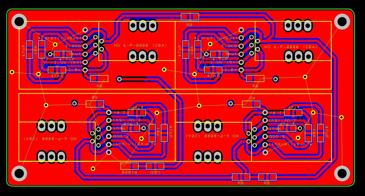
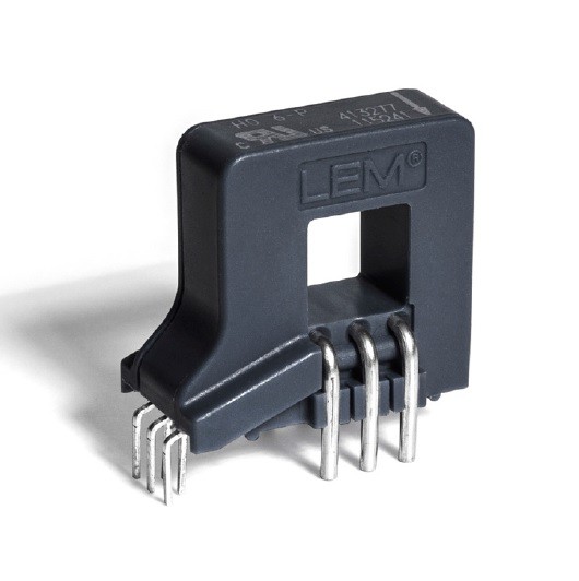
The sensor chosen was the LEM HO 6-P-0000:
![]() A PCB was designed using the suggested layout in the datasheet:
A PCB was designed using the suggested layout in the datasheet:![]()
.... And ordered from JLCPCB for a total of $9 including postage.
There is a good argument for not using such sophisticated motors and drivers, but in the long run it's going to be really useful to be able to move quickly and accurately from one 'grid' of plants to the next without having to worry about positioning errors.
-
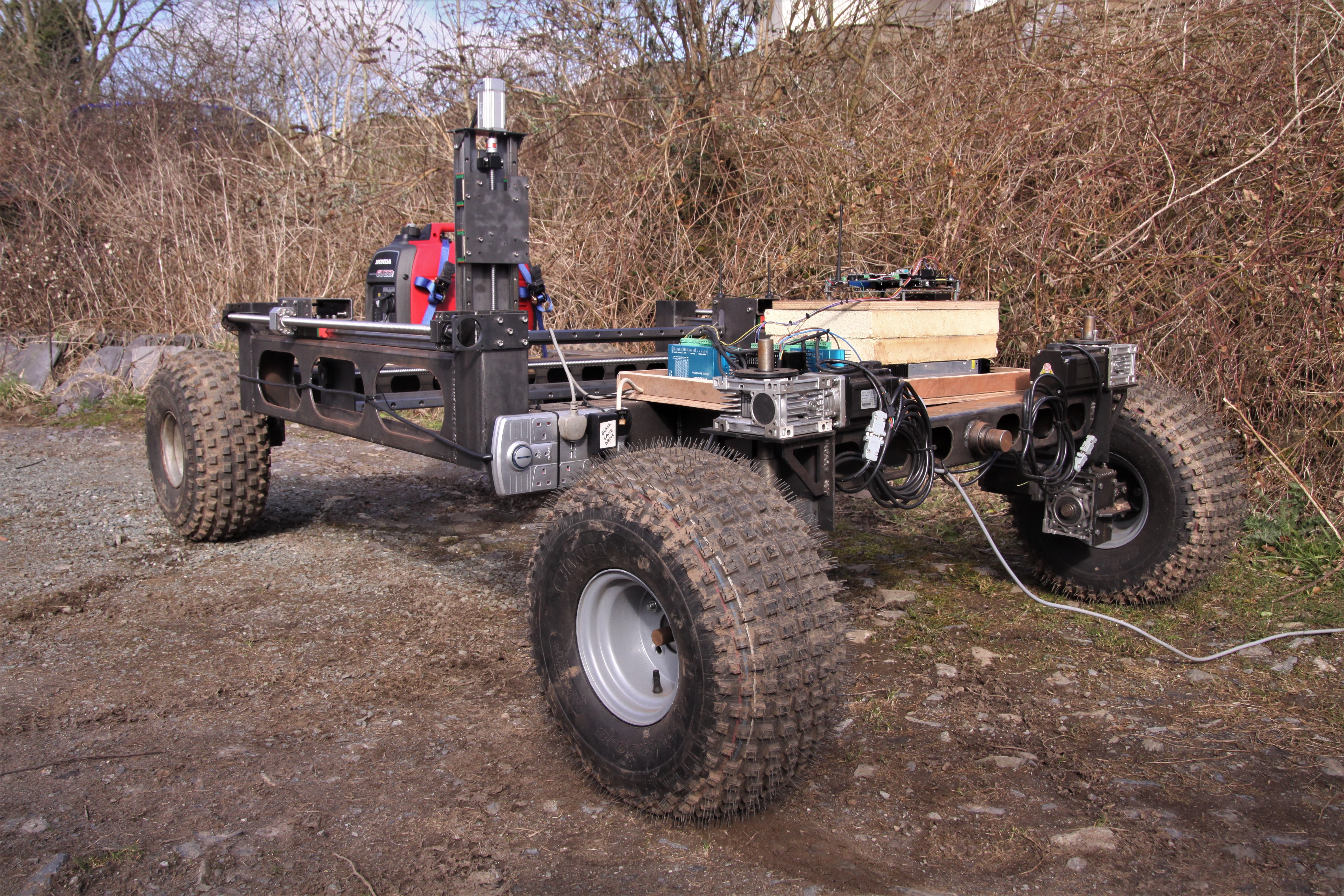
Steering and Drive Now Synchronised
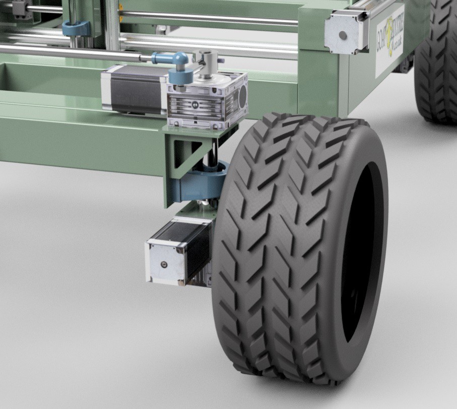
04/17/2018 at 07:38 • 0 commentsDue to the 'offset' nature of the steering geometry, the steering and the drive motors need to be synchronised so that they don't grind against each other or grind on the ground itself.
![]()
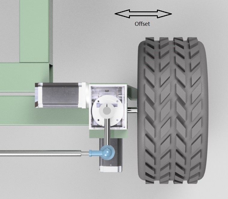
The reason why the steering is offset to start with is that it's much simpler and easier from a mechanical point of view to build it like this and also much cheaper to build. Whilst most cars on the road would have the steering axis much closer to the middle of the wheels, a lot of four wheel drive tractors have the steering offset as in the picture below:
![]()
Since we are using electric motors and have a very sophisticated 'position mode' control system with optical encoders, we can create formulae to take account of the non-ideal steering geometry.
It took me many hours to work it out - but eventually I split the problem into two parts - 1. When the machine is stationary and 2. When the machine is moving. But before I go into how the steering works I need to explain a bit about the control code.
The motors themselves are given pulses from the MCU to step forwards and the pulses are generated every time a specified interval passes in the main control loop. This is similar to the familiar 'blink without delay' except that here there are four intervals running synchronously and I use 'micros' instead of 'millis' and the MCU is a super fast TC275 rather than an Uno or Mega. In terms of units, the interval is 'seconds' and speed is 'something per second':
... And in practise this means that we can't just add different intervals together to get speed.
Back to the machine ...... When the steering needs to turn AND when the machine is stationary, the tyres will grind across the floor unless they actually turn very slightly during the steering motion. In theory, the formula should just be based on a simple ratio of the radius of the wheel to the radius of the steering offset, but in practise there are other factors which require the ratio to be adjusted by a factor of 2. Also, when the steering turns in this 'stationary' case, one wheel needs to turn slightly forwards and the other slightly backwards!
In my code, 'intervalThree' gives the right hand motor speed and 'intervalOne' the RH wheel steering speed and the formula for steering when stationary is very simple:
intervalThree = intervalOne * radiusRatio * 2
This formula was tested on the machine and I could see that the torque on the drive motors did not significantly change whilst steering ..... Success!
When the machine is actually moving, the formula is a bit more complex as we need to add speeds together. Essentially, we need to add the speed calculated as above to the speed of the drive motor at any given time, ie wheel speed + steering speed x radius ratios x 2 ..... BUT our units of speed are in 'per second' so we have to invert the speeds first. The actual formula looks something like this:
intervalThree = 1/((1/intervalThree) + (1/(intervalOne * radiusRatio * 2)))
This formula was uploaded and checked on the machine itself by monitoring the torque on the two front wheels. The torque reading are now both stable, without the large fluctuations that I was getting previously ..... Success - the formula works!
-
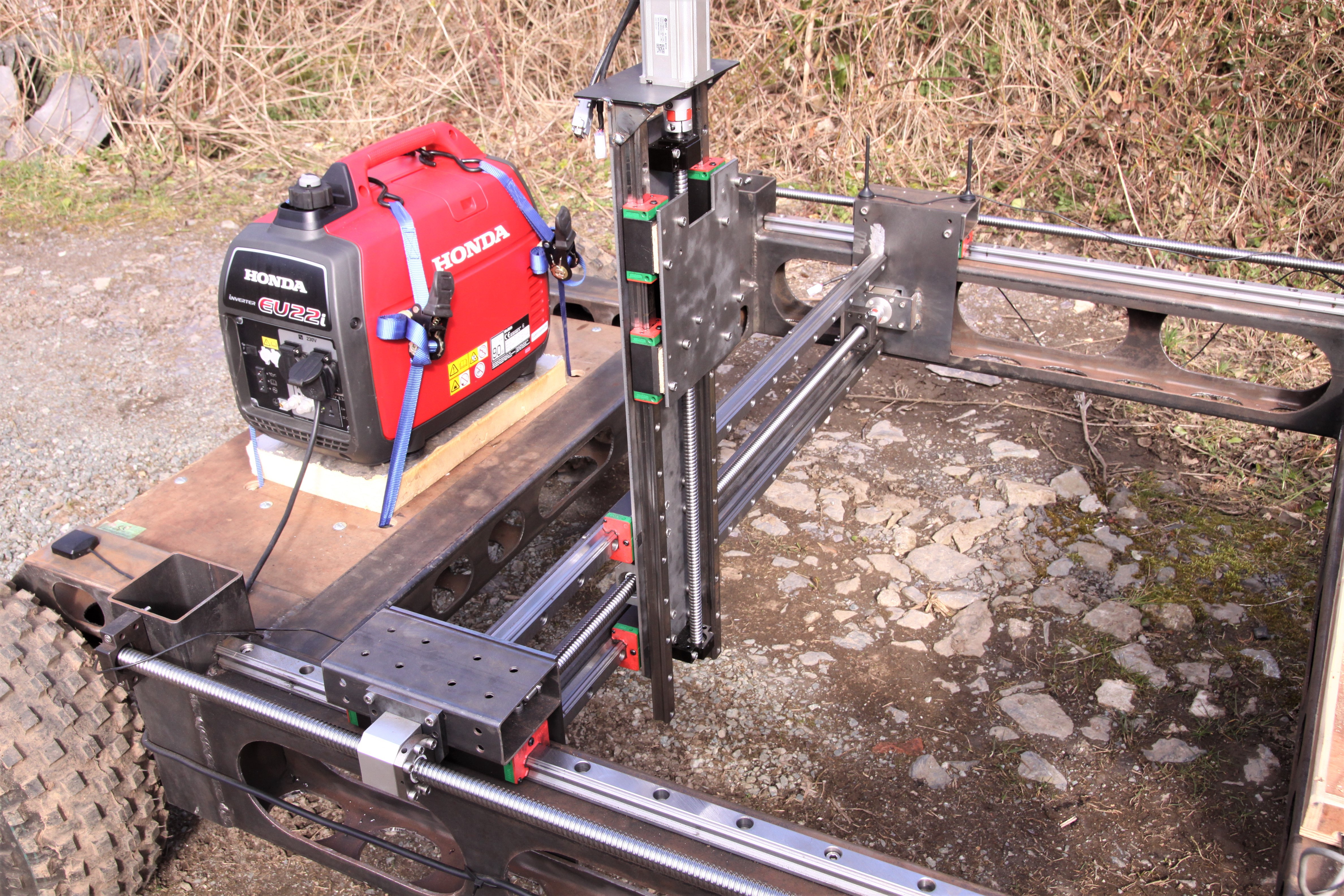
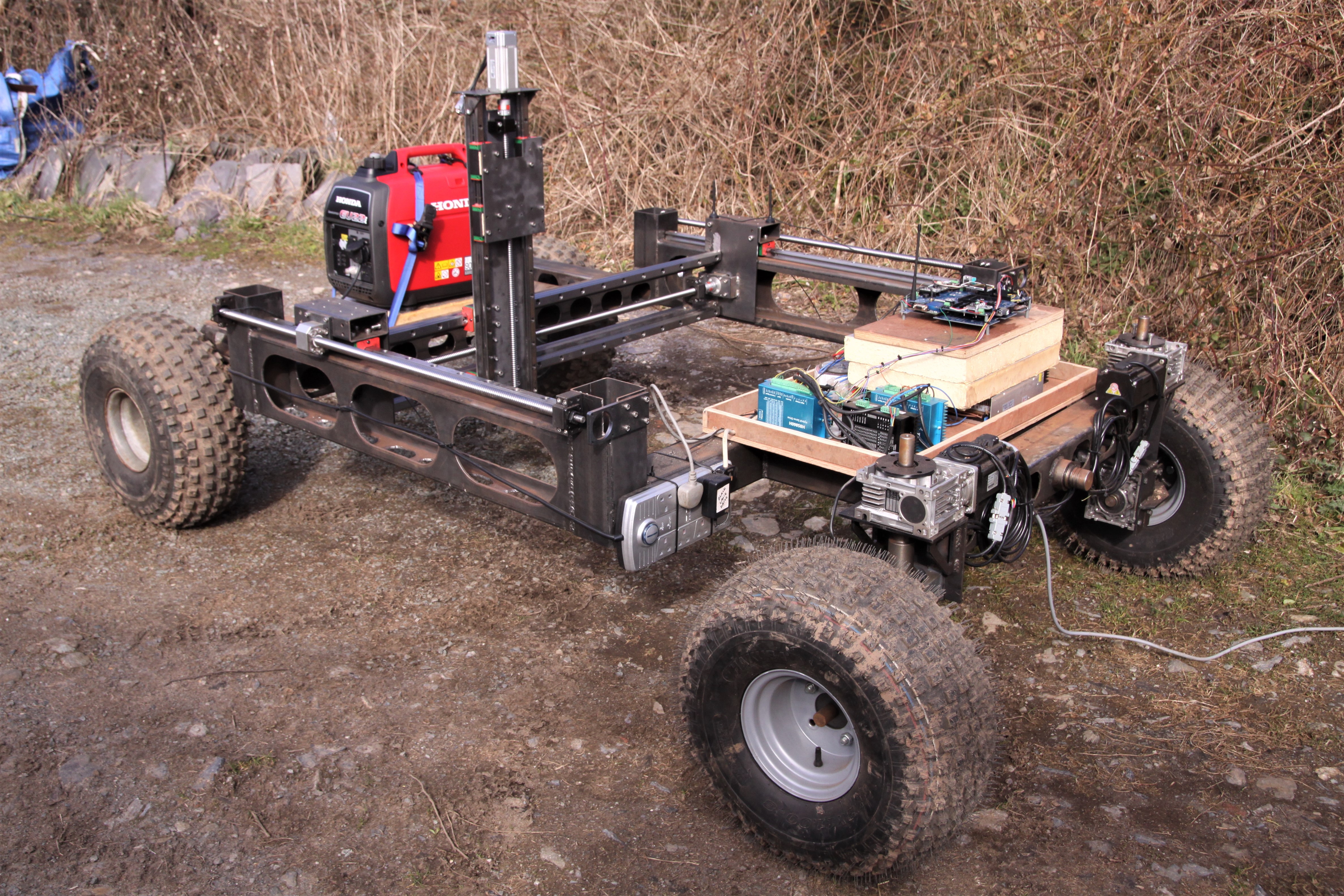
Upgrading Main Drive Motors and Demonstating CNC Mechanism
04/15/2018 at 10:55 • 0 commentsThere's been a lot of work on the WEEDINATOR mechanics this week, mostly trying to tune the motor upgrade from steppers to 750 watt AC servos. It took me a couple of days to work out that most of the attention needed to be focused on the steering algorithm rather than the motors themselves - the machine worked fine when moving in a straight line, with adequate power and plenty of speed, but threw up current overload errors when negotiating tight turns.
The drive now uses two of these motor and driver kits, bought from Fasttobuy, China:
Leadshine ACM8008L2H + L5 750, NEMA32 0.75KW 220V High Speed CNC Servo Control 2.4NM
2500line AC Servo Motor and Driver L5 750 + cablesI would have preferred to use brushless DC servos but I could not find anything affordable above 400 watts. One of the advantages of using DC power is that there would be less strain on the generator due to fluctuating power demands as small batteries can be used as 'capacitors' to provide extra amps during heavy demand. I might try temporarily swapping in the 400 watt Nema 23 motors that I'm currently using on the CNC, just to see how they behave.
The CNC mechanism uses this motor and driver kit, from the same Chinese supplier:
Leadshine Brushless ACS806 + ACM604V60-30-2500, 20-80V DC 400W servo motor + drive + cables
The following video shows some of the success achieved with the CNC mechanism and a more in depth description of the drive motor and steering tuning issues with proposed solutions:
-
App for setting waypoints is started
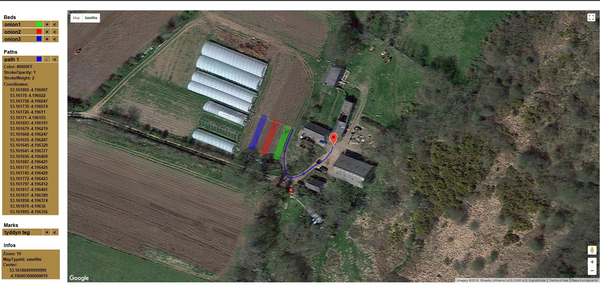
04/13/2018 at 06:47 • 0 commentsRather than just having a clunky database for storing all the waypoint coordinates - why not have a green and pleasant Google maps based system where we can almost see the crops growing?
This is exactly what our team member Rafael Neves has done here: https://farms-geogad.netlify.com/
![]()
Now we have to get it linked to the database using MYSQL.
-
Object Recognition Up and Running
04/01/2018 at 16:36 • 0 commentsUsing the Pixy (CMUcam5) I managed to get the WEEDINATOR to follow 'breadcrumbs' as an aid to navigation. Yellow discs were thrown down in front of the machine to help guide it to GPS waypoints.
-
Autonomous Steering Now Working!
03/28/2018 at 18:08 • 0 commentsAfter several days of debugging the GPS module and getting 1 Hz refresh rates, I finally managed to get the control system stable enough to do a proper test on the autonomous steering:
-
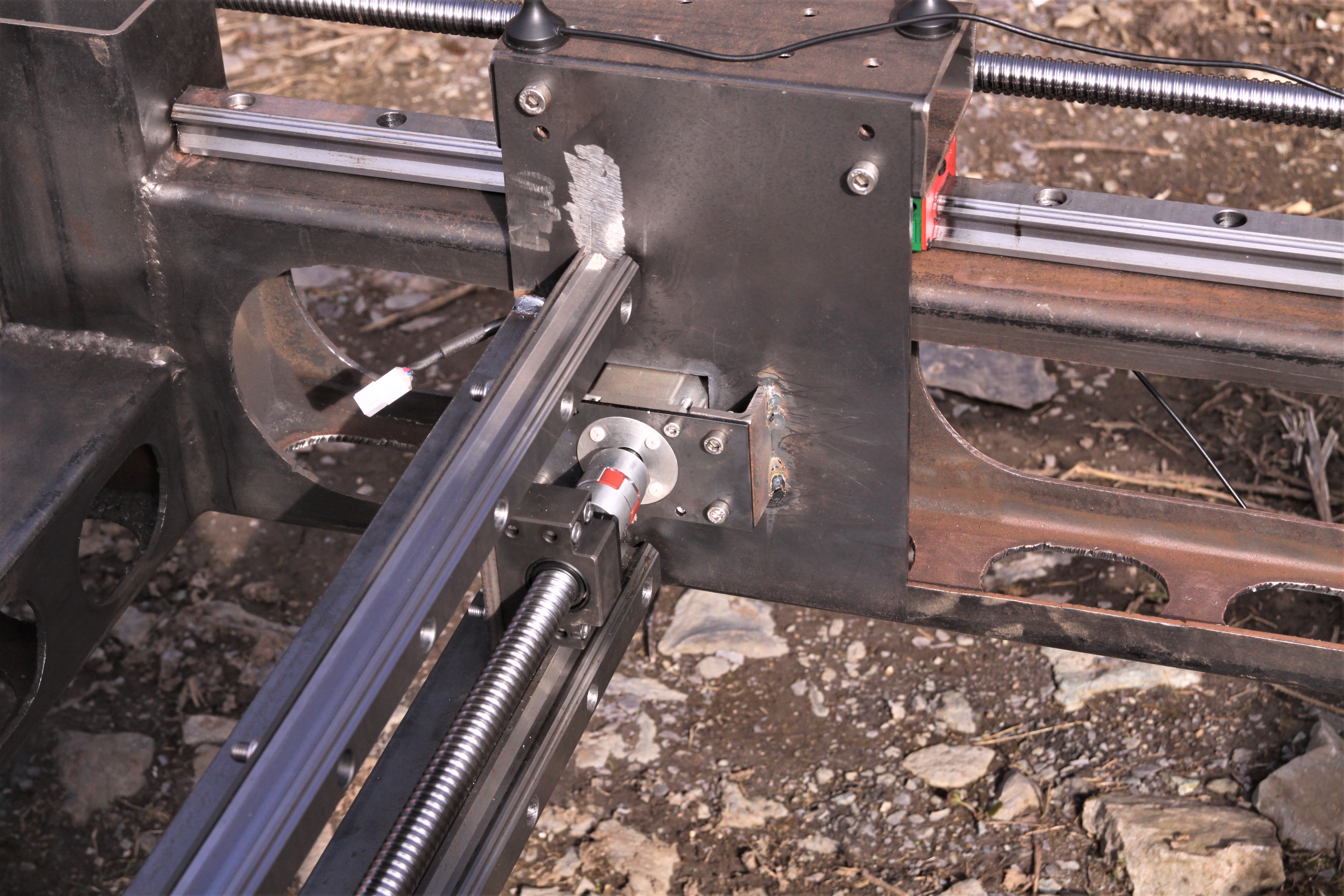
CNC Mechanism Nearly Completed
03/26/2018 at 11:08 • 1 comment![]()
And just to remind ourselves of the build process:
![]()
Strangely, it's actually looking very similar to the CAD design.
![]()
![]()
![]()
![]()
Although the CNC build went quite smoothly, I did make one critical error by getting the Z axis ball screw out by 20 mm. It really has to be correct to about +- 1mm. Optimistically, I took the screw and nut assembly to my friendly local machinist to remove 20mm and we looked at the nut quizzically. It would not fit in the lathe with the nut on. Should we remove it? After some debate, we decided to remove the nut, aware that a load of bearing would fall out which would need to be captured and replaced after the machining was finished. We successfully caught all the bearings, but could I get them back in again? I tried for several hours but no success. Fortunately, I've got another delivery from Fasttobuy in the offing, so managed to get a replacement screw and nut kit for $30 and no additional postage. Hopefully it will now be the correct length from the factory.
Replacement ball screw kit and additional motors should arrive early next week together with some drive motor upgrades so should be able to make the machine drive a lot faster!
-
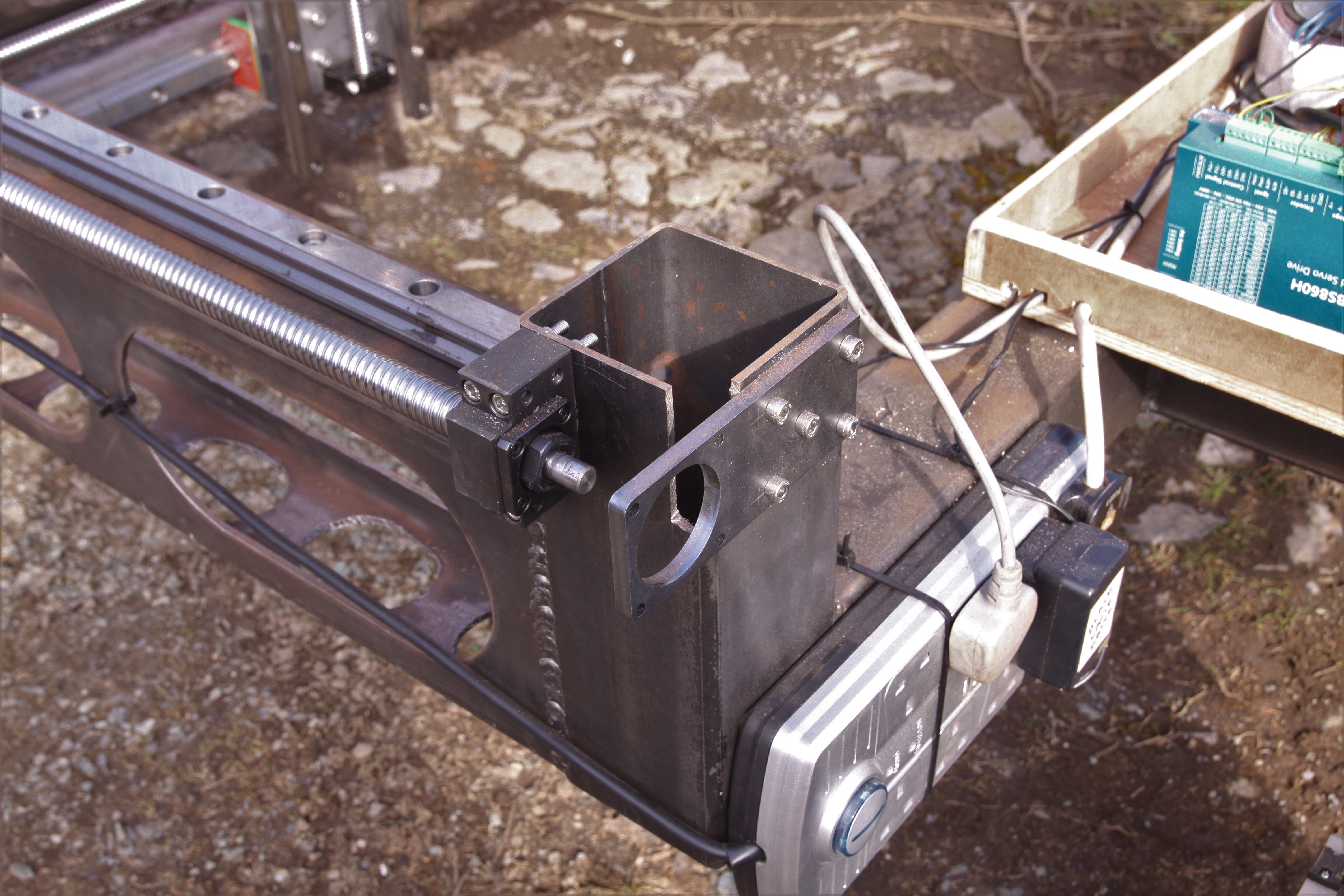
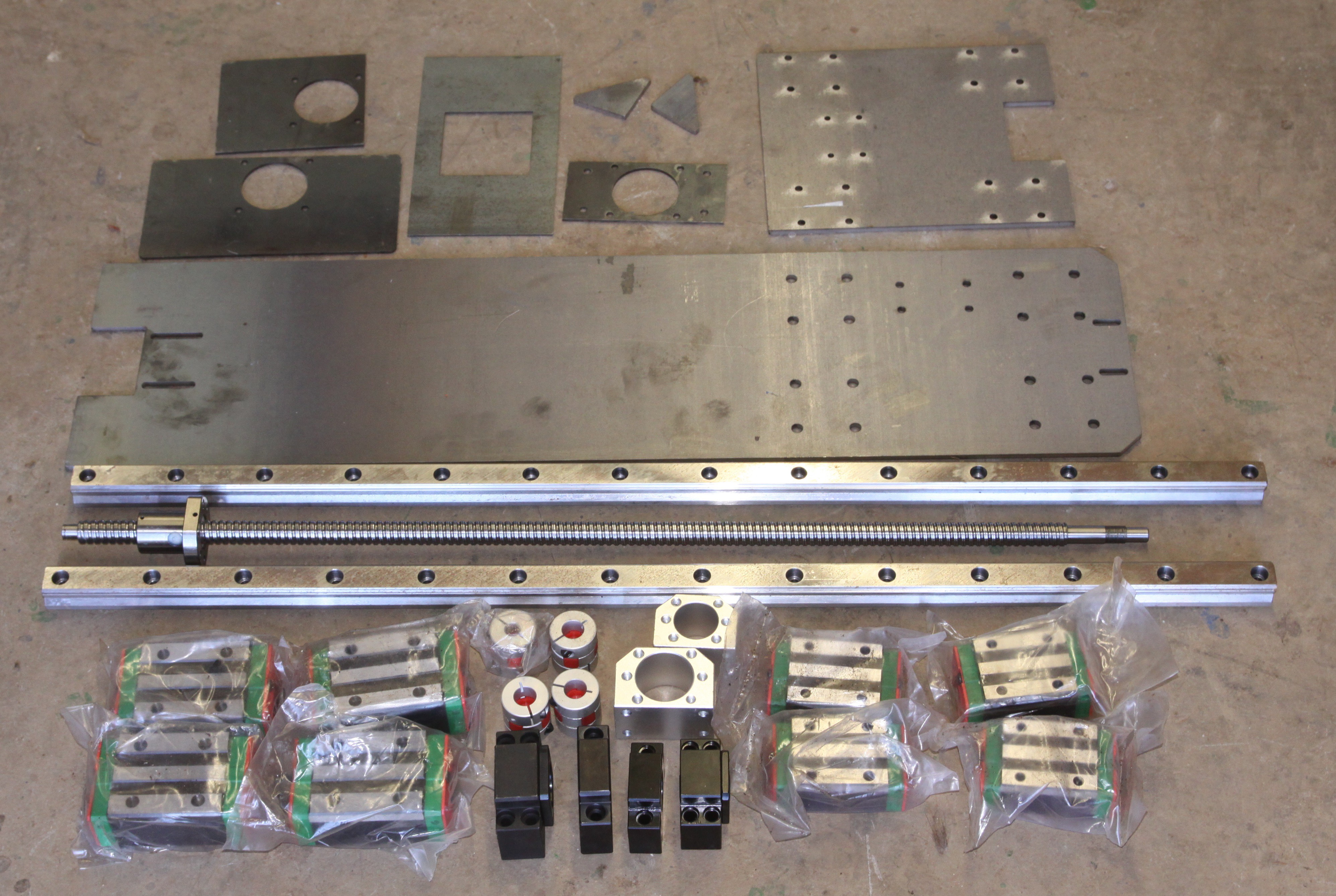
Main Body of the CNC to be Assembled
03/23/2018 at 08:21 • 3 comments![]()
I had planned to build the CNC later on in 2018, but I just could not restrain myself! Previously, two saddles were installed on the 200 x 100 box section for the X axis. With some extra rails and ballscrew for the Y axis (Not shown) these are the components to finish the CNC build (Motors not shown).
-
Testing CNC X Axis Motors
03/15/2018 at 09:07 • 0 commentsThe WEEDINATOR, if you did not know already, is an autonomous roving CNC machine that travels around a farm weeding beds of vegetables. The actual weeding mechanism is similar to a woodworking router, but acts on soil not wood.
I tested the X axis motors with a 100 kg spring balance thinking that it would never pull more than 50 kg ..... How wrong I was! It easily pulled a full 100 kg on the ball screw with ample capacity to spare. The Leadshine ACM604V60-01 brushless DC motor is rated at 400W, 8.6 amps and only pulled 1.7 amps at 48 volts during the test. I reckon it could create as much as 500 kg at full wack.
If you want to use these motors, the best place to buy them is https://www.fasttobuy.com/ where you get good prices, excellent service and fast delivery. The motors do need to be set up properly with the Leadshine Pro Tune software, so don't forget to buy the serial cable to connect to a PC.
-
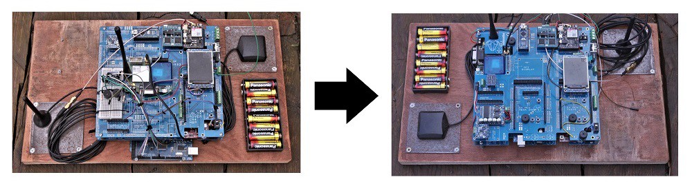
Control Board Upgrade
03/13/2018 at 16:04 • 0 comments![]()
Debugging is an ongoing process, trying to spot the idiosyncrasies of this machine and make appropriate improvements, but basically, it works pretty well now.
Not all PCBs are made equal ...... I've had some made from some companies where the screen print has been off by as much as 2mm which makes populating the boards very difficult, especially on small 0402 stuff.
$2 PCBs & Big Discount on First order Shipping: https://jlcpcb.com
WEEDINATOR 2019
The WEEDINATOR project continues .... The inevitability of robots working on farms draws ever nearer ....
 A PCB was designed using the suggested layout in the