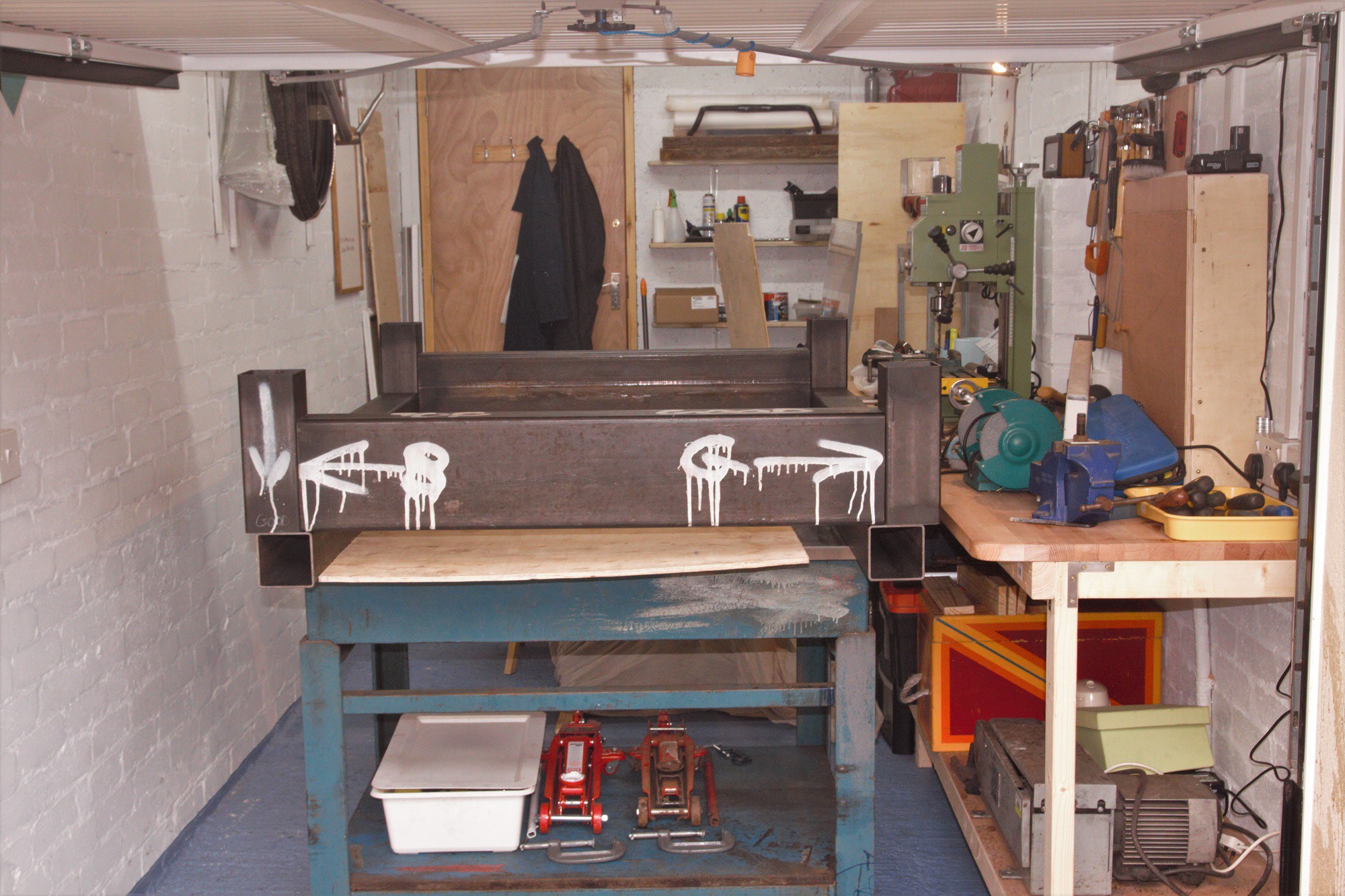
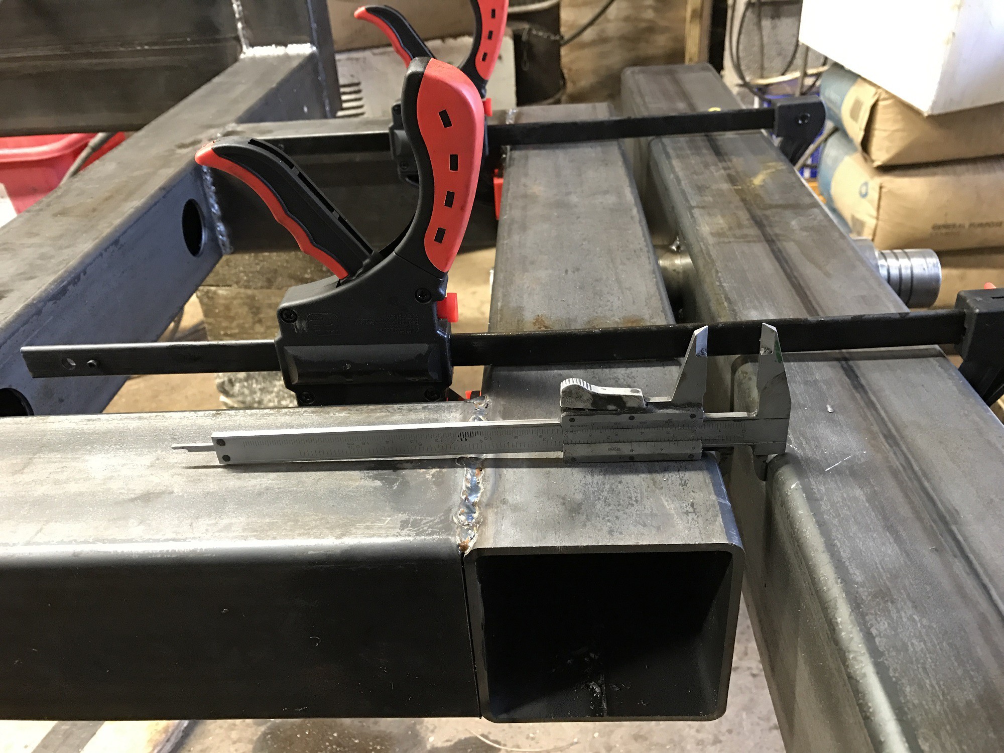
The central part of the chassis, which is also going to be the CNC machine, is laid out on an extremely flat surface plate so that the pieces of box section can be positioned as accurately as possible, enabling the CNC components to run nice and smoothly. The pieces are welded up on the table taking great care not to get hot splatter on the table itself, which would ruin it.
The box section itself needs to be cut with an accuracy of about 0.2 mm and I chose the best steel supplier in my location with a saw that used automated feed to get an accuracy to 0.1 mm. Other steel suppliers cut to +- 5mm which is useless!
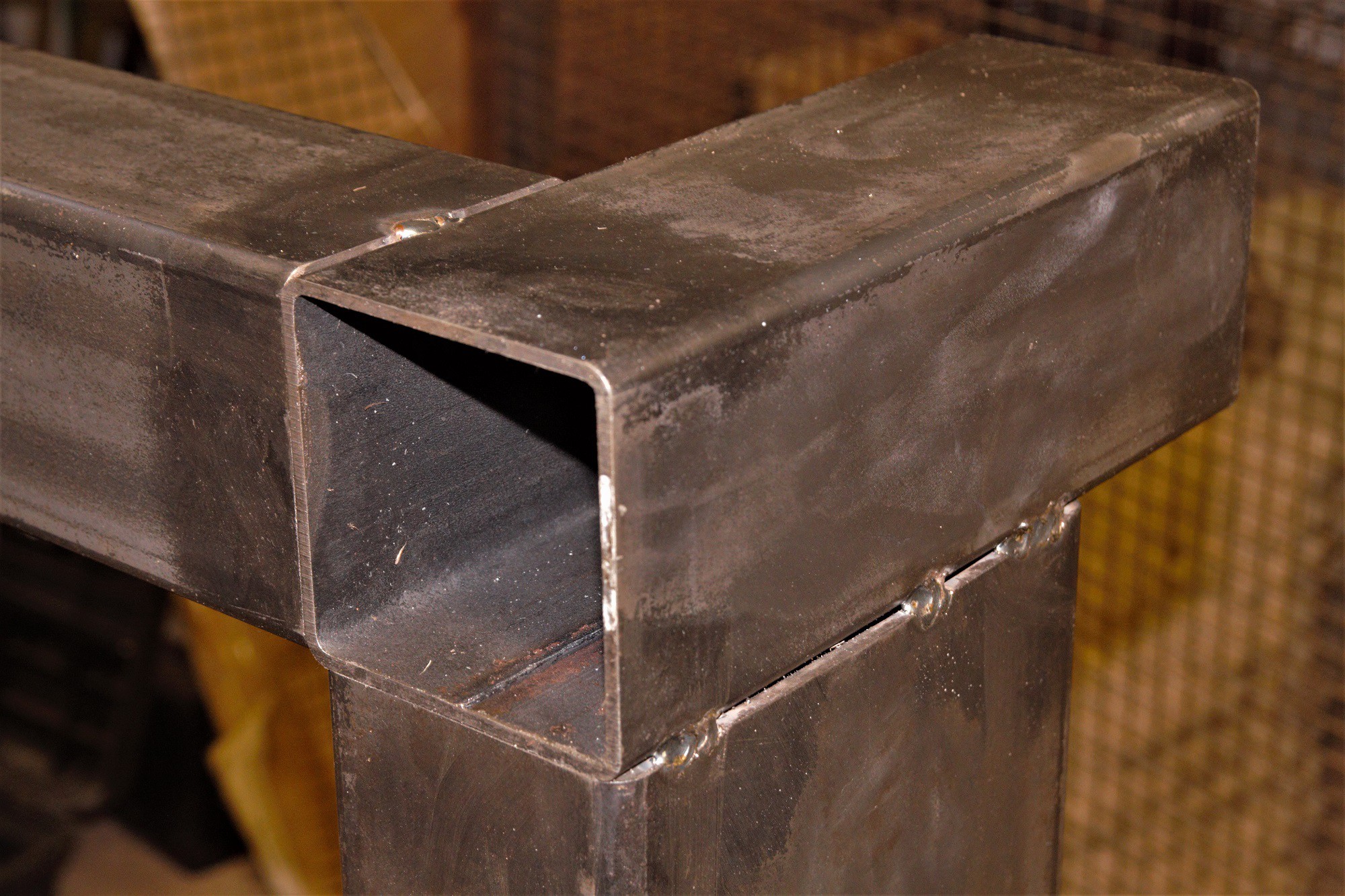
The sections are checked for squareness to each other and carefully tacked together in diagonal sequences to avoid distortion.
At this stage the construction seems to be wildly heavy and very much over engineered, but in the later stages the plasma cutter is going to be used to remove as much mass from the structure as possible.
2
Buidling the Swivelling Front Axle
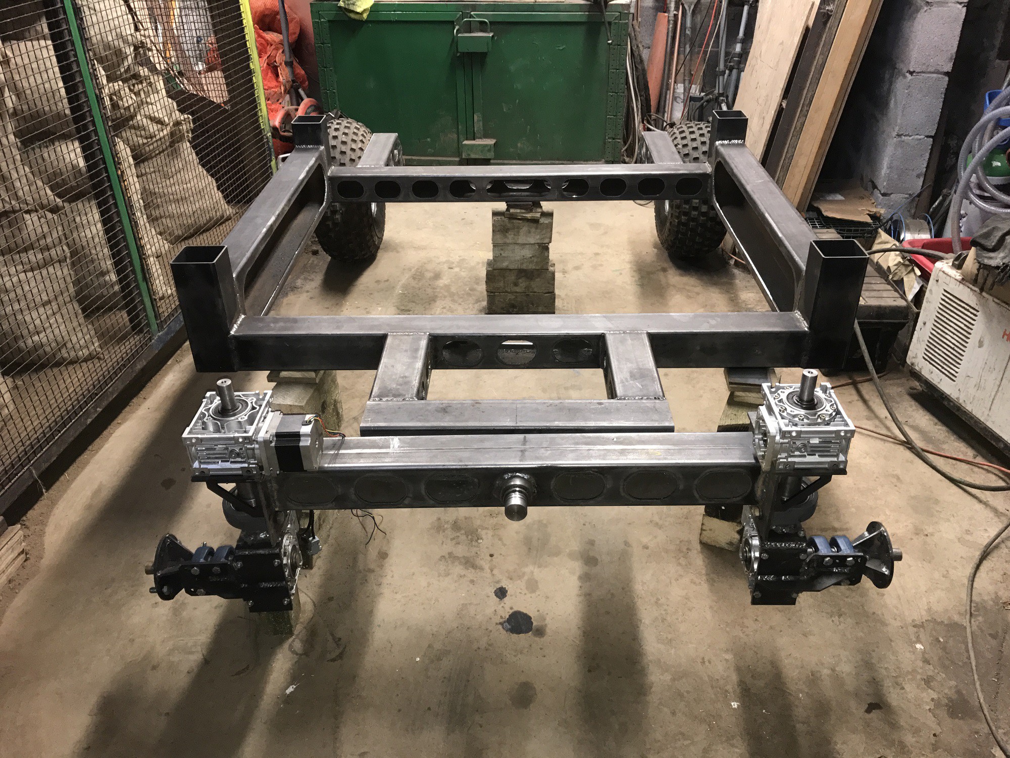
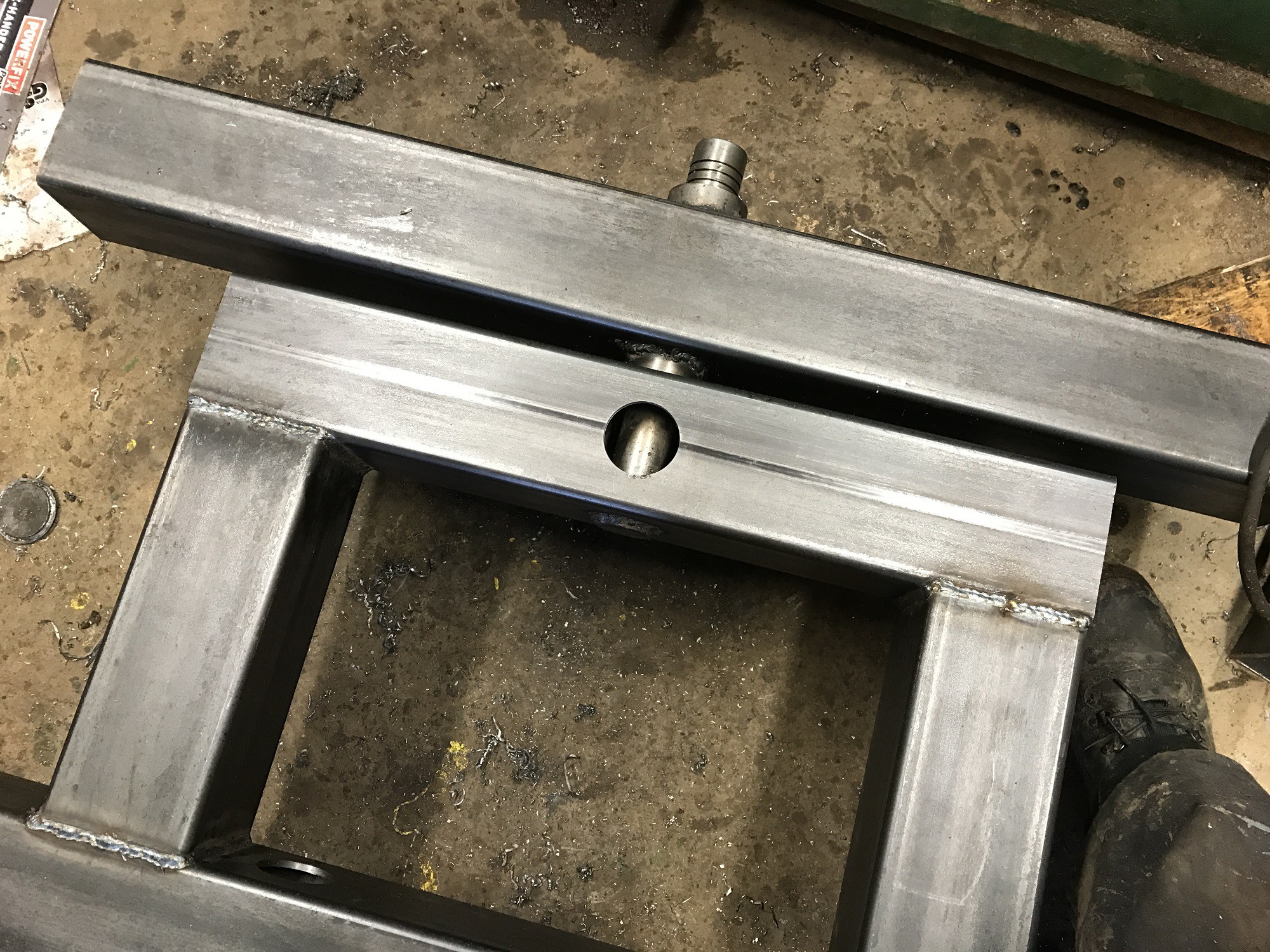
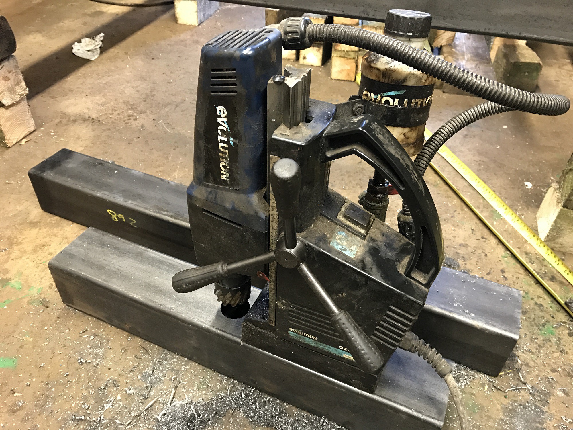
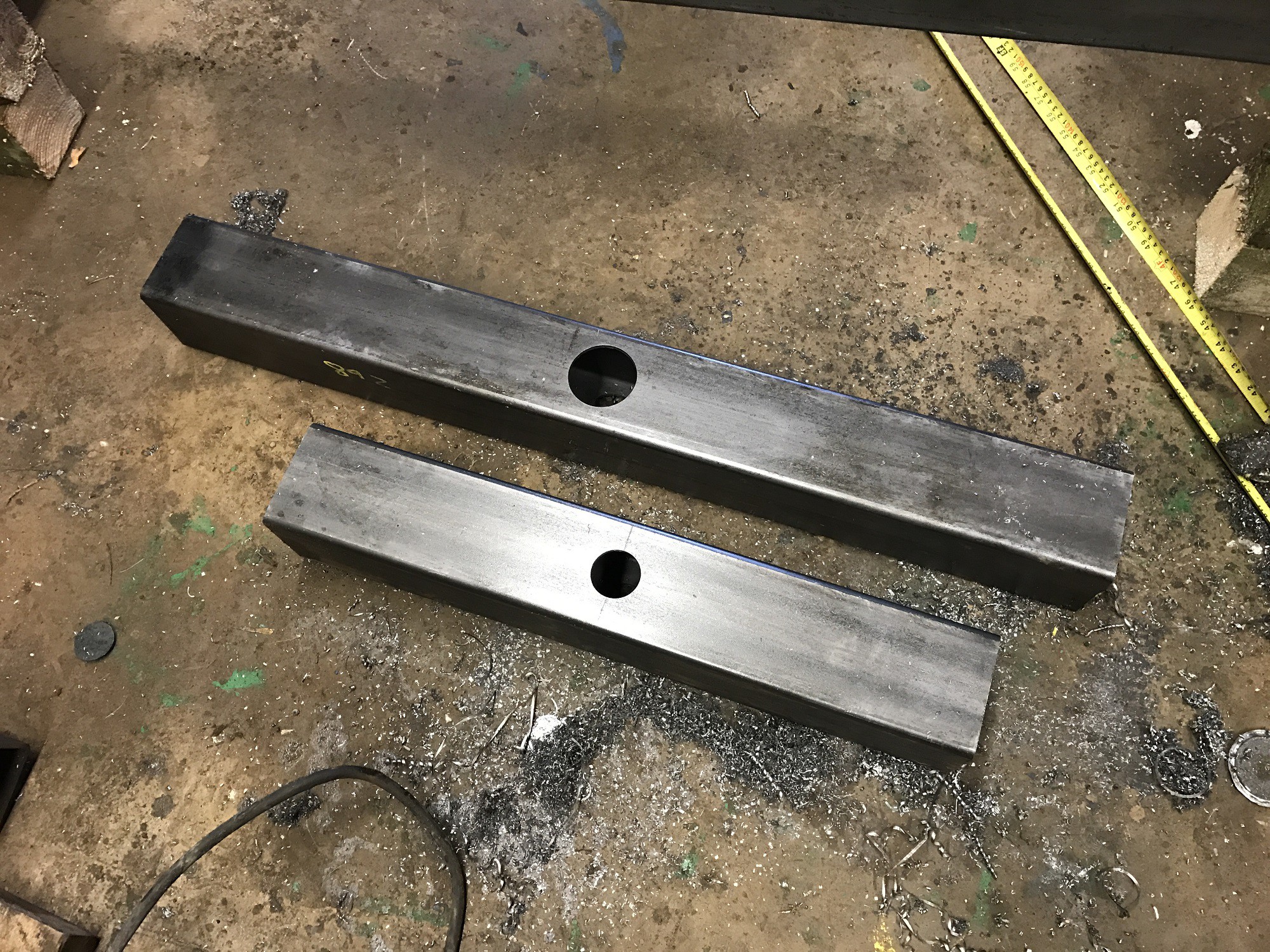
The front drive units are positioned relative to the main chassis and wooden blocks are used to level it up. This enables the front axle to be measured. It is then drilled each side with a diameter 60mm hole in it's centre using a broaching drill. The 600 mm long box is drilled diameter 40mm.
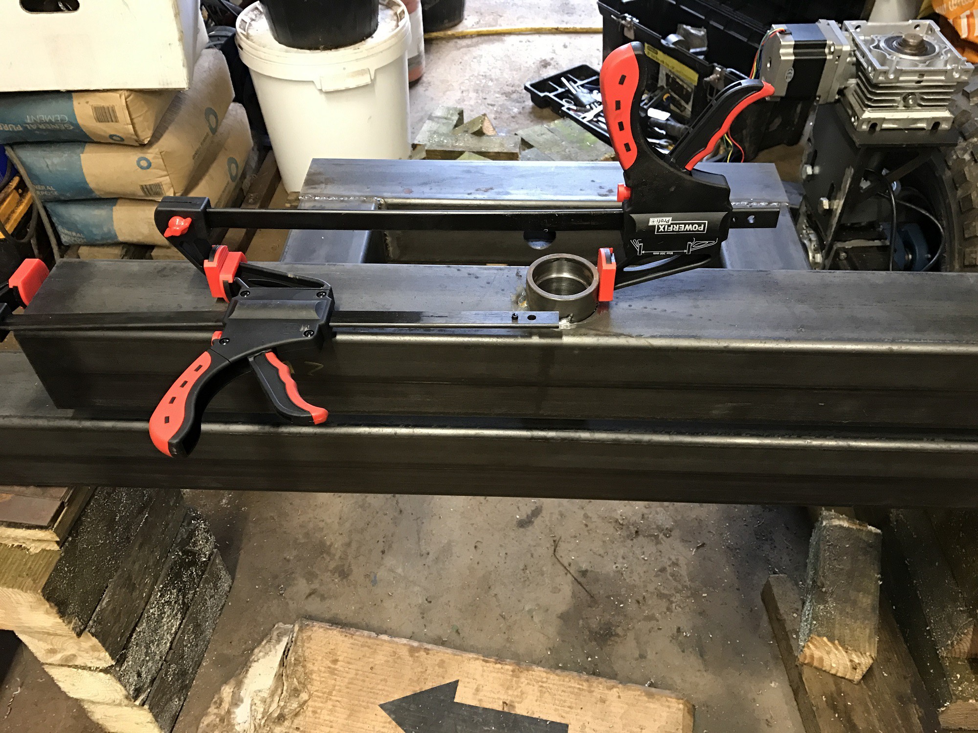
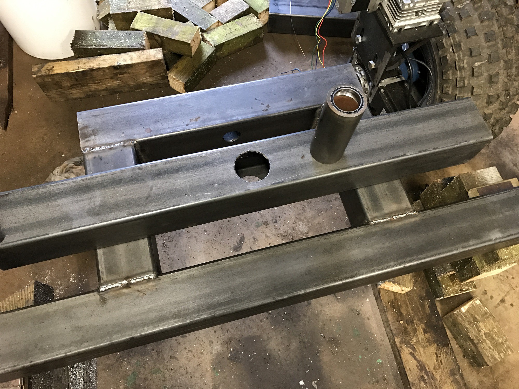
The small 100 x 100 box sub frame is welded onto the main chassis, getting it as level and square as possible and the suspension tube is inserted and welded into the 60 mm holes.
The low profile 50 mm bearings are inserted into the tube and the shaft is carefully positioned and welded in.
The 970mm axle box section is then welded to each of the drive units in turn.
3
Building the Back Axle Assembly
The back axle is a temporary fixture to enable testing of the main front drive units. The dimensions of the 100 x 100 mm box sections used are given by setting the rest of the chassis level and making measurements.
4
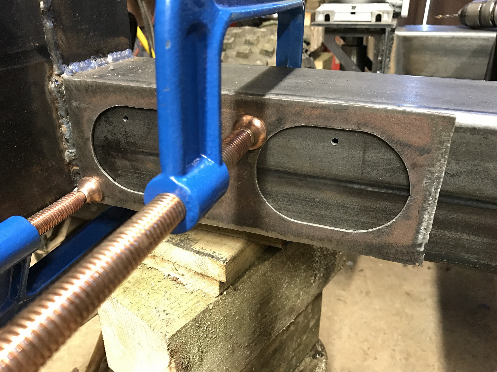
Making Oval Slots in 100 X 100 Box
The box sections used in the chassis are far too heavy and so weight needs to be removed using the plasma cutter.
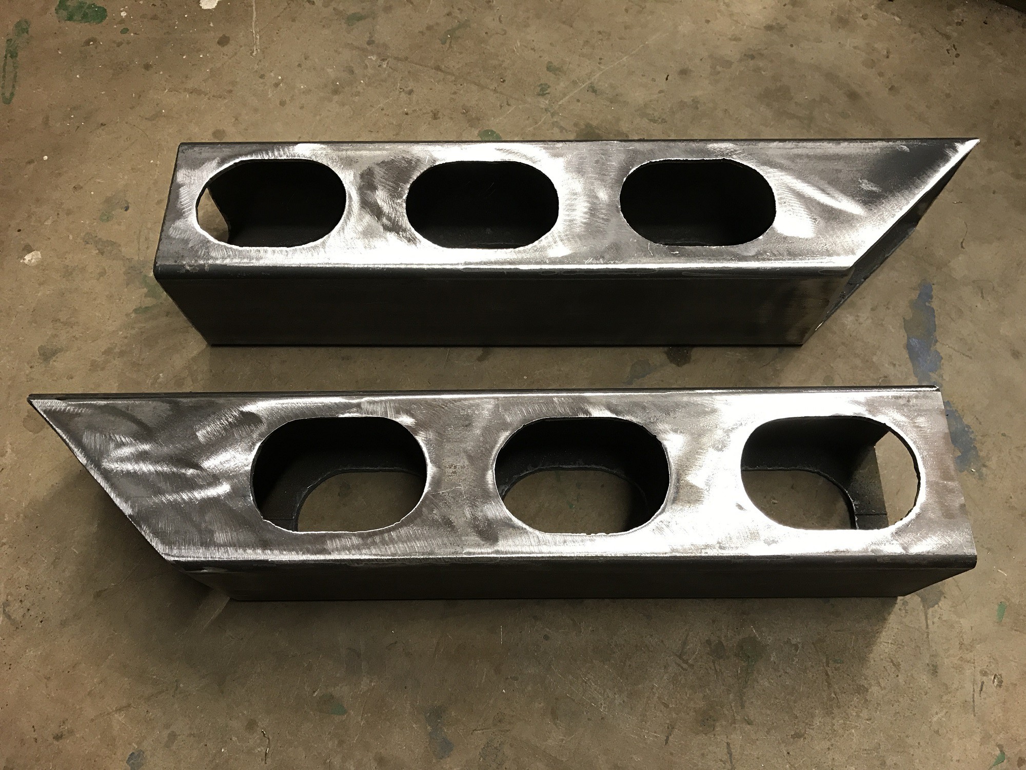
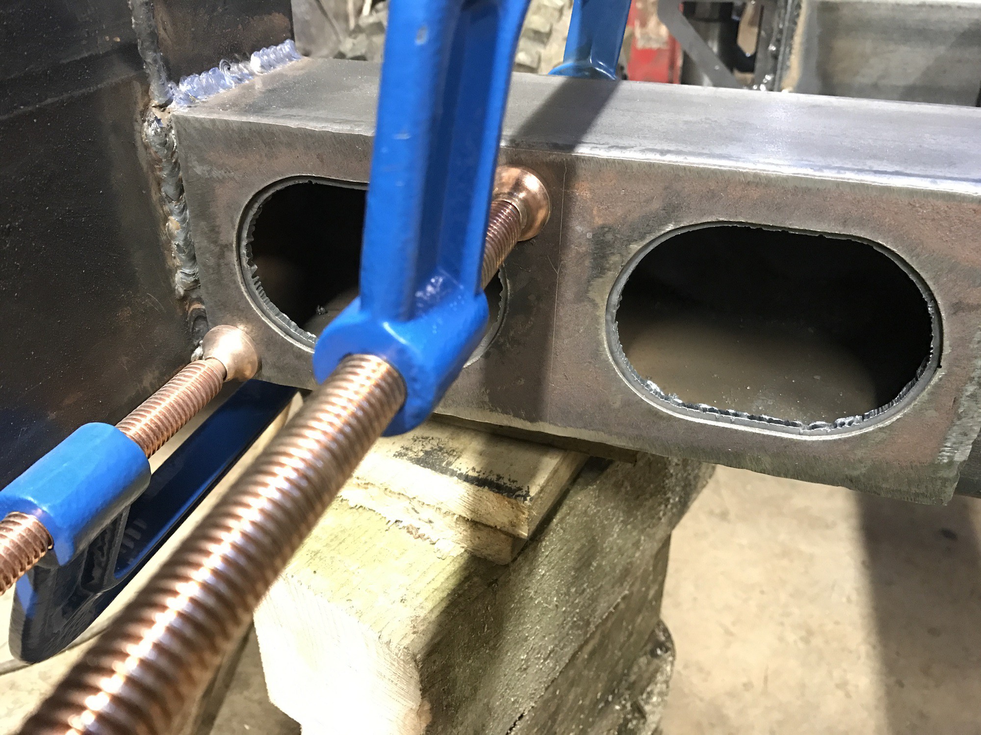
A template is made in 2mm steel and clamped to the box section wherever a hole is required. Before cutting begins, a small hole is drilled into the bit of steel to be removed which allows the cutting 'flame' to be initiated without having to blast through solid steel, which will very quickly destroy the nozzle. The plasma flame works much better by cutting sideways into steel.
A lot of practice is needed to get a clean cut, which starts at the drilled hole. The torch is held very firmly and is slowly dragged backwards against the side of the template. Never push the torch forwards or sideways! Sometimes the template has to be repaired with a file to ensure a smooth surface.
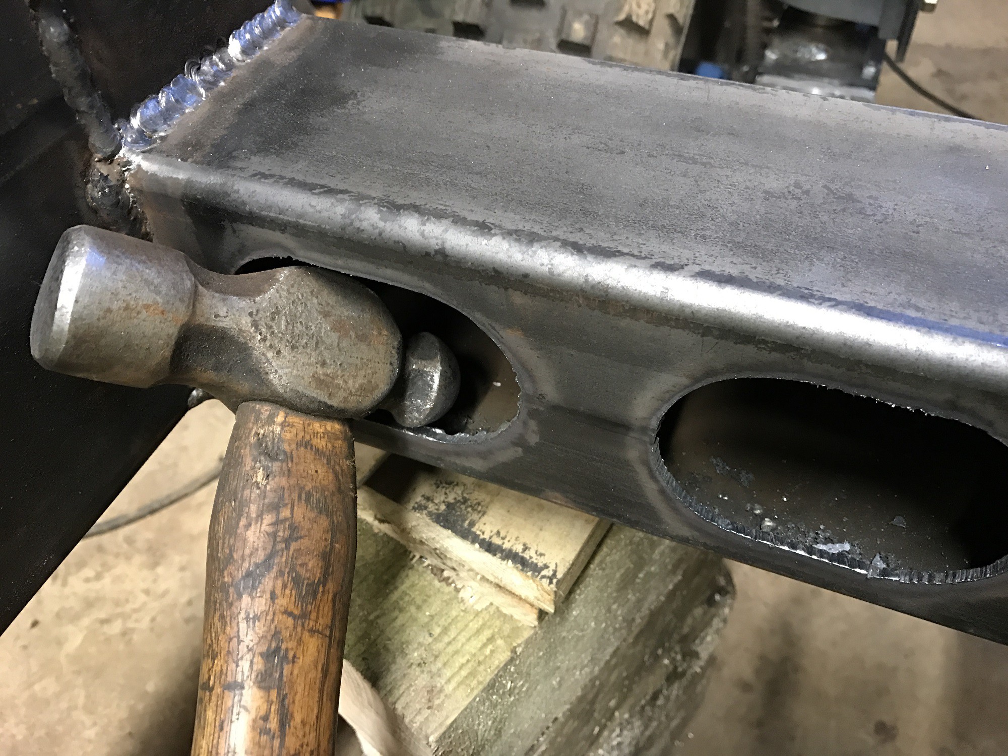
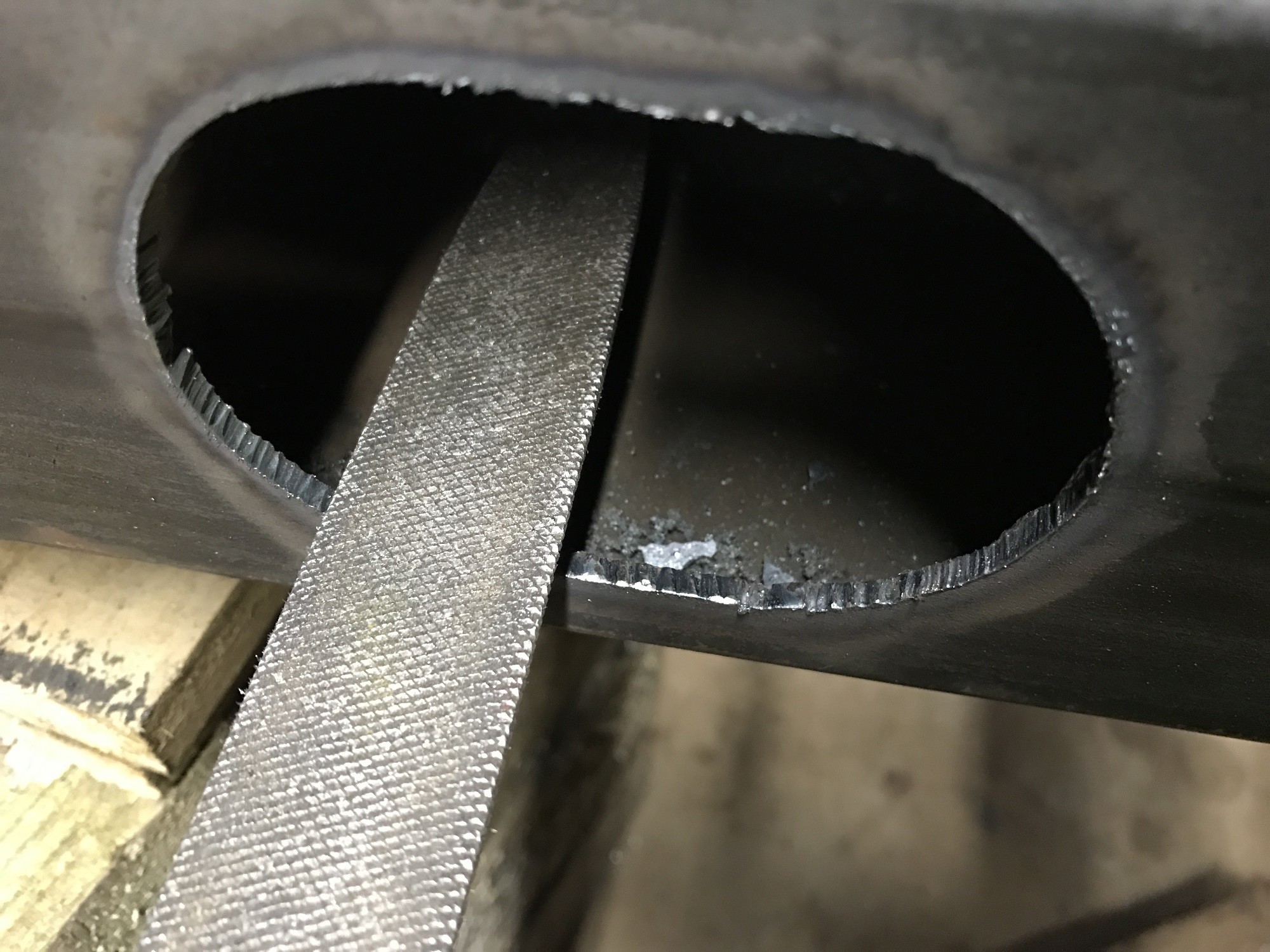
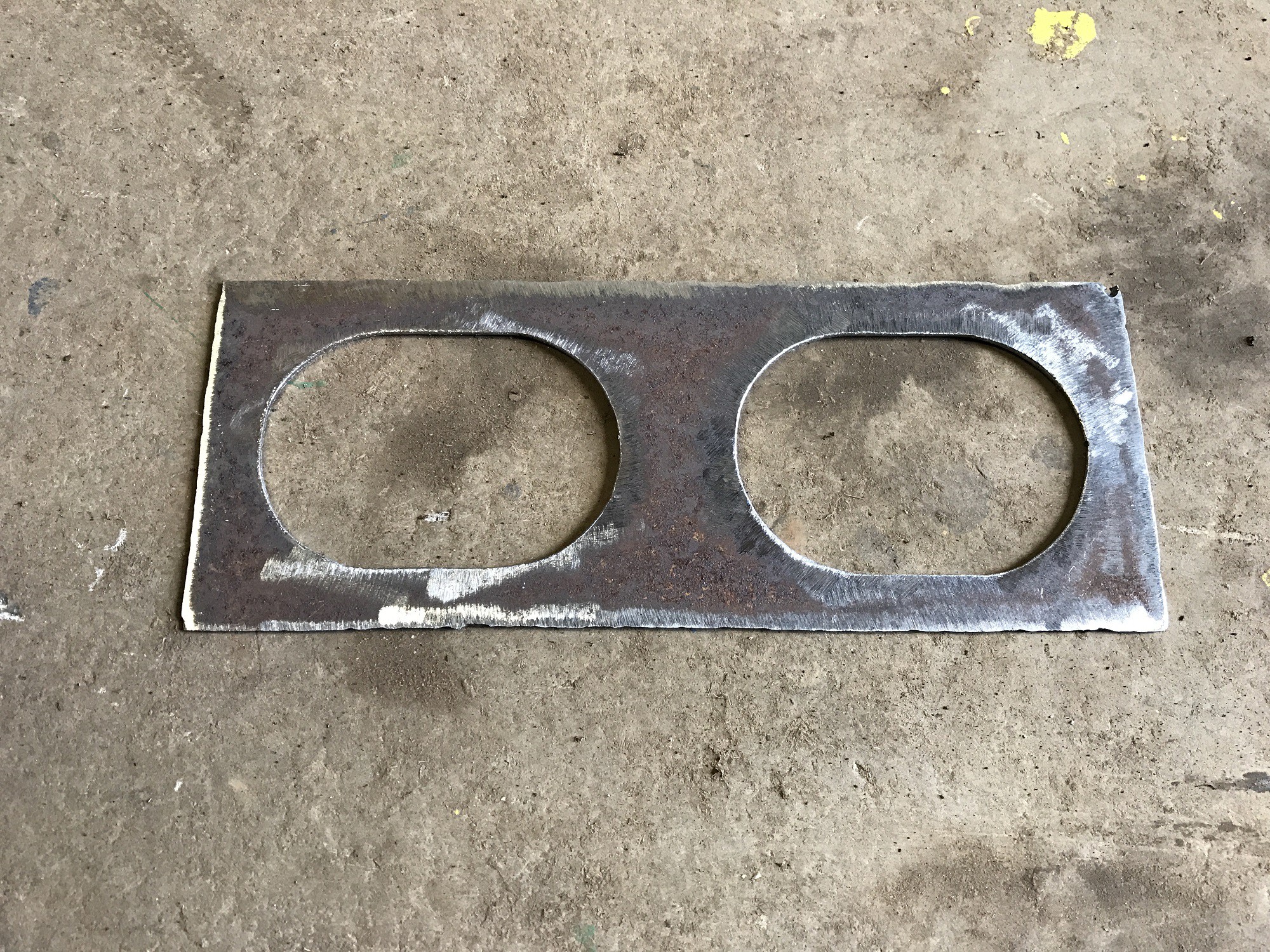
If done well, with a nozzle in good condition, the metal to be removed should just fall out and all the lines should be nice and clean, otherwise there will be a lot of very tedious work required to clean it all up. The slag created is simply knocked off with a hammer and the final surface filed with a coarse half round file. No grinding should be necessary!
5
Slotting Out the 200 X 100 Box
The 200 x 100 box is incredibly heavy, but is needed for ease of fabrication on the surface plate. It's much easier to remove the unnecessary material with the plasma cutter than try and build up complicated structures. Eventually we end up with a frame that has an attractive 'aerospace' design.
Rather than create a template I used some large washers that were about the right size. It's very satisfying to remove the large 'tongue' of steel with nice clean cuts although by this time the plasma nozzle was beginning to deteriate.
By the time I had finished that day I'd managed to remove 17 kg of material.
6
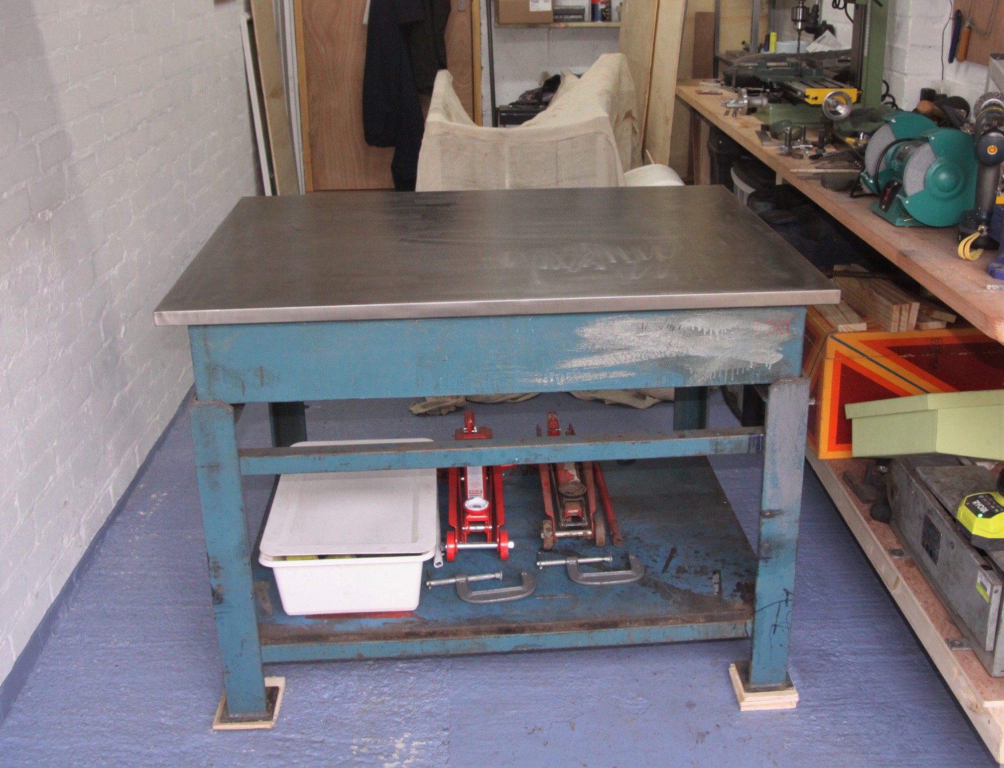
Finished Chassis
The chassis is finished and the drive / steering mechanism can be tested.
The chassis sides have the massive slot as shown in the photo above and this is for the CNC Y axis to run inside, so increasing the effective travel of the Y axis by 100 mm.
7
Steering and Drive Modules
The WEEDINATOR was originally designed to have 4 wheel drive with steering on each wheel for ultra tight steering turns and the ability to swivel around on it's centre Z axis. In reality, financial constraints have meant that only 2 wheels are driven and steered and the others are fixed.
Photo above shows wheel attach bracket being manipulated into shape with some stilsons. If I had oxyacetylene I would have heated the joints first, but bending cold like this works really well.
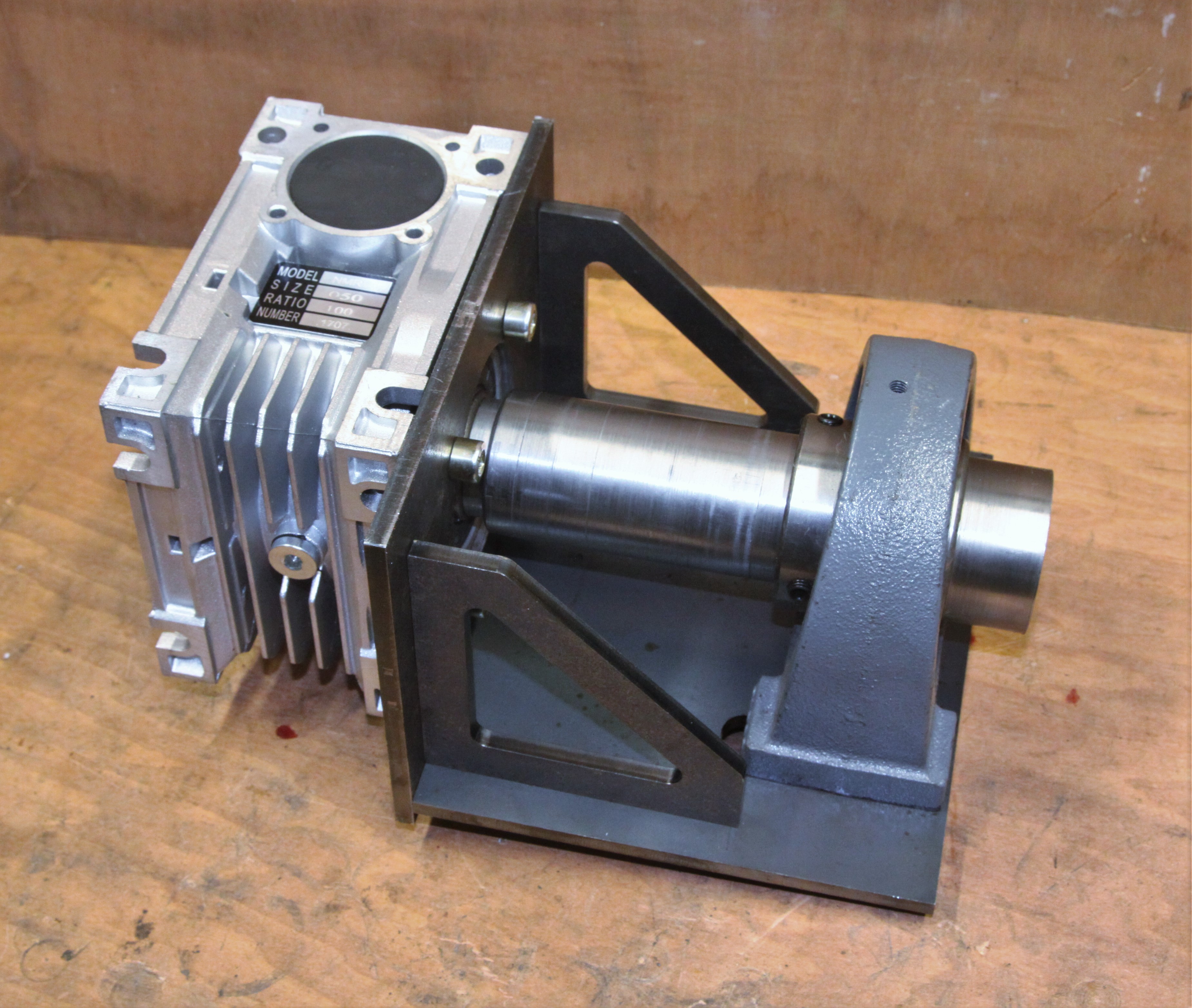
Above is the steering shaft, bearing and gussets being assembled.
.
After manipulation with the stilsons we end up with this assembly - ready to be welded. Again - this worked incredibly well!
Above shows the 2 sub assemblies joined together to create the whole steering / drive mechanism with the two 100:1 gearboxes.
The sketch below shows the main parts for building the CNC mechanism. The whole set of drawings are bundled in 3 zip files. X axis is HERE, Y and Z axis's are HERE. Claw mechanism (R axis) is HERE.
Parts:
X axis saddle box section, 4mm x 100 x 200 x 2 of.
The weeding mechanism is basically a rotating claw mounted on a CNC machine. The machine never tries to target individual weeds - this would be a big mistake - instead it will prevent weeds from ever reaching the surface by disturbing the soil during weed germination, which kills them very effectively. We might want to do this twice a week at certain times during the season.
The GIF above shows how the mechanism will work.
Below is what the ball screw sets look like:
The collar and circlip at bottom of photo provide locking of ball screw into position in association with the chunky bearing block next to them. The nut also provides anti backlash. Photo above shows how the motors are mounted. The motor is positioned in the same plane as the ballscrew and bolted onto the horizontal plate with large laser cut circle cut into it.
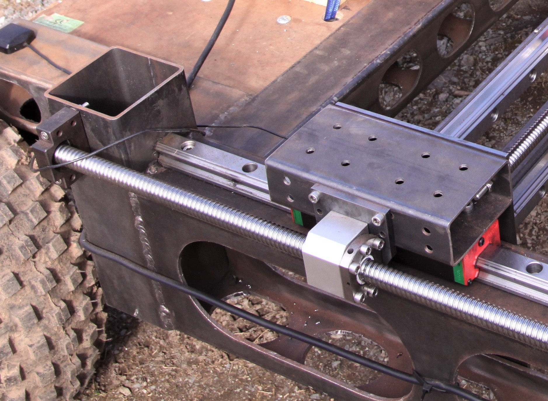
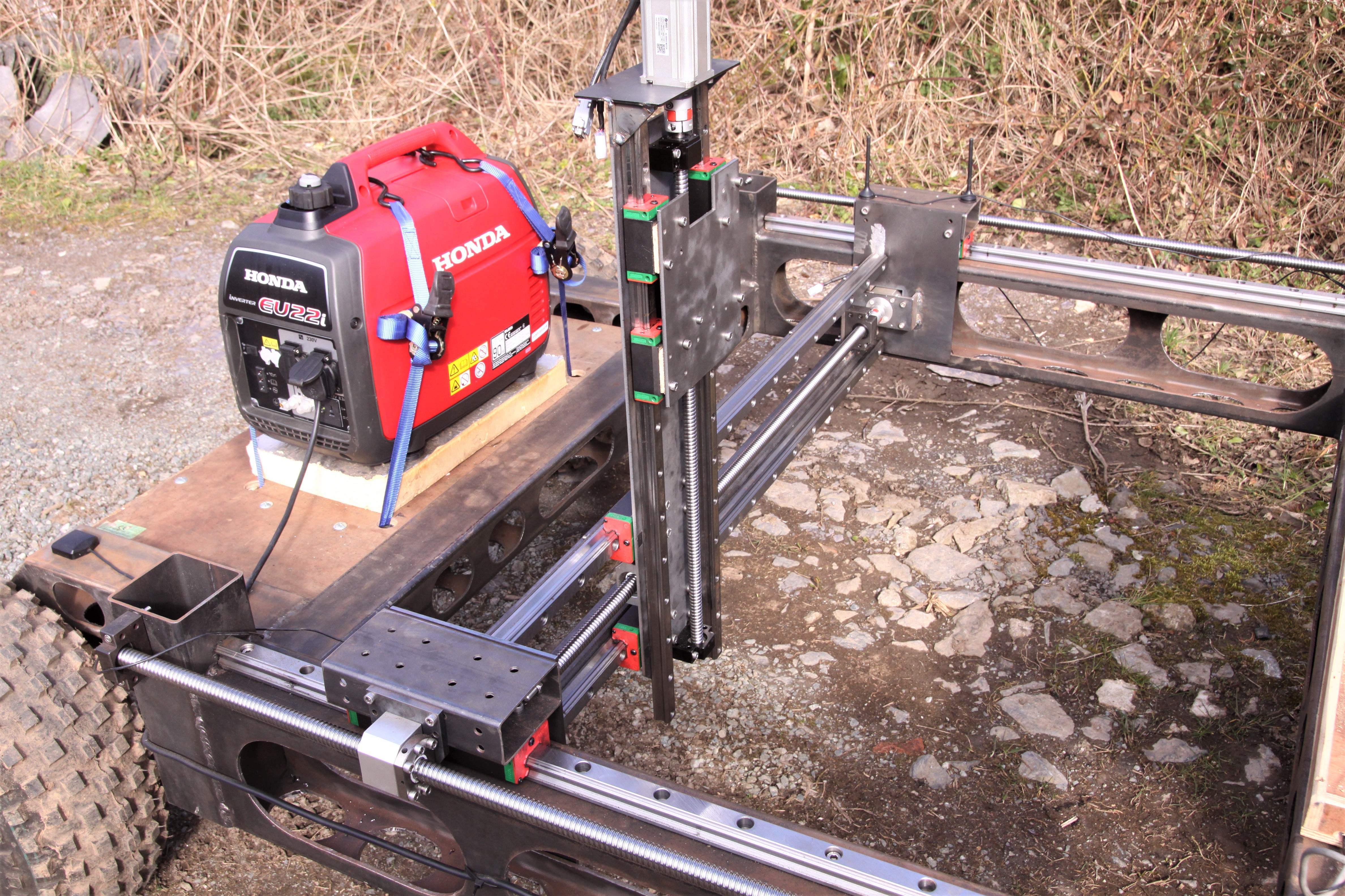
Above shows the X axis 'saddle' running on heavy duty hardened steel HIWIN rails from Fasttobuy. The key component is the 100 x 50 box which is peppered with drill holes to allow the Y axis plates to be bolted on providing attachment to the ball screw nut. The guide sets comprise the rail and two 'blocks' or 'runners':
Above is the Y and Z axes attached to the X axis. Firstly, the Y axis is attached onto 2 lengths of 50 x 50 x 3 angle, which need to be cut to length. Do not weld them on at this stage!
The best way to do this was to completely assemble the Y and Z and then offer up the whole assemble, including the 50 x 50 x 3 angles, to the saddles. Although rather awkward, this worked really well and ensured that the Y axis components were parallel with themselves and contiguous with the X axis.
Next, a hole was cut with plasma cutter using the laser cut template included in the laser cut zip file below:
The hole is square for the 400 W motor to protrude through. The ground patch above the rail in the photo is where I incorrectly positioned the assembly and had to remove it again. The lower 50 x 50 angle needs to go as low as possible on the vertical saddle plates to get the motor running in the middle of the 200 x 100 box section slot.
 GOAT INDUSTRIES
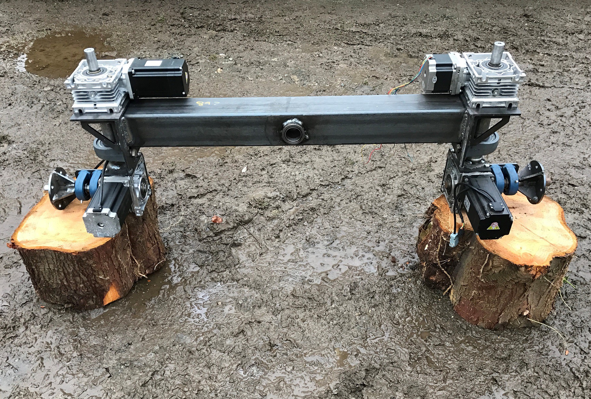
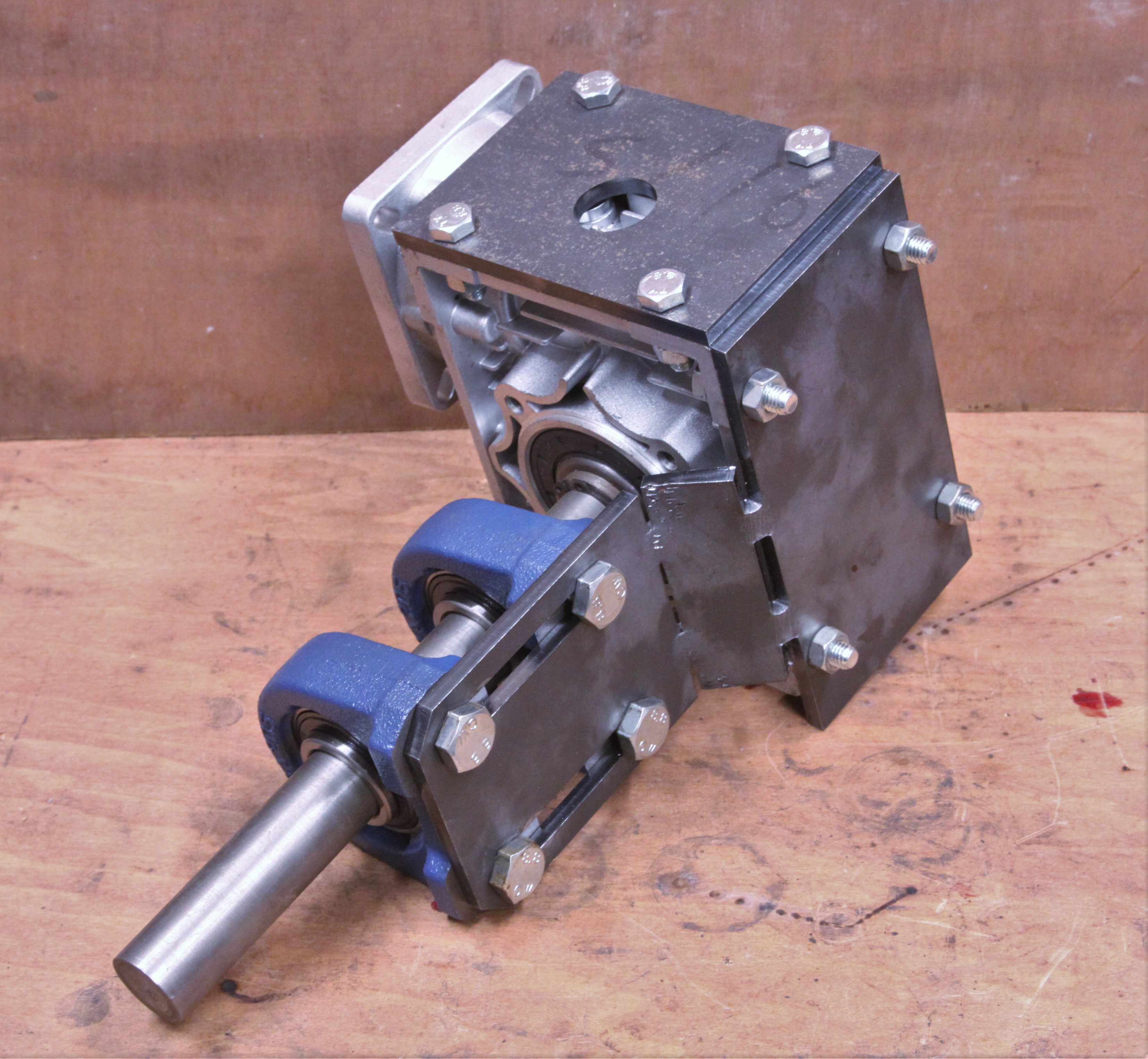
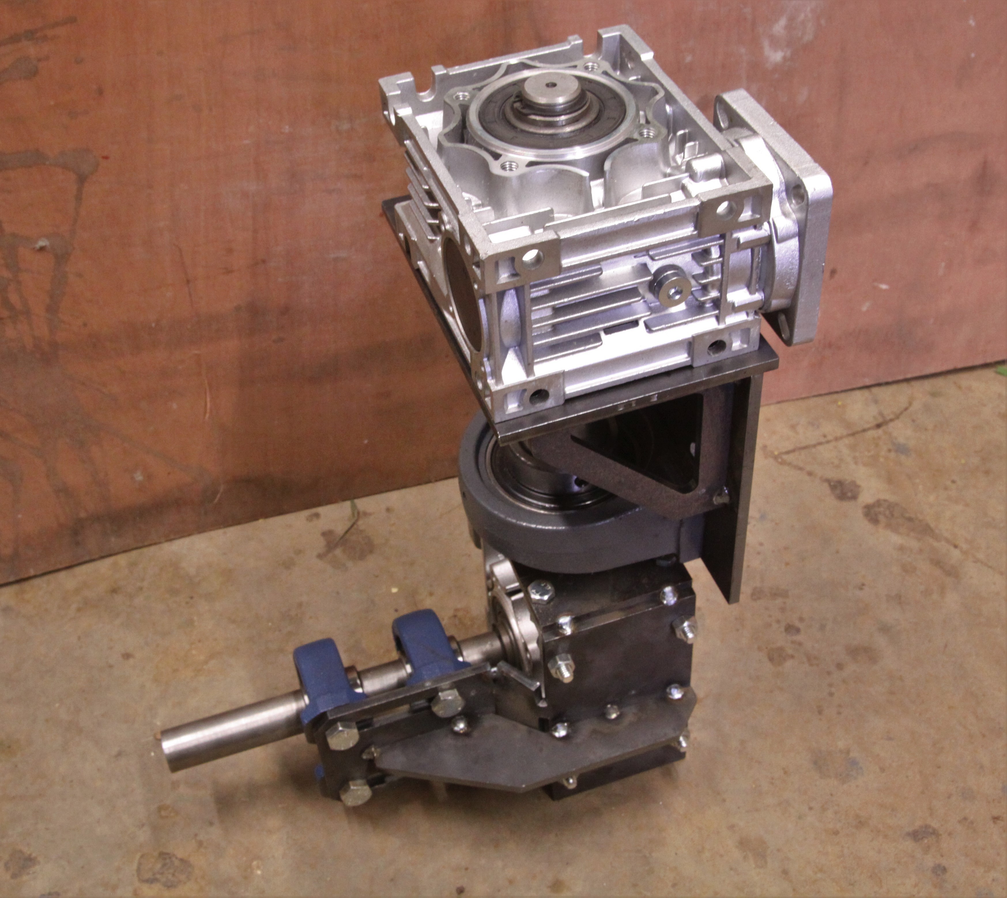 Above shows the 2 sub assemblies joined together to create the whole steering / drive mechanism with the two 100:1 gearboxes.
 Parts:
 The GIF above shows how the mechanism will work.
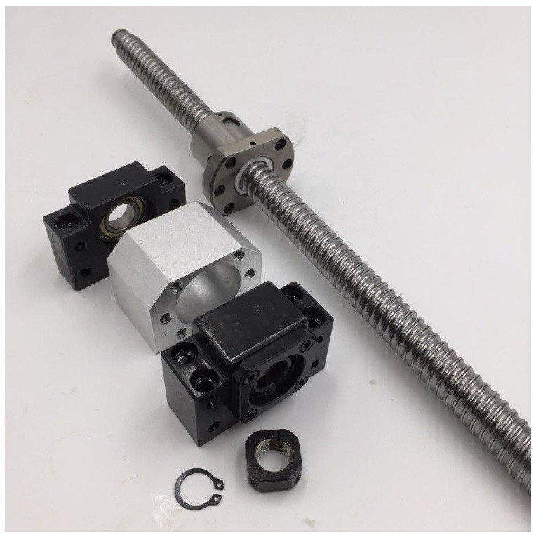 The collar and circlip at bottom of photo provide locking of ball screw into position in association with the chunky bearing block next to them. The nut also provides anti backlash.
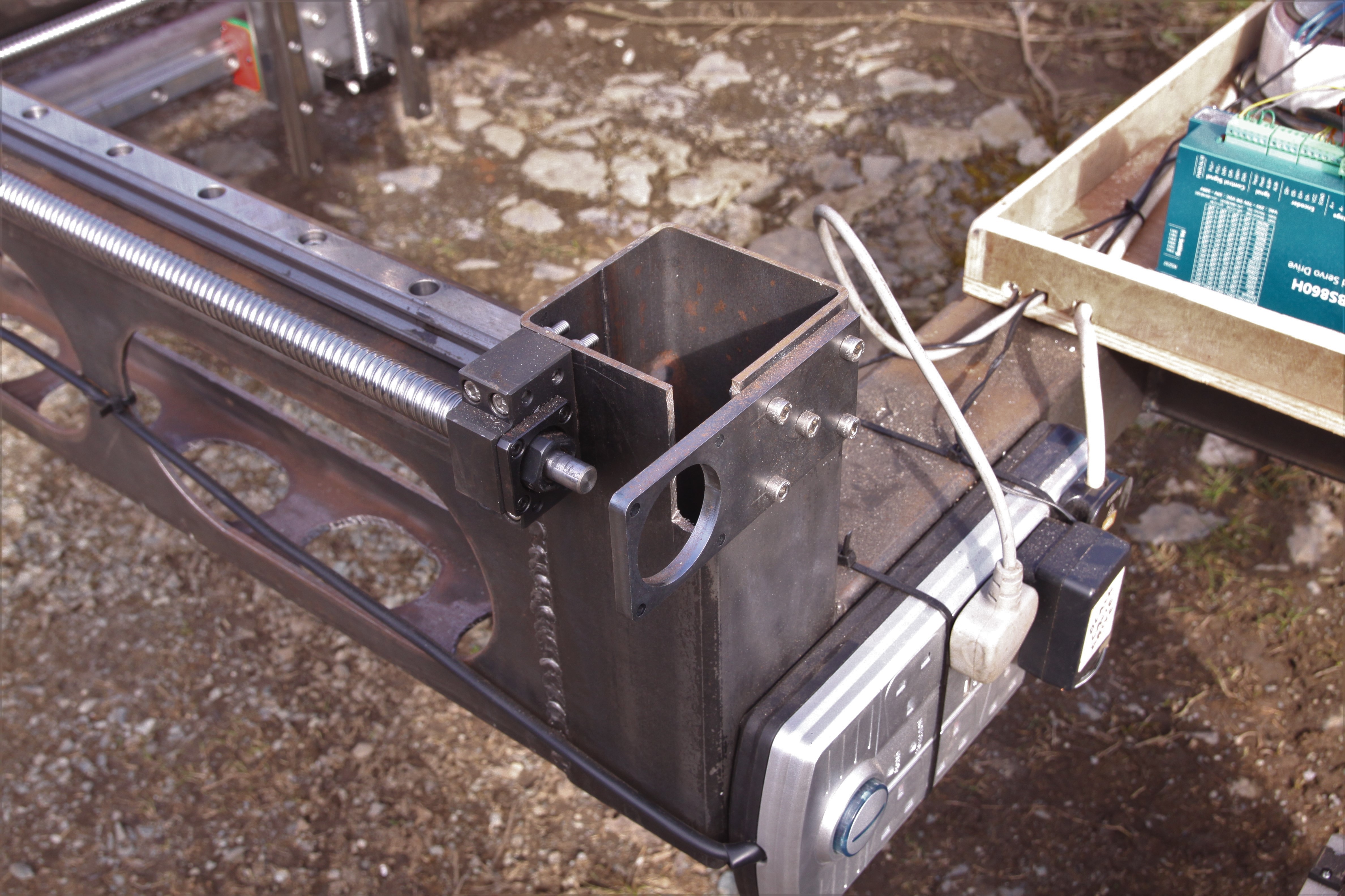
 Above is the Y and Z axes attached to the X axis. Firstly, the Y axis is attached onto 2 lengths of 50 x 50 x 3 angle, which need to be cut to length. Do not weld them on at this stage!
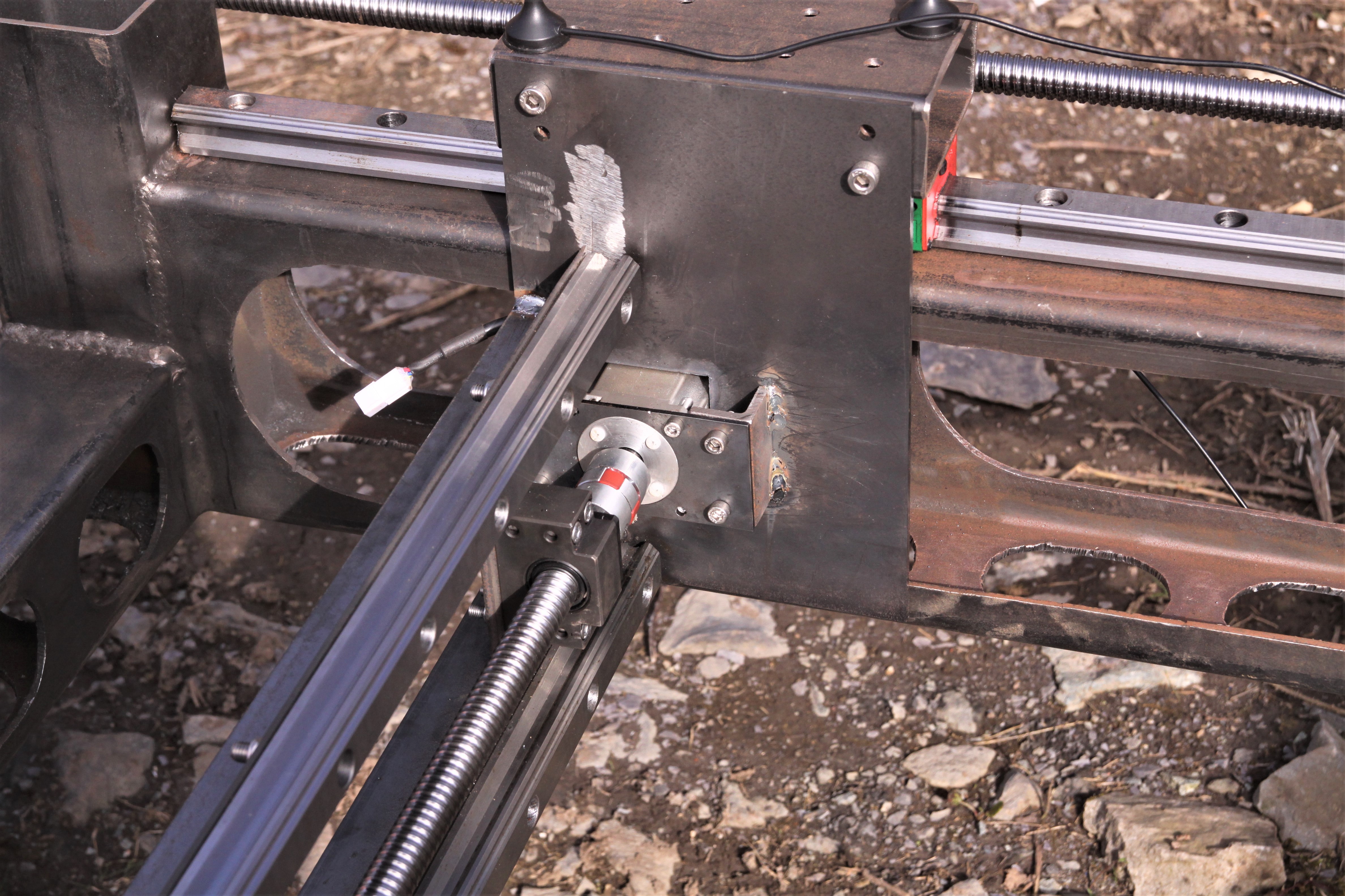 The hole is square for the 400 W motor to protrude through. The ground patch above the rail in the photo is where I incorrectly positioned the assembly and had to remove it again. The lower 50 x 50 angle needs to go as low as possible on the vertical saddle plates to get the motor running in the middle of the 200 x 100 box section slot.
Discussions
Become a Hackaday.io Member
Create an account to leave a comment. Already have an account? Log In.