Close
0%
0%

EMDrive/satellite

Developing a small fuelless microwave thruster

Similar projects worth following
The EMdrive is a new type of thruster - recently invented by Roger Shawyer & Guido Fetta.
Unlike other propulsion systems which need to repel mass to produce thrust, the EMdrive can convert electrical energy into thrust directly.

There are endless uses for an EMDrive - in terrestric and in space applications.

A working EMdrive would start a revolution in spaceflight, enabling manned deep space exploration.

Several builds have been made worldwide (eg Chinese University, NASA), many show positive results. This topic is still quite new and needs a lot of research.

Most EMdrive builds work with frequencies around 2.4 GHz because a high power RF source for them can be made out of a microwave oven magnetron.
My attempt is is to build one which works with 24GHz, which reduces the form factor significantly and makes it possible to be used in small satellites.
A so small EMdrive could be flown to space for 20000$ on a pocketqube satellite.

OVERVIEW

-------------------------------------------------------------------------------------------

The EMdrive is derived from a closed cylindrical microwave waveguide. The main difference is that one end is larger than the other. When RF is fed into the cavity and a resonance is achieved - according to Shawyer a thrust force will occur.

---

The first builds have not been summarized due to documentation cleanup process

---

EMDrive V3

===============================================

The V3 is a silver cavity build, fed by a fully controllable RF source capable of beeing tuned between 22 and 26 GHz.

The reflected power can be measured in amplitude and phase.

First measurements with acoustic vibrations (by OOK modulation of the RF source) show a force near the designed target resonance frequency. The last experiment is reproducible and shows clear signals. Further tests must be performed to check for directivity of the force.

PS: Many many thanx to all the people who gave us very helpful hints how to improve the system. It has been an exciting ride for us until now, and we hope to provide a functional Baby-EMdrive soon

Special thanx go to TheTravellerEMD, Marvin Macportain, Keegan Reilly, Aurelio Chargb Ramos

EMDrive V4

===============================================
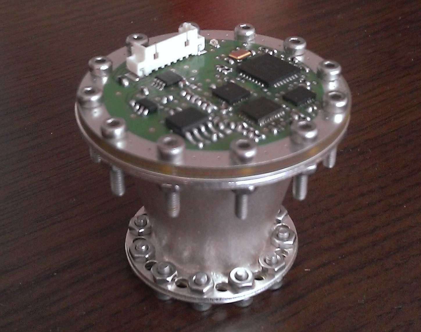
This build was a complete integrated version which has been tested at the TU Dresden with Prof. Tajmar.
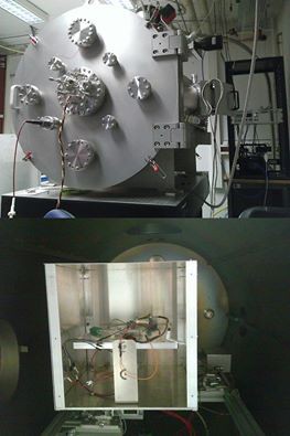
It should have been the flight version for our satellite in case the test would heve been more successful.

We had thermal issues during testing, with temperatures of the amplifier rising up to 90°C.

This led to a massive power derating in the amp.

We had to reduce power to keep the temperature low, so the final force was only slightly above the scale´s resolution.

Other effect like lorentz forces and thermal deformation had a significant pattern in the measure plot.
Tests have been made for 0°, 180° and 90°
Results are not for publilcation yet - we will perform further tests with version 5.

EMDrive V5

===============================================

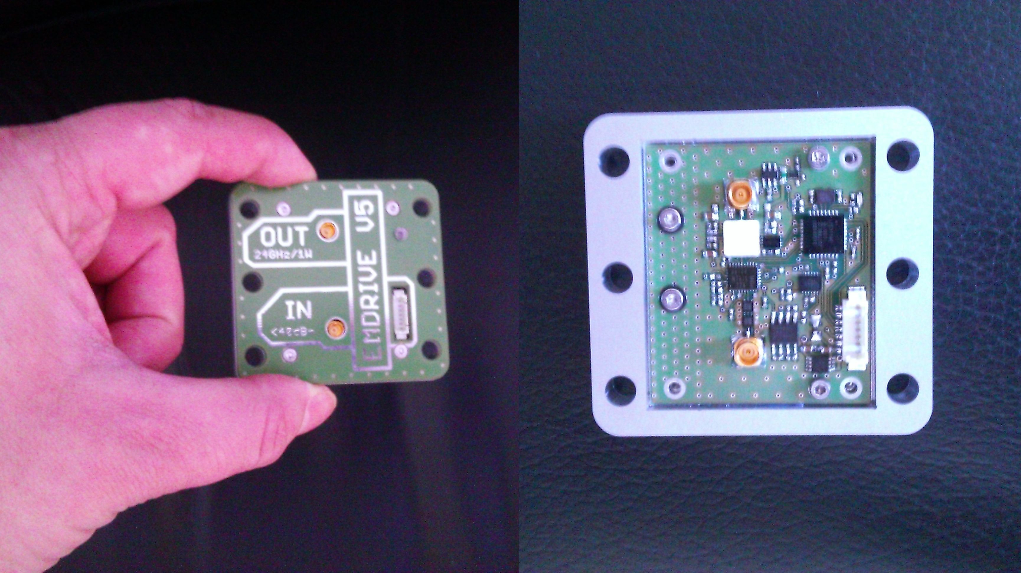
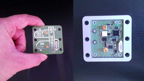
This is a development unit - derived from the V4 - which is intended to be tested at TU Dresden. It has some improvements to solve the problems that we had during testing of the V4.

It has an amplifier with better efficiency and is well thermally coupled to the casing for better heat management.

The new silver cavity geometry has an improved shape based on a proposal in Shawyer´s actual patent paper.

This shape will ensure that the pathlengths of the reflected waves on the longitudinal axis of the cavity is always kept to a multiple of lambda/2 of the resonance frequency.
  • New kind of thruster in development

    Paul Kocyla07/19/2017 at 20:34 1 comment

    Just a quick update after a long time:

    The Dresden University will probably continue measurements on the BabyEMDrive thruster with an improved torsion scale. It can resolve 20nN.

    Please check out another promising technology for propellantless propulsion. I decided to share the development and tests on a Mach Effect Thruster:

    https://hackaday.io/project/26013-mach-effect-thruster-xperiments

  • Tests

    Paul Kocyla03/23/2017 at 21:20 1 comment

    In February the EMDrive V6 has been under test on the Technical University Dresden.

    As the pretest-board didn´t output the expected power, I made a quick redesign right before the test date.
    The output after a day in vacuum was around 500mW, that´s "only" 3dB less than the desired 1000mW. Not so bad for a simple 4-Layer board.
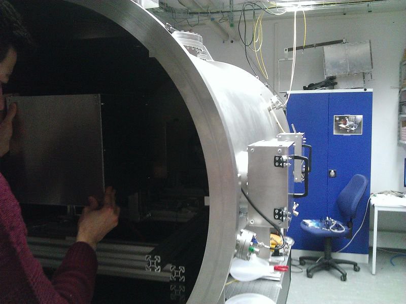
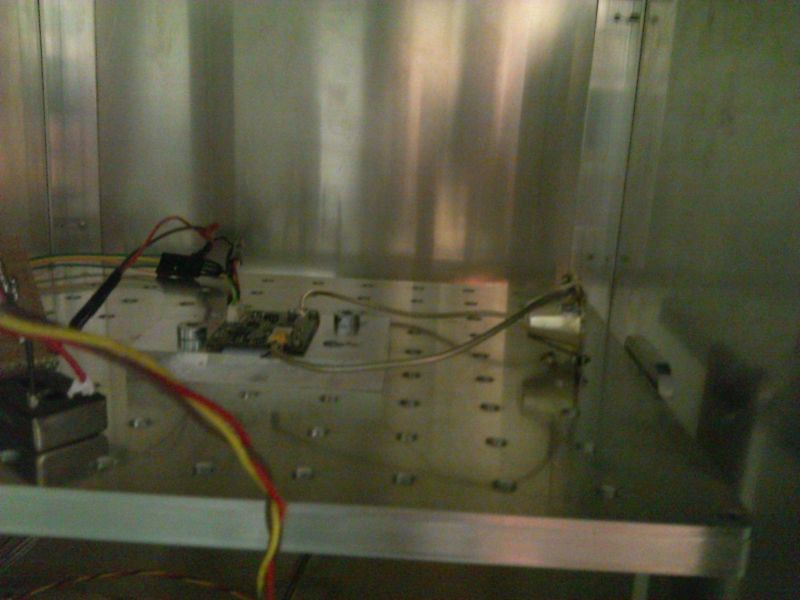
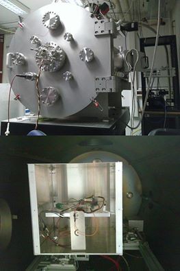
    Here is the board inside the scale box:
    I am not allowed to publish detailed results, but some information upfront:

    The thermal drift was much bigger than the possible thrust - anyway the force is depending on the frequency and seems - I say seems because that´ s only a quick observation - to be proportional to the amplitude of the resonance peaks.
    I was only able to spend two days in Dresden so the following long duration tests has been made without my presence.
    Possible forces are lower than 0.1µN, it´s still not 100% to say without eliminating the thermal drift, so we have to wait until this problem is solved.
    The thermal drift shows always in the same direction and disturbs the interesting signal into uncertainty. So thrust is not confirmed but also not busted yet.
    From my side - the Baby EMDrive is completed, unless an affordable amplifier with a significantly higher power appears.
    There is an IAC abstract from Prof. Tajmar submitted about this EMDrive with details available on the conference beeing held in September this year in Australia.
    Thanx to the many interesting discussions and suggestions.
    Special thanx go to Prof. Tajmar, Matthias Koessling and Marcel Weikert for making the measurements possible, and Dave, who boosted the project by financial help - hope we get some thrust out of it so we can send it to space.

  • Pre-Test smulations

    Paul Kocyla02/05/2017 at 16:18 1 comment

    Jamie (monomorphic) ran a simulation on the new EMDrive V5 cavity model. Great work and many thanx!
    He detected two modes - would correspond with my two resonance peaks on the real thing.

    Kein automatischer Alternativtext verfügbar.

    Kein automatischer Alternativtext verfügbar.

  • New board ready for testing

    Paul Kocyla02/02/2017 at 22:42 3 comments

    The last board showed some power leak. The expected power could not be reached. It even degraded to 40mW - bad. Now I made a new board with better connectors and more careful routing which is ready for testing in Dresden.

    It is prepared for the highly sensitive scale and can deliver more than 200mW with 24GHz at 85°C (after cable- and connector lossed), so we should not get thermal issues this time. The ALU-Plate will be also fixed to the scale for better heat dissipation.The cavity is new (blogged about it before). It shows two clean resonance peaks at which we will test for thrust.
    Sweeps will also be made in case there are some other phenomena which may occur beside the two resonance frequencies.
    For an eventual integration into a satellite, the board can find and track the resonance peaks automatically.

    I´ll make a 360° video of the test preparation in Dresden (if allowed).

  • Measurement followup

    Paul Kocyla01/06/2017 at 06:07 1 comment

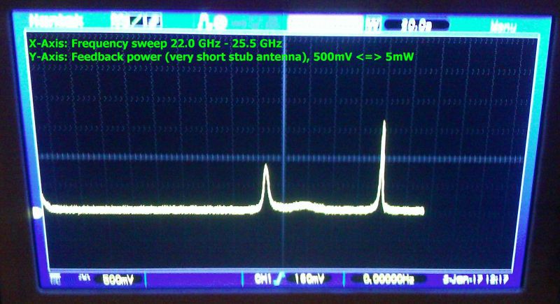
    Improvement in cavity resonance after simplifying the feed antenna:

    In the previous measurements I soldered a stub to the feed connector to reach lambda/4.
    In this configuration, this stub is missing. The feed pin is shorter than lambda/4 and its angle is the angle of the cone wall.
    There are only two peaks now, the first was also visible before, the second has a more narrow bandwidth and higher amplitude.

    Probably these peaks represent two different cavity excitement modes in this frequency range.

    We will track both of them in the next test session.

  • Cavity V5 measurements

    Paul Kocyla01/03/2017 at 21:19 5 comments

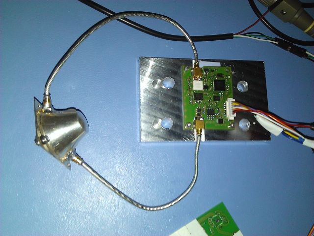
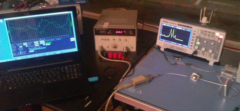
    Here is the setup:

    The EMDdrive V5 board is connected to the cavity´s feed antenna (lambda/4 stub).

    A shorted antenna is used as feedback port which is connected to a power sensor.

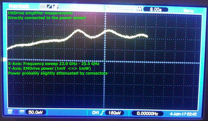
    First, I measured the amplifier´s performance by connecting it directly to the power sensor.
    Here are the results:

    At over 23.5 GHz the power is over 100mW - hmmmm it´s a 1000mW amplifier, so that´s not that good, the board is probably not perfectly designed, cables and connectors have losses. The sensor has a 20dB attenuator (compensated calculations for that) and a SMP to 2.92mm adapter, they will probably also cause some losses. So let´s say it´s around 150mW at the working frequency range.

    Now comes the interesting part: The feedback port is connected to the sensor, and frequency sweeps are performed. It´s basically a scalar network analysis.
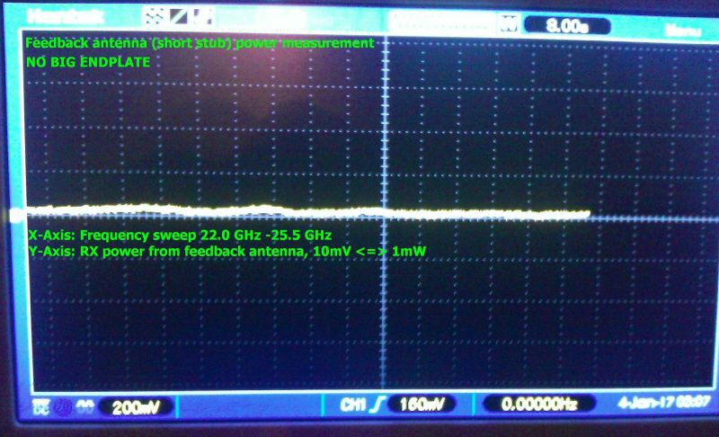
    First, I left the cavity opened - this means the big endplate was not connected.
    Here is the result - flat, almost no feedback. That´s not surprising, should be like this:

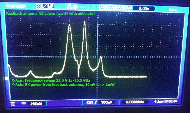
    Look what happens when the big endplate is attached:

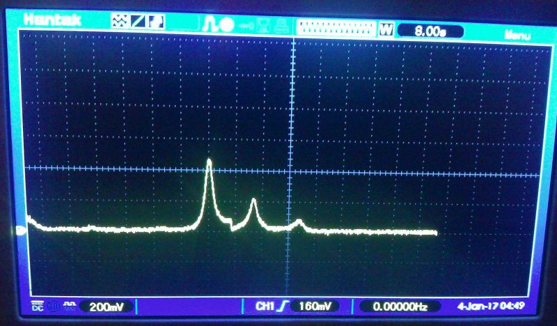
    We get three main peaks. Two strong and one weak - and some smaller artefacts.

    I assume the small disturbances are caused by the antennae destroying the optimal shape of the cavity.

    When you look at the power level, it seems that the feedback antenna is sucking all the power out off the cavity, not good, it was probably too long - but better starting off too long than too short. So I cut the feedback antenna shorter, from around 1.7 mm to 1mm (approximately). Here´s the result:

    That´s better. The feedback antenna now sucks 40mW instead of 100mW. That´s better, but still too much.

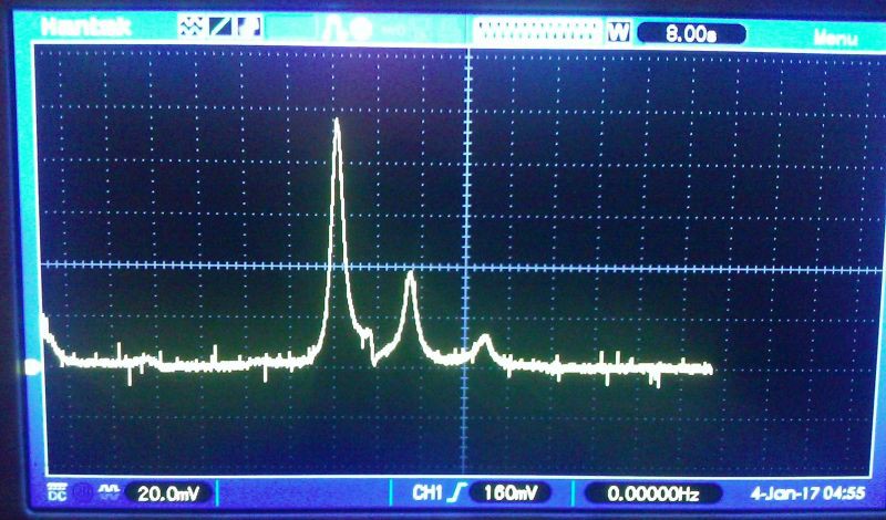
    Now I cut the antenna to the ground, it´s just a pin in the hole, but the result seems ok:

    Note that the V/div is now 20.0mV instead of 200mV, so it´s sucking just 10mW now.

    Probably some room for improvement here - let´s see, but that´s acceptable.

    BTW before the trolls cry again because of missing axis labels: The two last pictures have same labeling than the third last - I´m just too tired to insert them - have a newborn baby now and a full time job: X:FRQ sweep, Y: power 10mV <=> 1mW

  • EMDrive V5 and cavity prepared for testing

    Paul Kocyla01/02/2017 at 20:48 0 comments

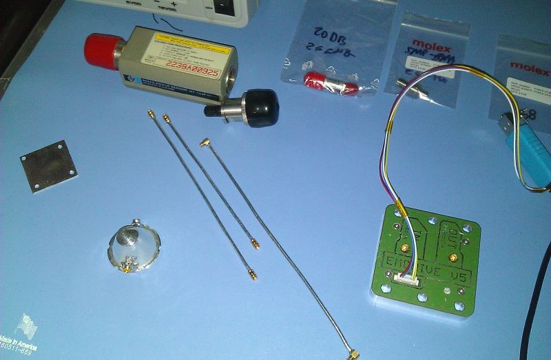
    New EMDrive cavity and board prepared for measurements.
    A precise power sensor, cables (just assembled), adapters and attenuators are all rated for 26GHz.
    I will be able to tell soon exactly how much power the amp is delivering and will be able to measure the cavity properties and resonance condition.
    After these tests I will optimize the feed antenna for maximum power delivery. I will try dipole and loop.
    The cavity has two ports: One with the feed antenna at lambda/4 distance to the big plate and another with a short stub for feedback.

  • Equipment update

    Paul Kocyla12/22/2016 at 08:52 0 comments

    Kein automatischer Alternativtext verfügbar.

    New member in the lab family: A precision power measurement device.
    This device is capable of measung power qualitatively up to 26GHz.
    The funny thing is that although the design comes from 1975, it´ s still in use today and it still has its price. It´s the only thing you can buy to achieve the measuring precision for these frequencies which doesn´t have the price of a new familiy car - 40 years later. At the time of release it was different.
    Sensor head is the 8485a - was lucky to shot one on ebay for half the price they usually go.
    But now finally we get exact measurements for the EMDrive, which will help to optimize the overall design.
    The EMDrive itself will get its own power meter on board - in form of a small chip with less accuracy but good enough to do the job. But until then, this buddy will help to get qualitative results.

    The 26GHz equipment is quite expensive, for example a simple 2.92mm to SMP adapter costs over USD 70 - but it´s important to have the connectors and cables rated for the max. frequency, because in other cases the frequency response of the devices will have notches. Imperfections in the connectors lead to resonances and reflections inside the connectors, the connectors act like a weak cavity.

  • Cleaning up

    Paul Kocyla12/17/2016 at 18:54 0 comments

    The "Flying an EMDrive" project has been removed due to maintenance overhead.
    This doesn´t mean that the EMDrive will not fly - in fact we got a partnership which will make a launch available soon - stay tuned :)

    More details will come later - after we signed the contract

    The things changed a little bit now. We had a test session at TU Dresden with Prof. Tajmar and will establish a lasting partnership.

    The test results are not to be published yet due to an agreement, but what I can say is that the force was not high enough for a reasonable orbit test. The reasons were thermal issues in the high vacuum which caused the amplifier´s TX output power to degrade.
    I made a newdesign with a more efficient amp in an externall box which can be thermally cupled to the scale.

    Here´s the setup:

    I invested some of the funded money in a good used but affordable test equipment going up to 26GHz and will make a careful redesign for a next version V6.

    The paperwork for the satellite launch has been initiated, there´s a lot to do in 2017.

    I plan to do video blogging on the process. I am also expecting trolling as usual, so only constructive comments will be answered.

    The project page will be cleaned up as many of the first steps to get to the current state are not helpful anymore (learning fails).
    If you still need them then feel free to make a backup.

  • EMDrive V5

    Paul Kocyla11/27/2016 at 20:55 3 comments

    The EMDrive V5 board is assembled.
    The metal box can be attached to the scale body for better heat dissipation as we had heat issues during the testing in Dresden. There is also a more efficient amplifier on board which can delliver twice the power than the version V3.
    Now waiting for the new silver cavity to come.

View all 83 project logs

Enjoy this project?

Share

Discussions

jrodal wrote 05/31/2015 at 15:26 point

As I wrote at the NSF EM Drive forum, the ammonia molecule readily undergoes nitrogen inversion at room temperature. The resonance frequency is 23.79 GHz, corresponding to microwave radiation of a wavelength of 1.260 cm. The absorption at this frequency was the first microwave spectrum to be observed.  

Ammonia has been used for Masers at 24 GHz for these reasons: to enhance the power of the signal, since ammonia emits at 24 GHz.

If using ammonia, please follow safety procedures:

Inhalation: Ammonia is irritating and corrosive. Exposure to high concentrations of ammonia in air causes immediate burning of the nose, throat and respiratory tract. This can cause bronchiolar and alveolar edema, and airway destruction resulting in respiratory distress or failure. Inhalation of lower concentrations can cause coughing, and nose and throat irritation. Ammonia's odor provides adequate early warning of its presence, but ammonia also causes olfactory fatigue or adaptation, reducing awareness of one's prolonged exposure at low concentrations.
Children exposed to the same concentrations of ammonia vapor as adults may receive a larger dose because they have greater lung surface area-to-body weight ratios and increased minute volumes-to-weight ratios. In addition, they may be exposed to higher concentrations than adults in the same location because of their shorter height and the higher concentrations of ammonia vapor initially found near the ground.
Skin or eye contact: Exposure to low concentrations of ammonia in air or solution may produce rapid skin or eye irritation. Higher concentrations of ammonia may cause severe injury and burns. Contact with concentrated ammonia solutions such as industrial cleaners may cause corrosive injury including skin burns, permanent eye damage or blindness. The full extent of eye injury may not be apparent for up to a week after the exposure. Contact with liquefied ammonia can also cause frostbite injury.
Ingestion: Exposure to high concentrations of ammonia from swallowing ammonia solution results in corrosive damage to the mouth, throat and stomach. Ingestion of ammonia does not normally result in systemic poisoning.

  Are you sure? yes | no

Leonard Bruce Olin wrote 05/29/2015 at 18:05 point

This may or may not be related to the unknown
physics at work or it may amount to a simpler demonstration of the force involved…   http://gizmodo.com/sunlight-and-graphene-could-one-day-power-a-spaceship-1707535183

  Are you sure? yes | no

simonjwhitaker wrote 05/29/2015 at 04:03 point

I love that you are calling it Baby EmDrive now  :)

  Are you sure? yes | no

biemster wrote 05/26/2015 at 19:24 point

Turns out there is a wiki about the EM drive which I just found and think is very useful as a starting point for newly interested people:

http://emdrive.echothis.com/Main_Page

it also contains a link with a very nice derivation of the resonant frequency of a conical cavity as used in these experiments, useful to determine the optimal dimensions of the frustum:

http://gregegan.customer.netspace.net.au/SCIENCE/Cavity/Cavity.html

beware though that the author of the page behind this last link is very skeptical. I still think that the equations on that page are very useful to determine optimal frequency given certain dimensions of the frustum or vice versa.

  Are you sure? yes | no

nilabrk wrote 05/26/2015 at 03:18 point

Boffins at NSF say fill her up with ammonia gas at 23.79 GHz for double happiness super powers.

  Are you sure? yes | no

Paul Kocyla wrote 05/26/2015 at 06:41 point

Thanx. Do you have a link to that reference?

  Are you sure? yes | no

nilabrk wrote 05/26/2015 at 06:52 point

http://forum.nasaspaceflight.com/index.php?topic=37642.msg1379763#msg1379763

Someone further down timidly wondered if this could be tested on your little guy.

  Are you sure? yes | no

suicidal.banana wrote 05/23/2015 at 10:35 point

Been reading up on this for the past few days, did hear about it in the past but used to be on the 'that cant be right'-bandwagon, things are looking better and better though, and i gotta say i'm impressed that people are trying to create EM drives at home (though i agree that the 'iulian207' youtuber should shield his prototype, this is his blog btw) and actually succeeding at it, even if on small scale.


I found these videos of a presentation by Roger Shawyer from a few months ago, where he talks about a second generation (and also some quite far out idea's, but still decent videos)

  Are you sure? yes | no

flux_capacitor wrote 05/22/2015 at 23:02 point

Why using powers of a few watts only? More exactly: are you carefully going steps by steps, starting with a few watts, before planning to brute-force the EmDrive with say, 100 kilowatts? If so, when? 

With just a few watts, you will measure at best very week thrust signatures, in micronewtons, like Eagleworks, that can be measured only with a very sensitive balance. What would be the point of such an experiment if it's not intended to be ran in a vacuum? The next step, with a 1kW or 2kW magnetron: the same level of thrust will be achieved with a poorly designed cavity. Or perhaps you will be lucky to reach hundreds of millinewtons with a clever designed cavity (frustum machined and polished, high Q with highly reflective gold-plated convex and concave end plates, right design factor, matched adaptative resonance tuning…) and doing so, maybe surpass Shawyer's and the Chinese publicly known devices. This may be felt touching the frustum with the palm of your hand. But again, the measure will be shown by a balance. 

For those thrust levels, people will pertinently keep ranting about spurious causes like experimental errors, EM interactions, ambient air currents, hot air jets, buoyancy and whatnot. And they will keep asking for an expensive CubeSat experiment. They will be right.

So why not trying tens or even hundreds of kilowatts with TWTs or klystrons that are readily available on the market? With 2-3 GHz microwave frequencies at cavity sizes comparable to Shawyer's flight thruster test article. You could also try the 10 to 30 GHz range. This is a little trickier because we still don't know the effect, positive or negative, of higher frequencies on thrust. But at those higher frequencies, the cavity is smaller and lighter so you can stack several of them and let them work together.

Injecting 10-100kW into the frustum, it would get very hot, very fast. This is NOT a problem: just cool it with liquid nitrogen (way cheaper than liquid helium). I'm not saying we need to build a superconducting EmDrive (not yet). Just use a copper or aluminum frustum, and cool it with liquid nitrogen. You don't even need to let it run for minutes. Just a few seconds or tens of seconds will be enough for the generator frequency to lock to the resonant frequency of the thruster, following the initial warm up period. And If your EmDrive jumps and hits the ceiling, It would be interesting to check who, among the jaw-dropped crowd, will raise to claim such a catapult thrust is due to hot air circulating currents.

  Are you sure? yes | no

Paul Kocyla wrote 05/23/2015 at 06:39 point

Ok, we´ll do all these things - next weekend after work ;-)

Seriously - thanx for the ideas. We´ll perform several different experiments. Some of them may be not as convincing but can be achieved very fast, so even if they fail it won´t be wasted time. We can increase the power if the experiment fails. Others require more planning and time. But as we are not an institution with deadlines we just have fun trying it.

  Are you sure? yes | no

BDM wrote 05/20/2015 at 12:03 point

Anyone remember bob lazar and his element 117 waveguide gravity thruster...

http://www.gravitywarpdrive.com/Gravity_Generator.htm

  Are you sure? yes | no

Blaine wrote 05/20/2015 at 15:14 point

Oh yeah, I remember that weirdo.  Dude was unhinged, but it was entertaining.  That said, this has some merit, and it might actually be a real thing. 

  Are you sure? yes | no

Taylor wrote 05/20/2015 at 01:10 point

Will you guys create a tutorial....PLEASE!!!  If you do, it may be what helps nudge the governments of the world to pay attention.  When the EMDrive takes on mass appeal, gears will turn.

  Are you sure? yes | no

Blecky wrote 05/18/2015 at 14:31 point

  Are you sure? yes | no

Paul Kocyla wrote 05/18/2015 at 14:45 point

Wow, nice!
Someone commented that this might be an effect caused by the air inside heating up making the cavity lighter by the hot air balloon effect.
The builder said he will try the device upside down soon.
I am excited if he really got thrust. It´s fantastic if this device really works.

  Are you sure? yes | no

Blecky wrote 05/19/2015 at 05:11 point

Please shield yourself a bit better than that guy :P

  Are you sure? yes | no

Paul Kocyla wrote 05/20/2015 at 18:39 point

Yep. A grounded faraday cage around it should be ok.

  Are you sure? yes | no

Blaine wrote 05/21/2015 at 19:40 point

Turns out its not all about the hot air balloon effect after all! I'm excited.  He posted the results.  Hopefully your team just as well if not better.

  Are you sure? yes | no

Paul Kocyla wrote 05/16/2015 at 10:26 point

That´s a great sheet. Will be very helpful for the big thruster.
I´ll double check it with the reverse engineered values from several pictures.

  Are you sure? yes | no

xobmo wrote 05/11/2015 at 21:50 point

I would love to try and help you with this experiment, as I recently disassembled my microwave oven.  But alas, I have no "cone".  Could this work without the cone?

  Are you sure? yes | no

Mars wrote 05/12/2015 at 04:47 point

Watch... it'll just so happen some common plumbing part has the optimal cone shape for this...  http://www.homedepot.com/p/Unbranded-Everbilt-Water-Heater-Vent-Hood-EB40665/204834530

  Are you sure? yes | no

Paul Kocyla wrote 05/12/2015 at 08:59 point

Thanx for the hint. The cone has to be calculated according to the feed frequency, else it won´t work. We will machine cones for 2.45 GHz and for 25 GHz

  Are you sure? yes | no

Mars wrote 05/12/2015 at 18:32 point

I'm curious as to how it scales.  Do the relative dimesions scale with frequency (the cone slope change), or is there an optimal shape that just scales up and down in size?  If the cone is close enough, maybe you can tune the RF to match the cone.  (I don't know if you can 'tune' a magnetron like other RF generators)

  Are you sure? yes | no

Paul Kocyla wrote 05/12/2015 at 20:59 point

It should scale linearly, because - according to the paper - the cavity is a deformed resonator. They give a formula to calculate the quality factor. Anyway they propose to alter the diameters and height and the wave injector values within some range to tune the optimum resonant frequency.

(The asymmetrical structure alters the resonance frequency, so they propose to alter the height of the cone for cmpensation)


A good frequency tuning would be a nice feature, but many affordable rf sources don´t have that feature.

  Are you sure? yes | no

biemster wrote 05/14/2015 at 18:56 point

Could you maybe write this quality factor formula you mention and this diameter and height tuning procedure in the project log? Or perhaps a ref to the paper?

  Are you sure? yes | no

Paul Kocyla wrote 05/17/2015 at 20:42 point

It´s a deformed waveguide, so it scales linearly according to the wavelength.
But there are for sure many factors depending on material, wall angle and the whole geometry.
I think there is no existing optimal formula yet. You can compare it to the first experiments with aviation. It took a long time from first experiments with functional wings to advanced simulation models. That´s the exciting part about it. It´s something new do discover :)

  Are you sure? yes | no

xobmo wrote 05/17/2015 at 03:05 point

During the first two weeks of April of this year,  NASA Eagleworks may have finally obtained conclusive results.  This time they used a short, cylindrical, aluminum resonant cavity excited at a natural frequency of 1.48 GHz with an input power of 30 Watts.  (in the NASA article.)  So you may be able to use a different style/easier to machine cavity.

  Are you sure? yes | no

Leonard Bruce Olin wrote 05/11/2015 at 18:45 point

When big breaks in science and technology occur,
there are many examples of simultaneous discoveries. For example, calculus was
independently invented by Newton and Leibniz, evolution recognized by Darwin
and Wallace. While looking more deeply into the Eagleworks story, I noticed
some material I had overlooked about some physics professor in Omaha making the
same sort of warp bubble phenomena producing FTL measurements in a laser beam
fired into his device. Could the two different types of devices have something
in common (asymmetric EM fields)?  http://www.geeksnack.com/2015/03/10/functional-warp-drive-apparently-bending-space-time-omaha-garage/

  Are you sure? yes | no

Neil Farbstein wrote 05/10/2015 at 22:06 point

CHEMONUCLEAR  FUSION CAN POWER  EM Drive spaceships.


Chemonuclear Fusion is a type of low energy nuclear fusion that has
been shown to produce energy in two experiments. Aneutronic nuclear
fusion can provide unlimited electric power without polluting the
environment with radioactive waste and greenhouse emissions.
Chemonuclear processes in small dense white dwarf stars accelerate
the rate of nuclear fusion and cause them to explode in spectacular
supernova explosions.


The Chemonuclear Fusion Project is soliciting
volunteers to help our crowdfunding and educational campaigns. Our
crowdfunding webpages will soon be up and running. We want people to
post to discussion groups and help us get the word out that
aneutronic chemonuclear fusion might be the radiation free way to
power the world if we can get the funding to build and test
reactors.

We want artists who can help us design T-shirts,
mugs, and promotional items to sell and give away to our
contributors. Writers to write promotional materials and post to web
forums are also wanted. Video producers and professional and amateur
scientists who can help the public understand the concepts of
chemonuclear fusion are encouraged to contact us also.

Visit our facebook page
and give us a like. We welcome your comments and questions!

https://www.facebook.com/chemonuclearfusionproject

  Are you sure? yes | no

Paul Kocyla wrote 05/11/2015 at 07:55 point

This sound pretty esoterical - but on the other hand, the EMdrive was also considered as esoterical. I wish that it works.

  Are you sure? yes | no

Neil Farbstein wrote 05/10/2015 at 21:50 point

The Shawyer stuff I read doesn't talk about quantum plasma. Its somebody else's  theory. 

I have'nt seen anything credible about  bubbles in space time. Nothing deep in the published. literature.

  Are you sure? yes | no

Boz wrote 05/10/2015 at 21:21 point

Good luck.. Looking forward to taking the engine out of the spare car and making it vacuum proof :-)

You really should do a kickstarter for this, a lot of people out there would chip in...

  Are you sure? yes | no

[deleted]

[this comment has been deleted]

Paul Kocyla wrote 05/10/2015 at 20:25 point

Ok. I´ll choose a microwave where I won´t need to open the casing.
I´ll use a waveguide to pick up the RF from the internal waveguide in the cook chamber.

  Are you sure? yes | no

Neil Farbstein wrote 05/10/2015 at 17:10 point

Th eagleworks announced it will publish results of their ;latest tests in two months in July.

  Are you sure? yes | no

Paul Kocyla wrote 05/10/2015 at 18:12 point

Great. Excited to see them.

  Are you sure? yes | no

Neil Farbstein wrote 05/10/2015 at 16:58 point

Roger Shawyer now says that there is limit to the speed that his EM thruster can develop before it starts eating up huge amounts of energy and its efficiency goes way lower. It has to do with special relativistic dynamics . Can somebody tell me if this is correct?

 My understanding is that at higher speeds the reference frame of the back resonator wall is catching up with the slower group velocity microwaves and nullifying the effect of differential group velocities. So less electromagnetic pressure is being exerted on the front wall of the resonator.  Is that going on at  subrelativistic speeds?

  Are you sure? yes | no

Paul Kocyla wrote 05/10/2015 at 20:31 point

I don´t exactly know the theory. Maybe the density of the vacuum virtual plasma is changing with increasing speed.

  Are you sure? yes | no

Similar Projects

Does this project spark your interest?

Become a member to follow this project and never miss any updates