Close
0%
0%

EMDrive/satellite

Developing a small fuelless microwave thruster

Similar projects worth following
The EMdrive is a new type of thruster - recently invented by Roger Shawyer & Guido Fetta.
Unlike other propulsion systems which need to repel mass to produce thrust, the EMdrive can convert electrical energy into thrust directly.

There are endless uses for an EMDrive - in terrestric and in space applications.

A working EMdrive would start a revolution in spaceflight, enabling manned deep space exploration.

Several builds have been made worldwide (eg Chinese University, NASA), many show positive results. This topic is still quite new and needs a lot of research.

Most EMdrive builds work with frequencies around 2.4 GHz because a high power RF source for them can be made out of a microwave oven magnetron.
My attempt is is to build one which works with 24GHz, which reduces the form factor significantly and makes it possible to be used in small satellites.
A so small EMdrive could be flown to space for 20000$ on a pocketqube satellite.

OVERVIEW

-------------------------------------------------------------------------------------------

The EMdrive is derived from a closed cylindrical microwave waveguide. The main difference is that one end is larger than the other. When RF is fed into the cavity and a resonance is achieved - according to Shawyer a thrust force will occur.

---

The first builds have not been summarized due to documentation cleanup process

---

EMDrive V3

===============================================

The V3 is a silver cavity build, fed by a fully controllable RF source capable of beeing tuned between 22 and 26 GHz.

The reflected power can be measured in amplitude and phase.

First measurements with acoustic vibrations (by OOK modulation of the RF source) show a force near the designed target resonance frequency. The last experiment is reproducible and shows clear signals. Further tests must be performed to check for directivity of the force.

PS: Many many thanx to all the people who gave us very helpful hints how to improve the system. It has been an exciting ride for us until now, and we hope to provide a functional Baby-EMdrive soon

Special thanx go to TheTravellerEMD, Marvin Macportain, Keegan Reilly, Aurelio Chargb Ramos

EMDrive V4

===============================================
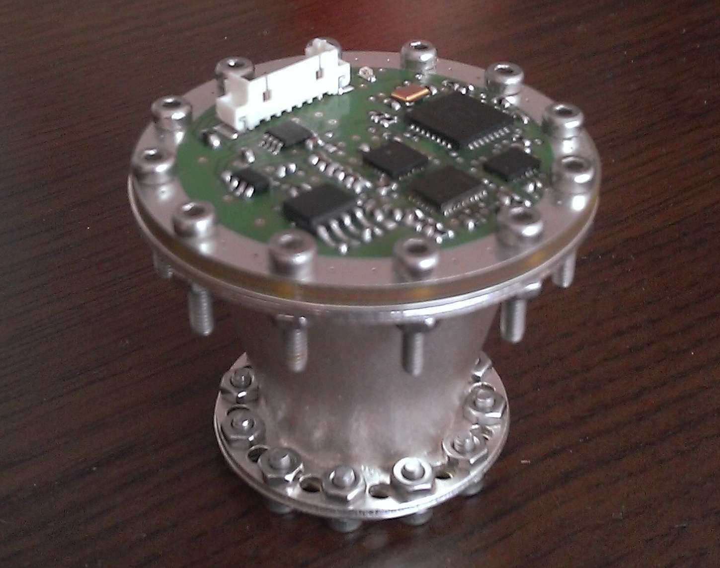
This build was a complete integrated version which has been tested at the TU Dresden with Prof. Tajmar.
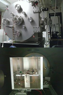
It should have been the flight version for our satellite in case the test would heve been more successful.

We had thermal issues during testing, with temperatures of the amplifier rising up to 90°C.

This led to a massive power derating in the amp.

We had to reduce power to keep the temperature low, so the final force was only slightly above the scale´s resolution.

Other effect like lorentz forces and thermal deformation had a significant pattern in the measure plot.
Tests have been made for 0°, 180° and 90°
Results are not for publilcation yet - we will perform further tests with version 5.

EMDrive V5

===============================================

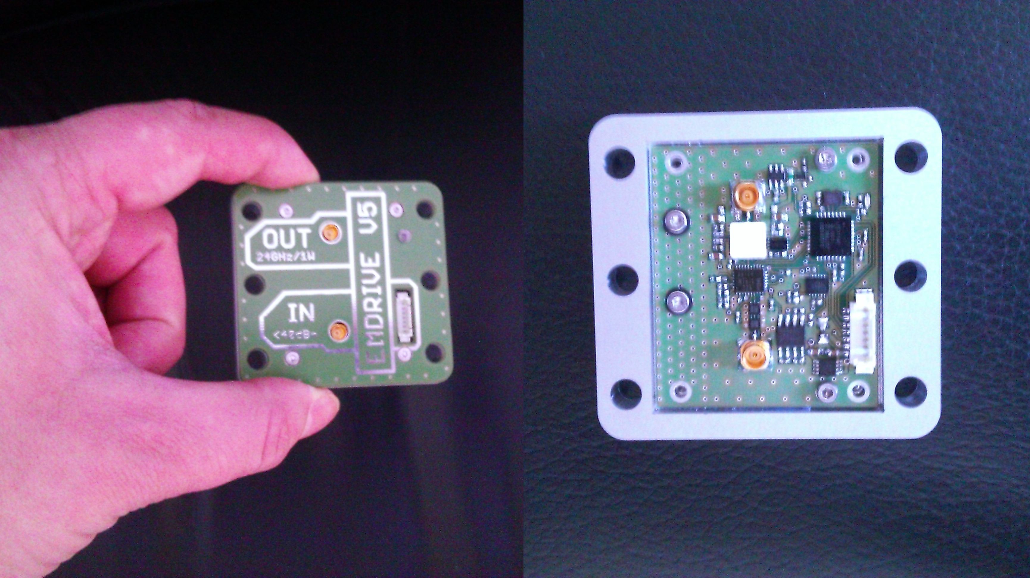
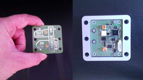
This is a development unit - derived from the V4 - which is intended to be tested at TU Dresden. It has some improvements to solve the problems that we had during testing of the V4.

It has an amplifier with better efficiency and is well thermally coupled to the casing for better heat management.

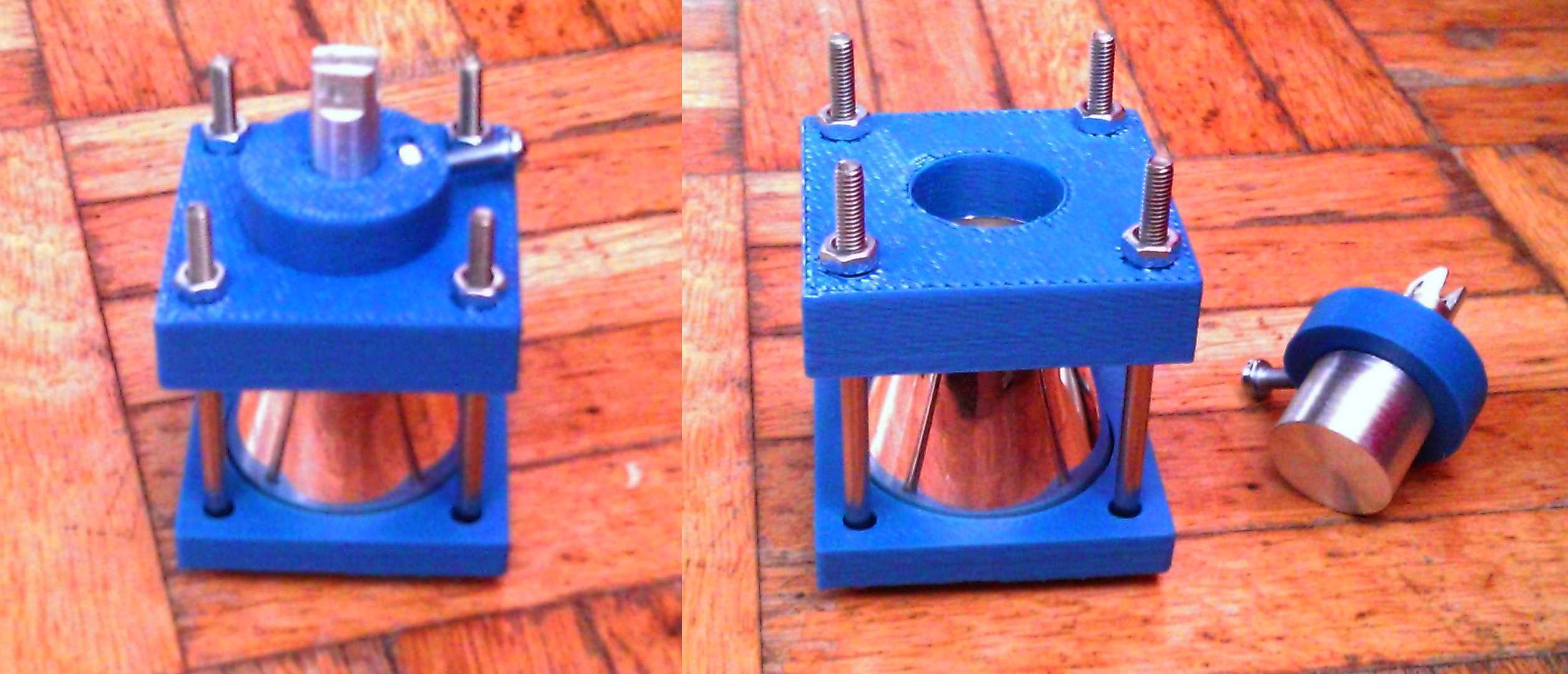
The new silver cavity geometry has an improved shape based on a proposal in Shawyer´s actual patent paper.

This shape will ensure that the pathlengths of the reflected waves on the longitudinal axis of the cavity is always kept to a multiple of lambda/2 of the resonance frequency.
  • New kind of thruster in development

    Paul Kocyla07/19/2017 at 20:34 1 comment

    Just a quick update after a long time:

    The Dresden University will probably continue measurements on the BabyEMDrive thruster with an improved torsion scale. It can resolve 20nN.

    Please check out another promising technology for propellantless propulsion. I decided to share the development and tests on a Mach Effect Thruster:

    https://hackaday.io/project/26013-mach-effect-thruster-xperiments

  • Tests

    Paul Kocyla03/23/2017 at 21:20 1 comment

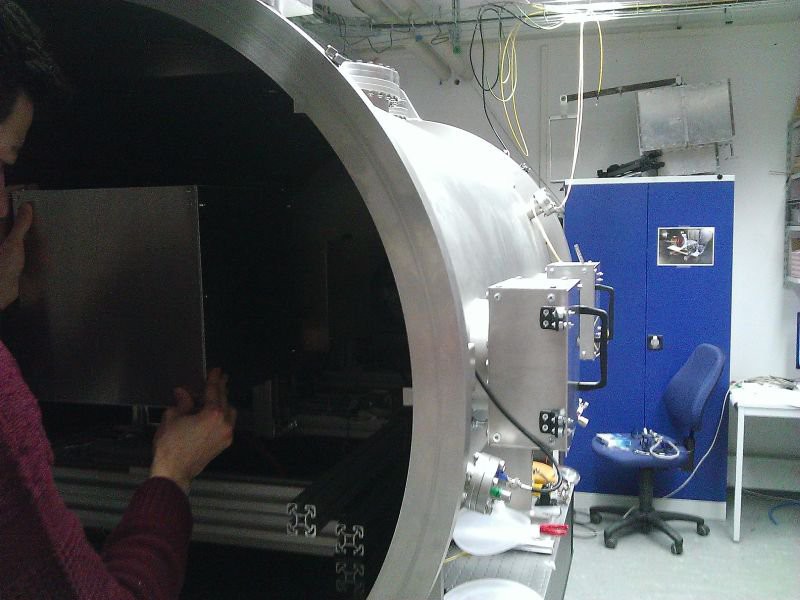
    In February the EMDrive V6 has been under test on the Technical University Dresden.

    As the pretest-board didn´t output the expected power, I made a quick redesign right before the test date.
    The output after a day in vacuum was around 500mW, that´s "only" 3dB less than the desired 1000mW. Not so bad for a simple 4-Layer board.
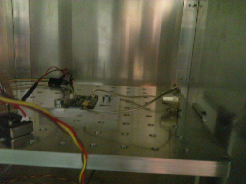
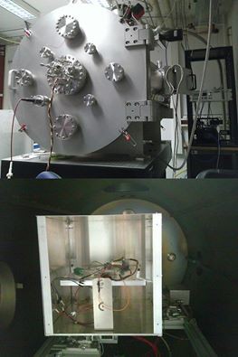
    Here is the board inside the scale box:
    I am not allowed to publish detailed results, but some information upfront:

    The thermal drift was much bigger than the possible thrust - anyway the force is depending on the frequency and seems - I say seems because that´ s only a quick observation - to be proportional to the amplitude of the resonance peaks.
    I was only able to spend two days in Dresden so the following long duration tests has been made without my presence.
    Possible forces are lower than 0.1µN, it´s still not 100% to say without eliminating the thermal drift, so we have to wait until this problem is solved.
    The thermal drift shows always in the same direction and disturbs the interesting signal into uncertainty. So thrust is not confirmed but also not busted yet.
    From my side - the Baby EMDrive is completed, unless an affordable amplifier with a significantly higher power appears.
    There is an IAC abstract from Prof. Tajmar submitted about this EMDrive with details available on the conference beeing held in September this year in Australia.
    Thanx to the many interesting discussions and suggestions.
    Special thanx go to Prof. Tajmar, Matthias Koessling and Marcel Weikert for making the measurements possible, and Dave, who boosted the project by financial help - hope we get some thrust out of it so we can send it to space.

  • Pre-Test smulations

    Paul Kocyla02/05/2017 at 16:18 1 comment

    Jamie (monomorphic) ran a simulation on the new EMDrive V5 cavity model. Great work and many thanx!
    He detected two modes - would correspond with my two resonance peaks on the real thing.

    Kein automatischer Alternativtext verfügbar.

    Kein automatischer Alternativtext verfügbar.

  • New board ready for testing

    Paul Kocyla02/02/2017 at 22:42 3 comments

    The last board showed some power leak. The expected power could not be reached. It even degraded to 40mW - bad. Now I made a new board with better connectors and more careful routing which is ready for testing in Dresden.

    It is prepared for the highly sensitive scale and can deliver more than 200mW with 24GHz at 85°C (after cable- and connector lossed), so we should not get thermal issues this time. The ALU-Plate will be also fixed to the scale for better heat dissipation.The cavity is new (blogged about it before). It shows two clean resonance peaks at which we will test for thrust.
    Sweeps will also be made in case there are some other phenomena which may occur beside the two resonance frequencies.
    For an eventual integration into a satellite, the board can find and track the resonance peaks automatically.

    I´ll make a 360° video of the test preparation in Dresden (if allowed).

  • Measurement followup

    Paul Kocyla01/06/2017 at 06:07 1 comment

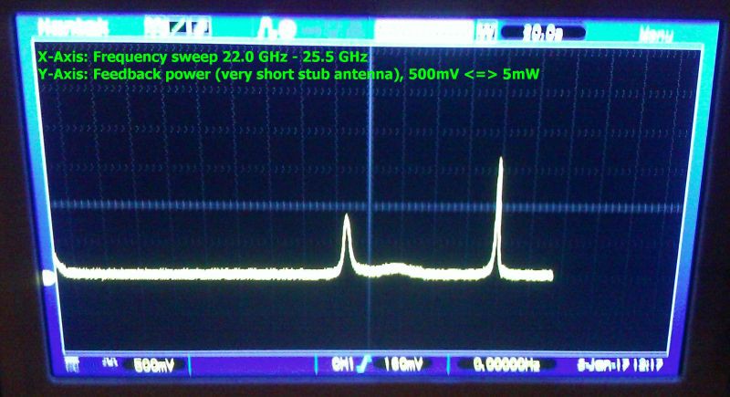
    Improvement in cavity resonance after simplifying the feed antenna:

    In the previous measurements I soldered a stub to the feed connector to reach lambda/4.
    In this configuration, this stub is missing. The feed pin is shorter than lambda/4 and its angle is the angle of the cone wall.
    There are only two peaks now, the first was also visible before, the second has a more narrow bandwidth and higher amplitude.

    Probably these peaks represent two different cavity excitement modes in this frequency range.

    We will track both of them in the next test session.

  • Cavity V5 measurements

    Paul Kocyla01/03/2017 at 21:19 5 comments

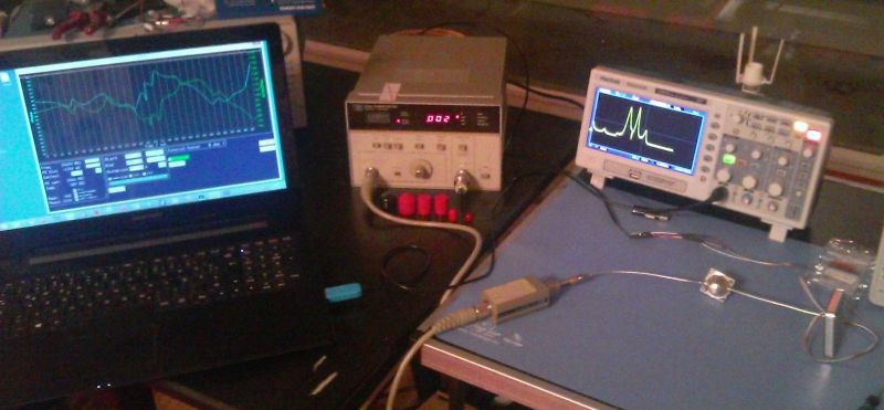
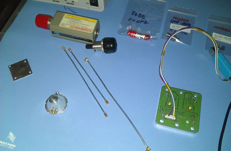
    Here is the setup:

    The EMDdrive V5 board is connected to the cavity´s feed antenna (lambda/4 stub).

    A shorted antenna is used as feedback port which is connected to a power sensor.

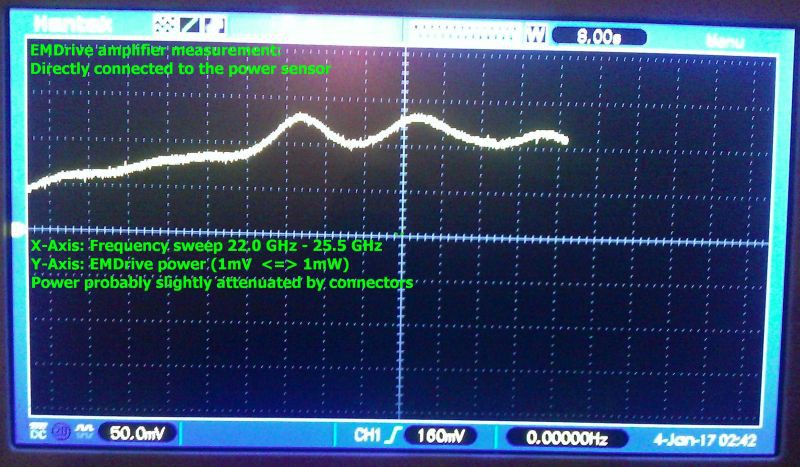
    First, I measured the amplifier´s performance by connecting it directly to the power sensor.
    Here are the results:

    At over 23.5 GHz the power is over 100mW - hmmmm it´s a 1000mW amplifier, so that´s not that good, the board is probably not perfectly designed, cables and connectors have losses. The sensor has a 20dB attenuator (compensated calculations for that) and a SMP to 2.92mm adapter, they will probably also cause some losses. So let´s say it´s around 150mW at the working frequency range.

    Now comes the interesting part: The feedback port is connected to the sensor, and frequency sweeps are performed. It´s basically a scalar network analysis.
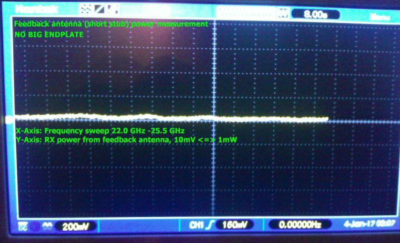
    First, I left the cavity opened - this means the big endplate was not connected.
    Here is the result - flat, almost no feedback. That´s not surprising, should be like this:

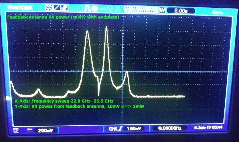
    Look what happens when the big endplate is attached:

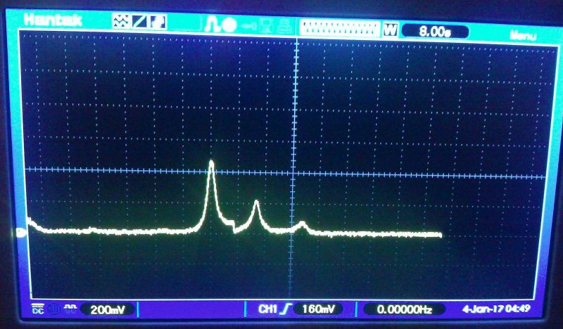
    We get three main peaks. Two strong and one weak - and some smaller artefacts.

    I assume the small disturbances are caused by the antennae destroying the optimal shape of the cavity.

    When you look at the power level, it seems that the feedback antenna is sucking all the power out off the cavity, not good, it was probably too long - but better starting off too long than too short. So I cut the feedback antenna shorter, from around 1.7 mm to 1mm (approximately). Here´s the result:

    That´s better. The feedback antenna now sucks 40mW instead of 100mW. That´s better, but still too much.

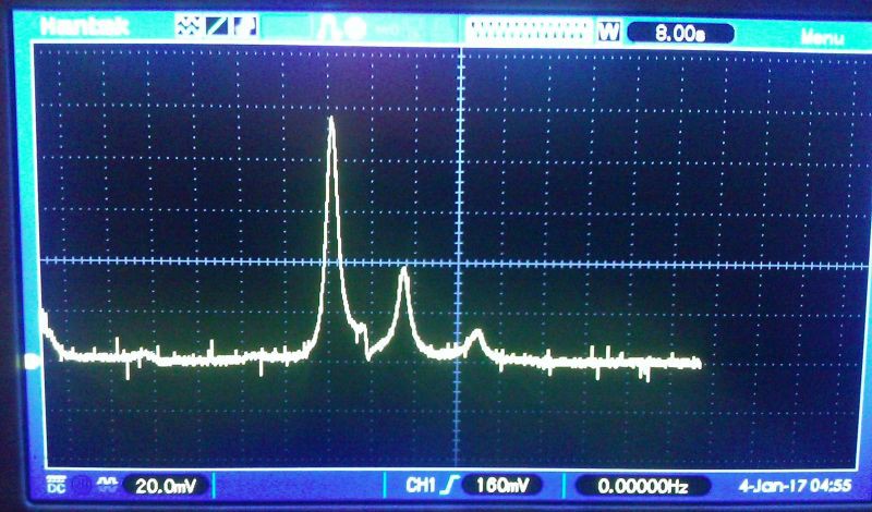
    Now I cut the antenna to the ground, it´s just a pin in the hole, but the result seems ok:

    Note that the V/div is now 20.0mV instead of 200mV, so it´s sucking just 10mW now.

    Probably some room for improvement here - let´s see, but that´s acceptable.

    BTW before the trolls cry again because of missing axis labels: The two last pictures have same labeling than the third last - I´m just too tired to insert them - have a newborn baby now and a full time job: X:FRQ sweep, Y: power 10mV <=> 1mW

  • EMDrive V5 and cavity prepared for testing

    Paul Kocyla01/02/2017 at 20:48 0 comments

    New EMDrive cavity and board prepared for measurements.
    A precise power sensor, cables (just assembled), adapters and attenuators are all rated for 26GHz.
    I will be able to tell soon exactly how much power the amp is delivering and will be able to measure the cavity properties and resonance condition.
    After these tests I will optimize the feed antenna for maximum power delivery. I will try dipole and loop.
    The cavity has two ports: One with the feed antenna at lambda/4 distance to the big plate and another with a short stub for feedback.

  • Equipment update

    Paul Kocyla12/22/2016 at 08:52 0 comments

    Kein automatischer Alternativtext verfügbar.

    New member in the lab family: A precision power measurement device.
    This device is capable of measung power qualitatively up to 26GHz.
    The funny thing is that although the design comes from 1975, it´ s still in use today and it still has its price. It´s the only thing you can buy to achieve the measuring precision for these frequencies which doesn´t have the price of a new familiy car - 40 years later. At the time of release it was different.
    Sensor head is the 8485a - was lucky to shot one on ebay for half the price they usually go.
    But now finally we get exact measurements for the EMDrive, which will help to optimize the overall design.
    The EMDrive itself will get its own power meter on board - in form of a small chip with less accuracy but good enough to do the job. But until then, this buddy will help to get qualitative results.

    The 26GHz equipment is quite expensive, for example a simple 2.92mm to SMP adapter costs over USD 70 - but it´s important to have the connectors and cables rated for the max. frequency, because in other cases the frequency response of the devices will have notches. Imperfections in the connectors lead to resonances and reflections inside the connectors, the connectors act like a weak cavity.

  • Cleaning up

    Paul Kocyla12/17/2016 at 18:54 0 comments

    The "Flying an EMDrive" project has been removed due to maintenance overhead.
    This doesn´t mean that the EMDrive will not fly - in fact we got a partnership which will make a launch available soon - stay tuned :)

    More details will come later - after we signed the contract

    The things changed a little bit now. We had a test session at TU Dresden with Prof. Tajmar and will establish a lasting partnership.

    The test results are not to be published yet due to an agreement, but what I can say is that the force was not high enough for a reasonable orbit test. The reasons were thermal issues in the high vacuum which caused the amplifier´s TX output power to degrade.
    I made a newdesign with a more efficient amp in an externall box which can be thermally cupled to the scale.

    Here´s the setup:

    I invested some of the funded money in a good used but affordable test equipment going up to 26GHz and will make a careful redesign for a next version V6.

    The paperwork for the satellite launch has been initiated, there´s a lot to do in 2017.

    I plan to do video blogging on the process. I am also expecting trolling as usual, so only constructive comments will be answered.

    The project page will be cleaned up as many of the first steps to get to the current state are not helpful anymore (learning fails).
    If you still need them then feel free to make a backup.

  • EMDrive V5

    Paul Kocyla11/27/2016 at 20:55 3 comments

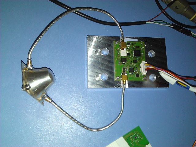
    The EMDrive V5 board is assembled.
    The metal box can be attached to the scale body for better heat dissipation as we had heat issues during the testing in Dresden. There is also a more efficient amplifier on board which can delliver twice the power than the version V3.
    Now waiting for the new silver cavity to come.

View all 83 project logs

Enjoy this project?

Share

Discussions

hobbesalpha1 wrote 09/28/2015 at 00:47 point

Hello again, hope I am not bothering, but are you referring to this when you say fixed plate cavity
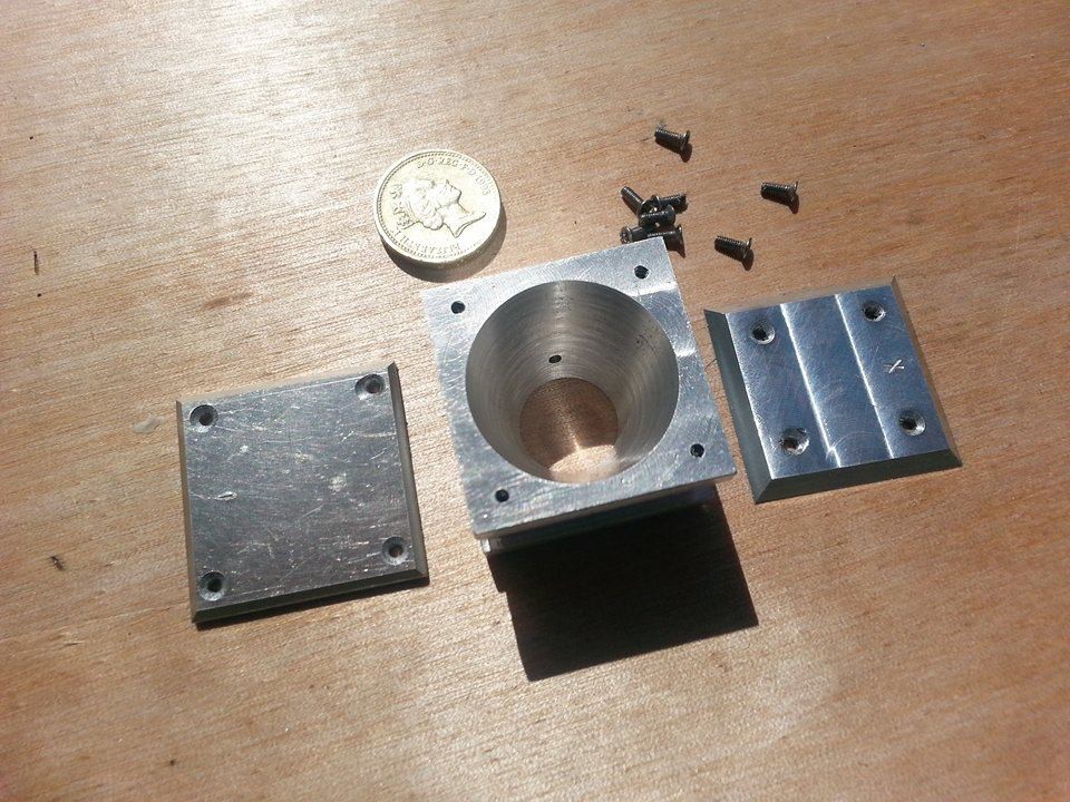
 ?

  Are you sure? yes | no

Paul Kocyla wrote 09/28/2015 at 06:05 point

No, it´s the new one, just without the tuning screw. Instead, there is a metal plate at the end. I took a picture, but somehow can´t post it here, drag and drop doesnt do it.

  Are you sure? yes | no

hobbesalpha1 wrote 09/28/2015 at 09:45 point


You mean this one? Didn't see the big plate side, is it like the one with the adjustable screw where the big plate is covered? Also try pasting the link :)

  Are you sure? yes | no

Paul Kocyla wrote 09/28/2015 at 11:09 point

Yes, it´s this one. Still can´t paste the pic. Maybe it´s my browser.

  Are you sure? yes | no

willemstaal wrote 09/29/2015 at 11:06 point


 i just found out how to paste images: just copy  the link into the reply field..  And if you want to use a picture on your computer: stash it first on a imageserver like tinypic or similar.

  Are you sure? yes | no

TheTravellerEMD wrote 09/23/2015 at 07:39 point

Paul. 

When the freq hits frustum resonance, initially the empty cavity will appear to have 0 impedance (act like a short, reflecting back all Rf) and then over 5 TCs fill to max capacity. 1 x TC seconds = (2 Qloaded) / (2 Pi freq). Should add that after the frustum is filled and the Rf is turned off, the frustum's energy will flow back to the Rf generator (taking 5 TCs) and become heat.

So even without measuring Force generation, you should be able to do a sort of rtn loss scan to search for and map out frustum resonances by just monitoring for current spikes as the frustum absorbs Rf energy. If you can measure reflected power can then get VSWR & maybe tune for best VSWR.

You should be doing this frustum resonant freq mapping and lowest VSWR tuning 1st, before looking for Force generation. Why? Cause if you don't get the 1st 2 steps right, you may find it hard to get Force generation.

  Are you sure? yes | no

Paul Kocyla wrote 09/23/2015 at 10:51 point

Thanx a lot. I´ll look if i can implement that. I´ll have to do a firmware change on the RF board to get this data fast enough. Currently I can just send and receive via 9600bps UART. I put a stub antenna near the connector to the RF cable, so maybe I can measure VSWR through it indirectly.

  Are you sure? yes | no

TheTravellerEMD wrote 09/23/2015 at 10:54 point

Can you measure reflected and forward power?

  Are you sure? yes | no

Paul Kocyla wrote 09/23/2015 at 11:00 point

I can measure the current to the PA and (indirectly) the leaking power from the power amplifier output (via a stub antenna) near to the connector. The current is the yellow graph in the charts, the RX power is the blue graph (not sure about the polarity and absolute value, these are only ADC values)

  Are you sure? yes | no

TheTravellerEMD wrote 09/24/2015 at 11:20 point

Paul. 

You need 100% to get access to a VNA and run a S11 rtn loss sweep across your Rf gens freq range. From that you should get resonant freqs and rtn loss dBs or VSWR. To get Force you need to KNOW you have BOTH resonance and low VSWR at the resonant freq, otherwise you will be chasing ghosts.

As you can vary Freq, would suggest you consider building in a forward & reflected Rf measurement circuit. Plenty of examples on the net. Then you can tune the freq for highest rtn loss dBs / lowest VSWR and measure your frustum Q, VSWR, forward & reflected Rf power in real time.

Then getting a good Force generation should be relatively easy.

  Are you sure? yes | no

hobbesalpha1 wrote 09/23/2015 at 03:27 point

Any indication as to where the thrust is vectored? Is it to the smaller end or larger?

  Are you sure? yes | no

Paul Kocyla wrote 09/23/2015 at 06:31 point

I don´t know. Although I can see in which direction the interference rings are going, it´s hard to determine in which direction the rig goes, without having a reference.

I can try to hold a magnet to the rig and attract it into a defined direction. Then I´d see in which direction the rings are going. This might work.

  Are you sure? yes | no

hobbesalpha1 wrote 09/23/2015 at 12:26 point

Reason why I ask is if you can determine if the force is forward or if the force is backward really helps. If the force diagrams and the original theory is to be believed. It doesn't matter the drive configuration, it should always be pointing forward, or if you fitted the drive on a track it would be moving with the small plate being the front. If instead it was moving backwards, or with the large plate being the front, I believe at that point you have discovered something akin to an inverse drive. That would be almost far better then a zero drive in learning how this thing actually ticks.

  Are you sure? yes | no

Paul Kocyla wrote 09/23/2015 at 13:42 point

Yes. For the next tests I will check in which direction the platform moves according to the interferometer rings, so we´ll know which endplate is leading. Then I´ll make tests with just the cavity turned around, and we´ll see if the forces inverses too.

  Are you sure? yes | no

Paul Kocyla wrote 09/25/2015 at 09:29 point

Thanx for the accurate explanation. I´ll try to use the existing hardware to make the RF measurements you propose.
In future, I´ll make another board capable of doing this. The problem is, that the 24GHz range is much harder to handle than lower frequencies. I´ll have to use specialized ICs , a discrete build is imho impossible in that band.

Finding someone with a VNA would be great, maybe I can ask at the university, we got a good HF institute here.

  Are you sure? yes | no

malvasio wrote 09/16/2015 at 19:06 point

i'm curious about what happen if 24 magnets turn around the cone at 1GHZ ...

  Are you sure? yes | no

Paul Kocyla wrote 09/17/2015 at 06:24 point

They will become plasma, but probably they will desintegrate within nanoseconds :-D

  Are you sure? yes | no

malvasio wrote 09/17/2015 at 09:23 point

Paul your magnets are too strong
very small coils and alternative electricity should mimic it without destroy
can you make a small module in openscad to give peoples easy stl of cones for any wavelength of interest in EM* ?
you can't test anything that can pop in mind of anyone ;)

  Are you sure? yes | no

Paul Kocyla wrote 09/17/2015 at 21:32 point

Yes, we´ll post the OpenScad files for the cavity - actually it´s almost a one-liner, cause the cylinder procedure expects two radius parameters anyway.

  Are you sure? yes | no

malvasio wrote 09/18/2015 at 11:32 point

Paul i asked a module not 1 cone.scad ;)

i know openscad is simple

i can only use it : i'm too handicapped to correctly use a mouse or touchscreen

but i don't know the math to make correct size for any resonnator cone for any wavelength that have an interest in EM*

it should take you less than 3 hours ...

  Are you sure? yes | no

willemstaal wrote 09/14/2015 at 10:53 point

Paul, i have a question about the densities of the materials you use:

copper has a density of 0.324  lb/in3 (the material Shawyer uses copper for his cavity

silver has a density of  0.379   lb/in3 

Does this have a affect on the overall measurements?

  Are you sure? yes | no

Paul Kocyla wrote 09/14/2015 at 13:39 point

I don´t think so. But the conductivity is important, because it has direct effect on the Q factor. Silver has a slightly better conductivity than copper, so given two identical cavities, one of silver one of copper, the silver one would have a better Q factor.

  Are you sure? yes | no

willemstaal wrote 09/14/2015 at 13:48 point

So a cavity of thermal pyrolytic graphite would be even better! and a less weight too!

  Are you sure? yes | no

Paul Kocyla wrote 09/14/2015 at 14:05 point

Don´t mix electrical conductivity with thermal conductivity. Pyrolytic graphite is a poor conductor.

  Are you sure? yes | no

willemstaal wrote 09/14/2015 at 14:09 point

not if you give it a galvanic coat of of silver..

  Are you sure? yes | no

hormelbob wrote 09/11/2015 at 01:14 point

Hey Paul, I've been wondering - what do you predict the maximum thrust from this scale version of Shawyer's EMdrive will be (is it 100g)? Also, what is the scale of your device compared to Shawyer's original thruster?

  Are you sure? yes | no

Paul Kocyla wrote 09/11/2015 at 06:00 point

Scale is about 1:10

According the thrust: Shawyer´s thrust force (fed with several hundred watts) was 0.2-1g.
We are feeding with max.500mW and expect something in the µg range. The forces are very tiny, that´s the reson why we build an interferometer arund it.
Nevertheless, even these tiny forces have a big value in space - because you don´t need fuel, you can run the thruster theoretically forever as long as there is electrical energy available (sun, nuclear)

  Are you sure? yes | no

hormelbob wrote 09/11/2015 at 17:47 point

Thanks, that is so cool! I can't tell you how excited I am to see the results (or lack thereof). If you confirm thrust, do you have any other experiments in mind? The effect of thrust on another object (a feather, for example), placing the device on a rail to see if it can move itself? etc.   

These kinds of ideas only brings up another question, according to your specs, is this drive even capable of moving itself inside and outside of a vacuum in a meaningful way? I get that in the vacuum of space, any force, however tiny can push the drive (which is cool) but people are getting excited (prematurely so) about alternate applications (to include terrestrial) and other such claims like a hypothetical limit of .66 the speed of light, which seems unlikely. At this point in time, even if thrust exists, the force being generated seems rather weak, so such speculations really feel counter intuitive to what I have observed from Shawyer's videos and other DIYs. 

On another note, I can't help but notice no one is discussing your DIY build with the others setups on the SubReddit forum for EMdrive: https://www.reddit.com/r/EmDrive/

I'm sure there are a lot of people there who would be interested in your project.

Thanks

  Are you sure? yes | no

Paul Kocyla wrote 09/11/2015 at 18:37 point

There was a big discussion on reddit, and we got many comments, hints and help from the people there. For example TheTraveller who calculated the stuff for Roger Shawyer.
Maybe the pause in discussion is that we were building our new setup which is almost - but still not - ready, so there were and are  no results available at this time.
There are several builds worldwide which measured some thrust, but it´s still not proven that this thrust came solely from the EMdrive and was not any parasitic force.
We are just another group trying to verify the theroy and trying to build a working setup. We plan to run the tests before the semifinals deadline on September 21st 2015

If there really is a tiny force - whoever proves that - then there is a good chance to develop an emdrive (with a superconducting cavity) that is capable of realizing the dreams of frictionless terrestric application like personal flying devices etc.
It´s like the invention of the steam engine which pushed the industrial revolution. 

This topic is quite new, it might prove wrong, but it might also prove right and give us another science fiction technology which might change the world.

If we really confirm thrust, then we will develop a flight version and hope to put it into a cubesat or pocketqub satellite. We willdefinitely send up a satellite with an EMdrive into space in case we win the Hackaday Prize - but don´t count goals that havent been shot yet :-D

  Are you sure? yes | no

hormelbob wrote 09/12/2015 at 22:19 point

Absolutely, Paul. Thanks and goodluck. Until then I'll stay tuned

  Are you sure? yes | no

willemstaal wrote 09/09/2015 at 14:10 point

To ensure you have a stable system try to comparise your beam like this:

Try to focus the laser on a small droplet of mercury and bounce that onto the splitter . Measure that . If the despersion  moves  the same amount as your em readings that your result can have a error caused by trembles. Mercury will react on any force that moves it. You will see fringes.

  Are you sure? yes | no

Paul Kocyla wrote 09/11/2015 at 06:03 point

Mercury is not so harmless, I´ll try the simple approach first.

  Are you sure? yes | no

Chris wrote 09/11/2015 at 11:27 point

Alloys of gallium, indium and tin are harmless and liquid at room temperature.  You can use that in place of mercury: https://en.wikipedia.org/wiki/Galinstan

  Are you sure? yes | no

willemstaal wrote 09/08/2015 at 06:39 point

 I was thinking about the Koch island patch resonator and i suddenly remembered a Book about Fractals written by Denny Gulik a few year ago who, he was  talking about a curious phenomena that was observed by (as i remembered well) Christian Huygens in the 16th century, who notized that pendulum clocks syncronise themselves at some intervals.

Nobody knows how, but it happens.

Now my theory about this is,  that this phenomena can occur  in the cavity too, on atomic levels.
A nice experiment would be to try to modulate the frequenty of the microwaves (if your able too) to make a alternating resonator.

  Are you sure? yes | no

John Rhodes wrote 09/06/2015 at 15:59 point

This question might be obvious but where can I find a parts description, etc

  Are you sure? yes | no

Paul Kocyla wrote 09/06/2015 at 16:07 point

We are posting every update in the project logs, there´s a lot of valuable information already.
As the 2015HackadayPrize is running, there is no time to write descriptions now, we have to build up the setup.
The detailed descriptions will follow after the next deadline, including part lists, CAD files for 3D printed parts and more detailed instructions how to build the setup.

UPDATE: Much information can be found here: http://emdrive.wiki/Main_Page

  Are you sure? yes | no

malvasio wrote 09/05/2015 at 08:37 point

oops i didn't understood that the cone is one cavity 

it is much more complicated then to add a second resonator

did you test the resonance Paul ?

  Are you sure? yes | no

Paul Kocyla wrote 09/06/2015 at 07:47 point

Our previous setup was not able to test for resonance, and it was not tuneable.

The new setup has two methods of testing for resonance. We can measure the current of the power amplifier, which changes with SWR and we can detect RF energy directly which comes back from the feed with a small stub antenna near to the feed connector trace on the PCB. Both have been tested in the lab, but not yet in the cavity. Our new setup is still beeing built, but we aim to perform first tests before September 21st for the semifinals deadline.

  Are you sure? yes | no

malvasio wrote 09/04/2015 at 19:36 point

why not add a second smaller inverted cone in the center?

  Are you sure? yes | no

Paul Kocyla wrote 09/04/2015 at 19:55 point

Tell me why we should.

  Are you sure? yes | no

malvasio wrote 09/04/2015 at 20:03 point

to maximize bouncing and resonance ??? 

  Are you sure? yes | no

Paul Kocyla wrote 09/04/2015 at 20:20 point

Let´s make a deal - you give me a valid simulation and I make the experiment - no cost for you

  Are you sure? yes | no

malvasio wrote 09/04/2015 at 21:07 point

how much cost you the cone ?

i imagine a second cone smaller in R and designed by you will cost less

a second cone should have a resonance to the rf source

and both cones should have resonance to each over

is this thinking wrong ?

  Are you sure? yes | no

hobbesalpha1 wrote 09/05/2015 at 01:25 point

Best way to say it is doing an extra design costs money and time. Plus they have to get the base theory down and get success. Without that it isn't even known if a new design would even work any better. So let them test the base design. We are seeing the information. They are actually doing this for a grade.

  Are you sure? yes | no

Paul Kocyla wrote 09/05/2015 at 05:35 point

As the wavelength is about 12mm, a second cone inside our cavity would leave such small distance to the wall that the wave would not even get through to the other side, that´s why I wonder. Personally I don´t think this would make any sense, so I ask for a simulation. Maybe my thinking is wrong, but then prove me your idea is right - and I will consider to build it up. We are using proven designs because we don´t want to risk trying new ideas now without having a first working device.

  Are you sure? yes | no

willemstaal wrote 09/05/2015 at 08:39 point

could be working, but as Paul wrote: first get the first experiment working, than the rest!

  Are you sure? yes | no

willemstaal wrote 09/01/2015 at 19:16 point

Another idea popped in the goulash soup i call my brain: a multi cavity em drive. Make cavities inside the cavities, like a onion. 

  Are you sure? yes | no

hormelbob wrote 09/01/2015 at 23:41 point

I have similar thoughts. I keep wondering whether or not the actual shape of the cavity could have a significant impact in how this drive will or will not function. Multiple ocilators and cavities, open ended or slotted designs, etc. etc. It really stimulates the imagination and I'm anxious to see a proof of concept. This reference in EagleWorks article caught my attention in reference to a computer simulation one of those guys ran, 

"Dr. White’s computer analysis also shows that increasing the input power focuses the virtual particle flow from near omnidirectional at the low powers used in the NASA experiments, to a much more focused jet like beam at the higher power (kilowatts as compared to less than 100 Watts) used in the UK and China experiments." 

  Are you sure? yes | no

hobbesalpha1 wrote 09/02/2015 at 00:44 point

Well from the nasa tests, we know that the cavity shape isn't all that important as there was a drive called a canard drive that was tested at the same time as the emdrive. Both had similar designs, in that they were both copper vessels and both were pumped with microwaves. The canard drive also proposed a zero drive, or one that shouldn't have been able to move given all variables being the same per microwaves pouring into the vessel. They designed it so it had slits that opened to the outside air. Their zero drive failed as when it was tested, it was still giving off force. So funny enough design isn't all that important except for finding a way to make the process more efficient.

  Are you sure? yes | no

hobbesalpha1 wrote 09/02/2015 at 00:46 point

I like your ideas, I had the same one. As my theory is that actual force is coming from displaced electrons that are being hit from the inside of the vessel.

  Are you sure? yes | no

willemstaal wrote 09/02/2015 at 10:52 point

displaced electrons.. hmmm. 

That must be detectable with a electrometer inside the cavity...

  Are you sure? yes | no

hobbesalpha1 wrote 09/02/2015 at 11:18 point

In order to sense it you would actually have to put the sensing probes on both the inside and outside of the vessel. Issue is it would be hard as you have to protect the inside lead from microwave interference. Although a much simpler method of detection would be an electroscope. As the principal wouldn't be all that different from a electrostatic field.

  Are you sure? yes | no

willemstaal wrote 09/01/2015 at 12:21 point

Is it neccesary to make a one piece cavity? If not, you could also make a adjustable cavity with a design like a jet engine with adjustable choke..

  Are you sure? yes | no

willemstaal wrote 09/01/2015 at 10:19 point

Where do you attach the rf feed source? on a fixed point or can you slide it across the cavity?  I can see that youre able to adjust the endplate, is it no idea to adjust the rf source as well? 

  Are you sure? yes | no

Paul Kocyla wrote 09/01/2015 at 10:48 point

The design for a sliding antenna feed is ready, we printed it in steel. But it will take some work to smoothen it from the inside and make the sliding mechanism ready.
So first we´ll focus on the silver cavity with fixed antenna feed.
What we can do is drilling another antenna hole into the cavity after the next tests and close the first one.

  Are you sure? yes | no

willemstaal wrote 09/01/2015 at 11:04 point

well you might attach a polishing brush on a powerdrill (use a clamp to fasten the cavity to a support) 

  Are you sure? yes | no

willemstaal wrote 09/01/2015 at 11:09 point

It just popped in my head : a tunable antenna! : make a antenna that works with spools that can be adjust ike a tuning unit in a transistor radio. 

  Are you sure? yes | no

willemstaal wrote 09/01/2015 at 08:46 point

To make measurements clearly visible; Why not place a laser pointer at a 5 degrees angle on the unit with the beam on the opposite wall, any changes and lift will be visual by a red dot moving on the wall.. 

  Are you sure? yes | no

Paul Kocyla wrote 09/01/2015 at 09:33 point

The interferometer can do the same, but with more accuracy. By counting the fringe movements you can resolve half wavelength of the laser ( in our case ca. 300nm), with image processing of the fringes even fractions of that.
The advantage of  the interferometer is that the setup can be put into a box (or vacuum chamber) to avoid airflow.

  Are you sure? yes | no

willemstaal wrote 09/01/2015 at 08:38 point

With 3D printing its possible to print ceramics. You might try that and coat the inside with silver. The advantage of this is that you can beef up the power without melting the cavity. ( old ceramic insulators work like this too) 

  Are you sure? yes | no

Paul Kocyla wrote 09/01/2015 at 09:36 point

I wish we had an RF source with that power :) Now we have a 500mW source in the 24GHz band.

  Are you sure? yes | no

willemstaal wrote 09/01/2015 at 09:53 point

Is it possible to contruct multiple 500 mW RF sources as a form of darlington unit? (thats combining 2 transistors to boost gain) ?

  Are you sure? yes | no

willemstaal wrote 09/02/2015 at 10:57 point

can you adjust the band? or is it fixed?

  Are you sure? yes | no

gzx96080 wrote 08/31/2015 at 22:20 point

You could not measure an effekt, right? Dont worry, because emdrive do not work. It is all fake. For sure. All experiments in web, who show the effekt are fake.

Now you have verified. Believe in your results!

  Are you sure? yes | no

Paul Kocyla wrote 09/01/2015 at 06:01 point

That´s funny, because I recently got an email telling me that the governments of the world are trying to kill me, because an Emdrive can be used as matter generator.
I call this BELIEFS.
As beliefs - and I assume your comment results also from a belief - are not reliable, I´d rather prefer to make some experiments.

PS: A comment for trolls:
Even if we don´t get any results - this project will have created many side products, like an USB milligram scale, wireless bridges, tracking software, laser interferometer, data acquisition and visualization software and a lot of experience gained.

  Are you sure? yes | no

willemstaal wrote 08/31/2015 at 19:20 point

Now i  think about it, the original cavity magnetron made  by Randall and Booth before the second world war had 6 cavities alternating to achieve maximum power. you might test a similar approach..  try multiple cavities and a cycling wire arrangement. you might also think about placing a magnet around the device to focus the waves

  Are you sure? yes | no

willemstaal wrote 08/31/2015 at 13:39 point

Sounds promising! : Did you try to make a concave cavity yet? or a cavity with arched ends? Sound funnels benefit from curved forms too. Now the microwaves make a angular pattern, a random angular pattern could boost the effect.  Or maybe a cluster of small cavities achieves more boost! 

  Are you sure? yes | no

Paul Kocyla wrote 09/01/2015 at 05:58 point

We have a standard conical cavity with flat ends.
If we should measure a force, we will experiment with different shapes.
The simple shape is easy to build and is a design which showed results in others´ experiments already, so we stick to it in the first step.
With the silver 3D printing it will be easy to create complex forms.

  Are you sure? yes | no

willemstaal wrote 09/01/2015 at 10:04 point

If you ever need a elaborate 3d design: i can work pretty well with 3D programs and im able to make STL files. 

  Are you sure? yes | no

Similar Projects

Does this project spark your interest?

Become a member to follow this project and never miss any updates