Close
0%
0%

Timstock Slim - a tool for the autistic

Timstock Slim is a simple tool that helps autistic children to tell them when a task is finished or when it's time for something to happen!

Similar projects worth following
It's a well known fact that virtually all autistic children lack perception of time and this makes even the simplest task at home or in school even harder, and there is a simple way to remove the hurdle of time so everyone can focus on the important training or just the simple things in life!

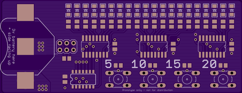
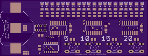
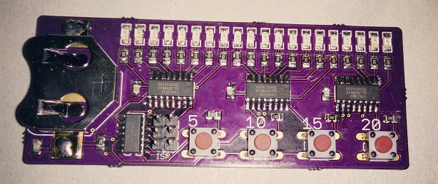
Timstock Slim has 4 coloured buttons with the number 5, 10, 15 or 20. This is the amount of minutes for the countdown. Now they only need to press the corresponding number which is connected to whatever task they need to do and the countdown begins. There is cognitive feedback via 20 LEDs to show the user how much relative time is left.
For those who yet haven't learned numbers the buttons are of different colour, which is used instead in the daily schedule or task list.

A Timstock has existed for quite a long time but it's bulky, boring and very expensive.
I'm making the next generation Timstock that will be as cheap as possible and not look like a handicap aid - and fully Open Source!

Having two sons who are autistic I've seen, and used, most available tools developed specifically for kids with their disabilities. Some are great, some are not, but they all have something in common: they are all horribly expensive!

I don't mind people making money - not at all - but overcharging just because you can is not something I can stand behind so several years ago I started to make my own tools and aids for the boys, and at the same time I was able to customise them to suit their specific needs.

My first version of my cheap Timstock was a free Android app that recycled a used/discarded phone into a free tool - instead of paying $200+ for a small box with four buttons and a handful of LEDs. This was well received and all the great feedback made all the hundreds of hours spent on precise design, usability and most importantly testing.

Now I'm making the next generation Timstock that will be as cheap as possible.


One issue with the original Timstock is that it's both bulky - and certainly look like a handicap aid... This is not always a good thing since autism is very much a hidden handicap and when the kids grow a bit older most of them try to hide their disabilities. This was why my Android app was so popular because nobody knew what they were using their phones for.

A bit more than a year ago I was asked if I knew about any old phones that was flat enough to be glued into a binder in order to simplify the usage for a young child who needed a Timstock in school for all activities - and the child kept misplacing the ordinary Timstock all the time. At this time I wondered if I could make a slimmer version, or perhaps a 2.0, and see how much I could push the costs?

After some tinkering at home I made a crude prototype and I decided to roll with it! My goal has always been to make it available for max $15 for the end user, thus making it available to everyone regardless of financial situation - quite the opposite to the many available tools on the market that normally runs from a few hundred dollars to way above $1000...

After writing about this on my blog I was contacted by one of the three original inventors in Sweden. He liked what I was doing and after asking him if there were any copyright issues he told me there were none, and that he really liked the idea of making it available to everyone - at low cost. It was also always my intention to make it Open Source - both hardware and software - because then people can customise it if needed or just make own pcb's. The only thing I don't allow is selling it for a profit - and I will chase anyone who tries to make money off it!

After a hiatus due to me being in an accident and I needed surgery I recently redesigned the whole board and changed many components and this is where I am today - just about to populate the 3:rd generation prototype.

The first prototype used WS2812b LEDs because you could use it to give excellent visual feedback with all the colours, but after testing I just could not motivate the current consumption so I reverted to single-colour LEDs instead and added shift registers to control them. It is based on an attiny84 and has an exposed ICSP header on the pcb for upgrades or customisation.

I hope the 3:rd generation prototype will perform well enough to make a final design of the layout, but this we'll soon find out!

My boys no longer need a Timstock to cope with the tasks in school e.g. but there are so many that do need one out there and they simply can't afford one so I have to finish what I've started.

To be continued...


For those of you who don't know what a Timstock is and how to use it? Here is a quick description.

The Timstock tool is a device for visually, and auditory, show the user progression of time, in 4 different increments/fixed times.

The most common configuration is 5, 10, 15, and 20 minutes, and each button has its own colour. When you press one of the buttons the time starts to count down until 0, when a visual and optional auditory alarm is displayed....

Read more »

  • 1 × ATTINY84 Microprocessors, Microcontrollers, DSPs / ARM, RISC-Based Microcontrollers
  • 3 × 74HC595D so16
  • 1 × Battery Clip 20 mm MPD (Memory Protection Devices) BK-883-TR
  • 4 × Tactile Switch B3F-10XX or similar
  • 4 × 0.1uF capacitor (changed from 15pF) 0805

View all 9 components

  • Minor update and next round in the comp...

    jens.andree09/22/2015 at 12:38 0 comments

    I have had very little time over for tinkering lately, partly due to the school start required more attention from my side than expected/wanted, but such is life I guess... There is nothing that I won't do for my boys and I'm used to meetings and discussions regarding their special needs.

    A recent discussion regarding shift registers vs. charlieplexing was interesting and it made me think that perhaps my chosen path was perhaps not the best way forward? I did three different attempts to change the design to a charlieplexed solution - but my routing skills are in no way on par with Dave Jones e.g. and with the important requirement that this should be possible to do at home vias etc are frowned upon and the layout became dodgy to say the least...

    The last attempt would've worked I guess but it required an increase in footprint of the pcb - which I've been trying to keep to a minimum from day one, and that's about how far I got with charlieplexing. This is not to say that I won't attack it again in the future but for now other things are more important.

    I also had planned a video which not only describes the functionality of Timstock Light in detail but also the methodology behind the tool, and more importantly how it's being used today by many kids. (and adults too)

    Sadly there wasn't enough time but as soon as I can I will finish, and post, this video because this is important for many - and cost should (read; must!) not be an obstacle for help.

    Thank you all for your kind comments and suggestions! I'm really grateful for this and all your likes and skulls! I've tried to thank all of you in one way or another, but you all are great and proof that together nothing's impossible!

  • New pcb's has arrived!

    jens.andree06/14/2015 at 10:05 0 comments

    Only a short update but the new pcb's from OSHPark has arrived and I shall hopefully be able to solder one of them tonight and start testing! :D

    This is exciting stuff since I can now - luck permitting - soon start to send out a bunch of units for usability testing in order to get the important feedback from the real users, with different age and needs.

    Summer has also finally(!!!) arrived in the south of Sweden and the BBQ is certainly being used as much as possible! Happy days! :)

  • Timstock Slim v0.93 pcb just shipped from OSH Park!

    jens.andree06/04/2015 at 20:35 0 comments

    This is just a short update but the revised v0.93 has just been depanelized and shipped by OSH Park, and now I have to wait for a couple of weeks until they arrive and I can populate a few new boards and send them away for usability testing!

    This is really exciting for me since I'm getting closer and closer to seeing this project becoming reality. I know there are many people who eagerly hoping for this to become reality, and at a cost which is perhaps 10 times less - or more! - than what's available today... That means that 10 or more children with need can now get the help they need for the same cost of one, and one that's way less bulky and looking like it came out of a hospital...

    My oldest son refused to use his old Timstock simply because it was so obviously a "handicap aid" - and this in a time when he discovered why and how he was different from the other kids, and although he knows there's nothing wrong with being autistic, he had a period - like most other kids - when he was uncomfortable with showing his handicap(s) from being autistic.

    Back then I developed a software version for Android and gave him a phone with the app Tim(mer) Stock (as I called it back then). That worked well and now no-one saw him using that old bulky tool any longer.

    Timstock Slim won't look like it's been handed out by a medical team, nor will it be bulky or hostile. It'll be whatever you want it to be since it can be put in an enclosure if you want, and this can look like whatever you want! There will also be a hole in the PCB on the next version after v0.93 so the user can have it around their neck with a lanyard, or hanging on a key chain or similar.

    Well, enough about that ;)

    There's a few changes to the code and I will also start performance testing as soon as all functional test-cases have passed, and the goal is to push the battery consumption as low as possible. It'll perhaps get a custom bootloader, but it will still be reflashable by all the users if someone want's to modify their Timstock Slim, or if someone has custom needs?!

    Open Source should mean Open in every way and that's why both the code and the schematic, and layout, will be well documented and explained for those who want to modify their own Timstock Slim - or make their own PCB!

    This will ensure that it'll be available in the 3:rd world as well, as long as someone has the capability to etch a pcb and flash the software. Money must not be a deciding factor if you can get help or not...

  • Testing, Murphys and expert help!

    jens.andree05/22/2015 at 23:03 0 comments

    When testing I noticed that my wiring of the 75HC595 shift registers was based on an old, and not that great, example I found some time ago and that it needed to be tweaked. Sadly due to the tight placement of the surface mounted components and their tracks I had to lift a couple of the legs of the shit registers and run bodge wires to rectify the situation - which would make the units unusable for usability testing... Well, shit happens and I instead rebuilt the new design on a breadbord to verify the changes. (This is why it's a must to keep a stock of older thru-hole components even if you only use surface mount stuff in the final work!)

    The two minor changes meant I had to ripup most of the board, but I started and although it went fine initially I quickly ran in to what I call "ugly routing" and I did a ripup and started again... and again... A few hours later the bottom ground plane stopped pouring and now I was both tired and frustrated because I really try to do all of my projects from scratch in order to learn and I rarely copy existing designs. Yes, I know I'm re-inventing the wheel every time but I want to learn something and not just copying!

    In the end I felt I was stuck with a mess and I really want to be able to offer the Timstock Slim to all of those who really need it out there in the world, and quality is way more important than my ego or me doing every little bit myself so I one again decided to ask the ever so kind user kizzap over att EEVBlog forum. Back when I started this project about two-ish years ago I got superb help from him, and a few others, and before this I didn't know what I was doing in Eagle. I'm a software developer with 20+ years in the telecom industry but my exposure to hardware has all been learned at home from tinkering and repair, but making my own circuits and such I only started with about three years ago so I still have a lot to learn.

    Anyhow, I sent the files to kizzap and asking him for some routing help and perhaps some pointers where I went wrong? I explained what I was trying to do and that I was a bit stuck at the moment...

    Today I got a message back from kizzap and not only had he looked at my routing - he had given the whole project an experts overhaul and done a really good job! I'm ever so grateful for the kind help he gave me and this is also why I'm writing about it here in detail because he really deserves credit for his contribution! Thank you kizzap! It means a lot to me getting the kind help, and it will help the project to reach its goal :)

    New boards have just been ordered from OSHPark - my favourite pcb supplier! Not the cheapest, certainly not the fastest with regards to shipping to Sweden, but they have the best preview order system IMHO and it makes it a lot easier for us who still have some experience to accumulate...

    The board is now 5 mm longer but the layout is less compact and the components are spaced better. kizzap also did some magic where the battery holder goes in order to make a better connection by removing copper around the contact surface, and thus making sure the contact will be good. He also moved the ISP header and soldering these new boards will be a lot simpler.

    The first units will be delivered to Barnhabiliteringen in Ystad, Sweden, for evaluation with autistic kids in various ages during the summer and feedback from them will be implemented and respun (hw) if needed. At some stage I'll need to make a custom enclosure as well in order for the Timstock Slim to be attached to a keyring or a lanyard around the neck. Perhaps it might be possible to do some conformal coating in order to protect the components and traces from shorting out but every little extra step will affect the cost, so an optional enclosure (which can be easily 3D-printed) will be the way to go. I don't know how many units I have to order for injection moulding starts to pay off, but that's not something I need to think about at this stage...

    I'm now glad I ran in to a bit of trouble...

    Read more »

  • Night-time soldering...

    jens.andree05/14/2015 at 00:29 2 comments

    I haven't had time to populate one of the latest PCB's that I received from OSH park a couple of days ago but apparently I wasn't tired tonight so I decided to give it a go. I often tinker at night when I can't sleep since it's quiet, the kids and the animals are sleeping and I know nothing's going to disturb me. I'm sure I'm not alone doing this at night ;)

    I haven't done any serious surface mount soldering in a while, and my layout is a bit fiddly, but it's only a prototype and I can correct anything that might be dodgy. Luckily all was fine and a quick test verified that all LEDs were working as well!

    Tomorrow I shall flash the bootloader on the ATTINY84 that's the brain of the tool but I shall be a bit more careful this time since last time I flashed a blank ATTINY85 I must've got a fuse wrong since it was impossible to flash it ever again - which was really annoying since it was soldered to the PCB that was prototype v2. I will use the Arduino IDE to flash via ISP this time since that's the planned way for the end-users to do it in case they want to update firmware or customise the tool for a specific need. (or just if they want to tinker!)

    Some of the resistors and one cap are a wee bit crooked, but this is a functional test of the design and not the final thing, and I had to hand solder all small components since the solder paste was just too damn cold to use initially. I did however solder the IC's with hot air and solder paste as the last step. In hindsight I should have done so with all components but it doesn't have to be pretty at this stage...

    (sorry for potato-cam. better pictures in the future...)

    One thing I must remember to the next version is to use surface mount tactile switches. I want the bottom side to be totally flat, and I certainly don't want anything sharp sticking out anywhere... The ISP header will never be populated in the finished product, just there to be added by the end-users if needed.

    I do hope my EE-fu has been strong and that my design works as intended because now I want to focus on the code from now on so I can begin usability testing in a month or so...

    Happy hacking!

  • Schematic and layout v0.91

    jens.andree05/10/2015 at 03:10 0 comments

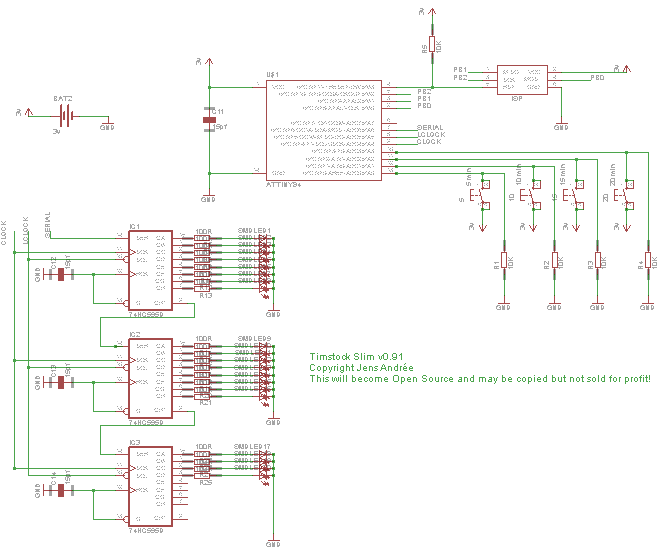
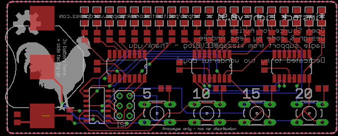
    The current prototype version is 0.91 and here is the current design.

    I have used Eagle CAD to make the project so far, and to keep it Open Source without software that costs money I'll stick with Eagle.

    The picture should give you an idea how it works. An attiny84 with three 74hc595 to control the leds, and four buttons to interface with the tool. A ISP header is exposed for upgrade or customisation by the end-user. All driven by a +3v battery.

    Here is the current layout. The second prototype was a lot smaller but due to the size of the 12 mm battery I had to make it larger, and to be honest - it couldn't be any smaller than it is now from a handling perspective... The previous version was using a smaller battery, but it had too short lifetime so a bigger one was needed. Did consider a rechargeable battery but that was adding a lot to the final cost, and mini-usb connectors tend to break off easily... Normal 12 mm button cell batteries are cheap and easily available.

    The leds will not be situated as high up on the pcb in the final version, but usability testing will determine the best location. Maybe it will be ok after all?

    There will also be a drilled hole for a lanyard or similar so it can be hung around the neck if needed, or wherever the user wants to hang it. There are no components on the back side so it can be easily glued onto a flat surface. (like inside a binder or on top of the daily schedule)

    I will make an optional slim plastic enclosure to it as well but it will add to the total cost and I don't know how much it costs to manufacture custom plastic parts? I really don't want to have to order a few thousand enclosures and be stuck with them later since I stride to make no money out of this, but that also means that I will have to try to spend as little money as possible up front. I can manufacture the pcb in small series which'll make it easier to forecast the demand, but custom injection moulded plastic parts are impossible to do that way unless you have a lot of money to burn...

    However, those who want to 3D-print their own enclosure can do so with the available 3D models.

    Problems are there to be solved and for now I focus on functionality and usability and worry about packaging later!

    When I'm functionally happy with this prototype and the necessary changes have been made I'll make the schematic and code available on GitHub. Then the chase for pushing the battery consumption will begin ;)

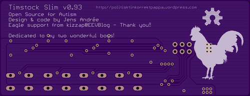
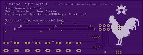
    When I started to make the first prototype my Eagle skills were less than great to say the least so I humbly asked for some guidance at the EEVBlog forum. The user kizzap amongst many was really helpful and gave me superb support with pointers in layout and routing! Since then the board has been respun two times and his parts have been redone, but as a big thank you for all the help in the beginning I've left a personal message to kizzap on the backside! :)

View all 6 project logs

Enjoy this project?

Share

Discussions

wiberg123 wrote 04/18/2017 at 22:19 point

Hey, how is this going? Really interested to see end product.

  Are you sure? yes | no

jens.andree wrote 09/24/2015 at 19:12 point

> My first time laying out a board with SMD parts.  Oops!  Here's Timstock Charlie
> SMD #2 using the correct SOIC footprint for the PIC.

k8ih - that's looking really slick!!!

I will set aside some Eagle time this weekend and have a play-around with your charlieplexed proposal! It is neither complicated nor hard to etch at home - if you can make simple vias. 

Have you omitted the resistors on purpose - i.e do you think they are redundant - or is it just as an example? The leds I'm currently using are rather picky on its resistor value depending on which colour I'm using... I've only played around with charlieplexing and the same leds before.

Many thanks!!! :D

Best Regards,
Jens

  Are you sure? yes | no

k8lh wrote 09/25/2015 at 23:04 point

Hi Jens.  Thanks for the nice comments.

Instead of current limiting resistors I'm relying on the cumulative ~100 ohm Rds(on) resistance of the MOSFETs in the PIC I/O pins.  

If you need to support different color LEDs in the matrix, perhaps you could use PWM to match brightness levels.  While adding resistors back into the circuit may seem easier, you may not have a lot of brightness to work with at the reduced LED duty cycles in a multiplexed display. 

I hope you get a chance to try this out.

Cheerful regards, Mike 

  Are you sure? yes | no

k8lh wrote 09/21/2015 at 23:55 point

Let us know when you post a video, please?  I'm anxious to see the LED sequences.  

I did a through-hole Charlieplexed version PCB layout (Timstock Charlie 3d) and now I see how laying out an SMD Charlieplexed version could be a nightmare.

  Are you sure? yes | no

jens.andree wrote 09/22/2015 at 11:34 point

I will! :) Sadly the school start for the boys required more attention than I'd wished for so I was unable to make a video for the Hackaday comp as well, but I've always put the kids first and myself way further down the line, and that's also partly why this project has taken so long to "finalise"... 
I also made an attempt to charlieplex Timstock Slim and it's neither pretty nor simple and would make it harder for someone to spin their own pcb so for now this is not a priority.

  Are you sure? yes | no

k8lh wrote 09/23/2015 at 19:03 point

Keep up the good work.  Looking forward to video.

If someone wanted to "spin their own pcb", it may not be as difficult as you or I thought.  Check out my first SMD attempt; Timstock Charlie SMD

  Are you sure? yes | no

jens.andree wrote 09/23/2015 at 21:51 point

Hmmm... Now that was an uncomplicated layout for sure! I must give this another go soon and compare the two solutions from a performance, and reliability point of view but less components is normally always a good thing - unless those times you forget something important... ;)

Many thanks k8lh (Mike)

  Are you sure? yes | no

k8lh wrote 09/24/2015 at 17:35 point

My first time laying out a board with SMD parts.  Oops!  Here's Timstock Charlie SMD #2 using the correct SOIC footprint for the PIC.

  Are you sure? yes | no

davedarko wrote 09/13/2015 at 05:33 point

Please don't jump on the charlie plexing thing - if just one LED breaks you'll have a problem finding it - just pull one out if you have a breadborded prototype. It's a neat trick to save IOs and your project is great, but mixing both seems not like a good idea. Get really bright LEDs and dimm them done with a big resistor, way safer. I worked on a 6×5 charlie plexed duo led matrix and the wiring in eagle was a challenge, but also fun and rewarding! - just nothing for a project like this.

  Are you sure? yes | no

jens.andree wrote 09/13/2015 at 19:57 point

Hi Dave and thanks for your comment!

Yes, this was my conclusion as well - after I abandoned the ws2812b implementation and played around with a few different multi-coloured leds... Crazy routing in Eagle and over-complicated design - which pretty much made it impossible, or at least very hard, for people to spin their own boards at home... Not to mention adapted versions... 

I have tried to keep it as simple as possible both with layout and the chosen components, and that it must be able to program with just Arduino IDE and a FTDI (ICSP) cable. 

It it also designed to be flat bottomed in order to be glued into a folder etc to be used during the day in combination with the daily schedule (with pictograms etc).

I'm currently making a video that shows how the Timstock Slim is being used in different scenarios. It's easy for us who already work with it to forget those who see it for the first time... There is a rather extensive process and methodology behind it which has been developed by experts in the field.

Best Regards,
Jens

  Are you sure? yes | no

davedarko wrote 09/13/2015 at 20:19 point

Great to hear! Looking forward to see the video :) 

  Are you sure? yes | no

petter.olofsson wrote 09/12/2015 at 08:56 point

Tjena Jens! I would like to agree with k8lh, that Charlie or Multiplexing would be a good idea. Not just for the price but for the batterylife, i'm guessing heavy usage might drain it in a day or two?(!) 

Multiplexing 20 leds to 5*4 would cut current used to 1/4. However this also reduces brightness, so it's depending on how bright they need to be.

Another powerthief is the series resistors, as they are using power without providing any service. It is possible to overdrive leds in short bursts, maybe 10-100 uS, without a series resistor. Requires some careful programming but i've tried this and only burned one led ;)

Moreover, this technique and Multiplexing should work great together!

Also, great project! Cheers!

  Are you sure? yes | no

jens.andree wrote 09/12/2015 at 14:15 point

Hej Petter!
The current power consumption is acceptable since the leds are only in use during the countdown, but the longer the battery life is - the better from an end-user perspective!

I shall cobble together a simple prototype with charlieplexed leds instead of the current shift register solution and see what benefits there are?

The leds are not required to be super bright - quite the opposite, but I have sourced a big collection of different leds and found ones who are suitable for the build - but of course "any" led will do. There is a mix of red, yellow and green leds for those who need the traditional support of a coloured "countdown" but it can also be populated with just one colour, but usability testing prefers the red-yellow-green solution.

If there are any negative effects of mixing different leds in charlieplexing will be shown since they require different value resistors... But that's why we prototype and see if the magic smoke appears or if it works as intended ;)

Thanks for all the comments and helpful tips!

Best Regards,
Jens

  Are you sure? yes | no

petter.olofsson wrote 09/12/2015 at 17:35 point

That's nice to hear, i have no idea how much the timstock would be used since i have never seen one :) 

You should have no problems mixing colors as long as you keep it in mind, you can probably group the same colors to the proper resistor. 

If you want to test how much battery you can save you should try driving the leds with pwm, since this would be what the leds would see in a charlieplex/multiplex array :)

Will be following to see how it goes!

  Are you sure? yes | no

k8lh wrote 09/13/2015 at 00:07 point

Hi, Jens.  

Would you like to explore using two-pin bi-color (red/green) LEDs in a Charlieplexed matrix where any individual LED can be modulated to light as red, green, or yellow?  It might allow for a single design that supports custom LED color requirements.   I've done this using PIC with a form of PWM called BAM (Bit Angle Modulation) and I would be happy to share my research and notes if you're interested.

Cheerful regards, Mike

  Are you sure? yes | no

jens.andree wrote 09/13/2015 at 19:49 point

k8lh (Mike)

A few iterations back I was using multi-coloured leds but this added very little value and only led to a more complicated design - and higher cost - so that was abandoned for the current design. Changing the colours of the leds led to confusion in usability testing, unless the different coloured leds were in fixed positions. The leds are already pwm in order to save battery but thanks for the tip! :)

Best Regards,
Jens

  Are you sure? yes | no

k8lh wrote 09/11/2015 at 13:00 point

jens.andree:  

a heart-warming project, Sir.  have you considered and/or tested a "Charlieplexed" display which would only require five (5) pins on the microcontroller while eliminating the three (3) 74HC595 ICs?

cheerful regards, mike

  Are you sure? yes | no

jens.andree wrote 09/11/2015 at 14:09 point

Hi Mike and thanks for you kind comment!
My first version used ws2812b but they were too costly with regards to power consumption, hence why I resorted to the setup I have today. (subject to change of course...)
I have used charlieplexing in other projects but one of the important features in this project I decided from start was adaptability, or simply the ease of making custom variants to suit specific needs or people. The currently chosen hardware and layout is simpler to program and to modify than a charlieplexed solution afaik and that's why I ran with it. It is also the reason why it's running an Atmel MC and it's all done with Eagle (free version) and Arduino IDE. This project is 100% open source with regards to both software and hardware, and if I can make it as easy as possible to modify then I believe that I can help as many as possible.
I can make it a lot cheaper by using less components and more complicated design, but then it'd be harder to make your own versions as well and this is the path I took to make it as simple as possible in all areas.
It is built to a cost, and as low as possible in order for it to be available to everyone, instead of most currently available "tools" that cost $300+ and beyond, but with simplicity in mind.
I think it's fundamentally wrong to make such big profits of selling handicap aids for kids and that's how this project started a few years ago - and now have evolved into a small and cheap tool that'll cost about as much as a pizza! If I somewhere down the line can make it cheaper, or if I for some reason end up with a profit somewhere, then the price will be adjusted accordingly because I'm doing this to help the kids and nothing else. 

Also I'm from a SW dev background and only got into HW hacking a few years ago so some of my choices are perhaps not the best ones, but I think the current setup for Timstock Slim should be easy enough to understand for anyone who has the ability to etch their own PCB's and solder a few components - if they for some reason can't order ready made ones or need to adapt it for a specific need.

There are a few companies that would like me to cease what I'm doing since it'll certainly cause them to lose business, but I'm not one to be easily budged... ;)

Best Regards,
Jens


  Are you sure? yes | no

k8lh wrote 09/11/2015 at 16:10 point

Hi Jens.  Please forgive me if it seemed I was criticizing your design.  I realize it's rather late in the development cycle to entertain suggestions and I apologize.

Still...  if you're interested...  please take a peek at a sample Arduino project (link below) which includes a simple Charlieplexing driver for 20 LEDs.  Perhaps it may come in handy in the future.

Link: http://forum.allaboutcircuits.com/threads/knight-rider-style-light-chaser.67803/#post-571226

Cheerful regards, Mike

  Are you sure? yes | no

jens.andree wrote 09/11/2015 at 17:25 point

I didn't take it as criticism and I'm sorry if I came across in that way. I'm instead more than happy to receive comments, criticism or suggestions - otherwise I wouldn't be here today!

I shall look at the example with the charlieplexing and perhaps the next iteration will be a total redesign?

Many thanks!!! 

  Are you sure? yes | no

Sophi Kravitz wrote 06/03/2015 at 15:37 point

Great project! following.

  Are you sure? yes | no

jens.andree wrote 06/03/2015 at 15:41 point

Thank you! :)
I'm about to post a new description for the project which Alex Rich kindly pointed out, and that should hopefully help others to find this. For us who have worked with this methodology for years and years it's common knowledge, but that is probably not the case internationally - thus why a better description and explanation is needed!

In the end of the day I hope to help as many as possible :)

  Are you sure? yes | no

Alex Rich wrote 05/23/2015 at 01:01 point

Jens, this is a great project.  Can I suggest putting a really short explanation at the top of your "description" section describing 1. what a Timstock is and 2. why you are designing a new one.  I had a hard time understanding the project until I read quite a bit down the page.  Good luck, I will be following!

  Are you sure? yes | no

jens.andree wrote 05/23/2015 at 01:06 point

Hi Alex and thanks for your kind comment! 
I didn't know how little space there was when I first decided to register the project so as I just wrote all the text on the fly I ran out of space and just continued in the next sections... But you are right - the project needs a brief description of what it is and why it's being made in the first section, and I'll sort this out ASAP.
For those who haven't heard about a Timstock I fully understand that this is a big mystery and not obvious at all.
Thank you for pointing this out and making it easier for others to understand what and why I'm doing this! :)


  Are you sure? yes | no

jens.andree wrote 05/12/2015 at 19:44 point

To all of you who are following me and/or giving me a skull - thank you so much! Instead of thanking each and one of you personally, and risk missing one of you, I'm saying it here instead to all of you :)

This is a project that's been brewing for quite a while now and should have been finished some time ago if I hadn't been in an accident which put me in a wheelchair for three years... (fractured pelvic with trapped nerves) I'm now finally mended and started walking again 6 weeks ago (!!!) and the creative flow has slowly begun to appear again, so I'm using this new energy to finish this project so it can finally help people around the world as intended.

Thank you!

  Are you sure? yes | no

Similar Projects

Does this project spark your interest?

Become a member to follow this project and never miss any updates