-
Minor update and next round in the comp...
09/22/2015 at 12:38 • 0 commentsI have had very little time over for tinkering lately, partly due to the school start required more attention from my side than expected/wanted, but such is life I guess... There is nothing that I won't do for my boys and I'm used to meetings and discussions regarding their special needs.
A recent discussion regarding shift registers vs. charlieplexing was interesting and it made me think that perhaps my chosen path was perhaps not the best way forward? I did three different attempts to change the design to a charlieplexed solution - but my routing skills are in no way on par with Dave Jones e.g. and with the important requirement that this should be possible to do at home vias etc are frowned upon and the layout became dodgy to say the least...
The last attempt would've worked I guess but it required an increase in footprint of the pcb - which I've been trying to keep to a minimum from day one, and that's about how far I got with charlieplexing. This is not to say that I won't attack it again in the future but for now other things are more important.
I also had planned a video which not only describes the functionality of Timstock Light in detail but also the methodology behind the tool, and more importantly how it's being used today by many kids. (and adults too)
Sadly there wasn't enough time but as soon as I can I will finish, and post, this video because this is important for many - and cost should (read; must!) not be an obstacle for help.
Thank you all for your kind comments and suggestions! I'm really grateful for this and all your likes and skulls! I've tried to thank all of you in one way or another, but you all are great and proof that together nothing's impossible!
-
New pcb's has arrived!
06/14/2015 at 10:05 • 0 commentsOnly a short update but the new pcb's from OSHPark has arrived and I shall hopefully be able to solder one of them tonight and start testing! :D
This is exciting stuff since I can now - luck permitting - soon start to send out a bunch of units for usability testing in order to get the important feedback from the real users, with different age and needs.
Summer has also finally(!!!) arrived in the south of Sweden and the BBQ is certainly being used as much as possible! Happy days! :)
-
Timstock Slim v0.93 pcb just shipped from OSH Park!
06/04/2015 at 20:35 • 0 commentsThis is just a short update but the revised v0.93 has just been depanelized and shipped by OSH Park, and now I have to wait for a couple of weeks until they arrive and I can populate a few new boards and send them away for usability testing!
![]()
![]()
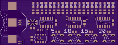
This is really exciting for me since I'm getting closer and closer to seeing this project becoming reality. I know there are many people who eagerly hoping for this to become reality, and at a cost which is perhaps 10 times less - or more! - than what's available today... That means that 10 or more children with need can now get the help they need for the same cost of one, and one that's way less bulky and looking like it came out of a hospital...
My oldest son refused to use his old Timstock simply because it was so obviously a "handicap aid" - and this in a time when he discovered why and how he was different from the other kids, and although he knows there's nothing wrong with being autistic, he had a period - like most other kids - when he was uncomfortable with showing his handicap(s) from being autistic.
Back then I developed a software version for Android and gave him a phone with the app Tim(mer) Stock (as I called it back then). That worked well and now no-one saw him using that old bulky tool any longer.
Timstock Slim won't look like it's been handed out by a medical team, nor will it be bulky or hostile. It'll be whatever you want it to be since it can be put in an enclosure if you want, and this can look like whatever you want! There will also be a hole in the PCB on the next version after v0.93 so the user can have it around their neck with a lanyard, or hanging on a key chain or similar.
Well, enough about that ;)
There's a few changes to the code and I will also start performance testing as soon as all functional test-cases have passed, and the goal is to push the battery consumption as low as possible. It'll perhaps get a custom bootloader, but it will still be reflashable by all the users if someone want's to modify their Timstock Slim, or if someone has custom needs?!
Open Source should mean Open in every way and that's why both the code and the schematic, and layout, will be well documented and explained for those who want to modify their own Timstock Slim - or make their own PCB!
This will ensure that it'll be available in the 3:rd world as well, as long as someone has the capability to etch a pcb and flash the software. Money must not be a deciding factor if you can get help or not...
-
Testing, Murphys and expert help!
05/22/2015 at 23:03 • 0 commentsWhen testing I noticed that my wiring of the 75HC595 shift registers was based on an old, and not that great, example I found some time ago and that it needed to be tweaked. Sadly due to the tight placement of the surface mounted components and their tracks I had to lift a couple of the legs of the shit registers and run bodge wires to rectify the situation - which would make the units unusable for usability testing... Well, shit happens and I instead rebuilt the new design on a breadbord to verify the changes. (This is why it's a must to keep a stock of older thru-hole components even if you only use surface mount stuff in the final work!)
The two minor changes meant I had to ripup most of the board, but I started and although it went fine initially I quickly ran in to what I call "ugly routing" and I did a ripup and started again... and again... A few hours later the bottom ground plane stopped pouring and now I was both tired and frustrated because I really try to do all of my projects from scratch in order to learn and I rarely copy existing designs. Yes, I know I'm re-inventing the wheel every time but I want to learn something and not just copying!
In the end I felt I was stuck with a mess and I really want to be able to offer the Timstock Slim to all of those who really need it out there in the world, and quality is way more important than my ego or me doing every little bit myself so I one again decided to ask the ever so kind user kizzap over att EEVBlog forum. Back when I started this project about two-ish years ago I got superb help from him, and a few others, and before this I didn't know what I was doing in Eagle. I'm a software developer with 20+ years in the telecom industry but my exposure to hardware has all been learned at home from tinkering and repair, but making my own circuits and such I only started with about three years ago so I still have a lot to learn.
Anyhow, I sent the files to kizzap and asking him for some routing help and perhaps some pointers where I went wrong? I explained what I was trying to do and that I was a bit stuck at the moment...
Today I got a message back from kizzap and not only had he looked at my routing - he had given the whole project an experts overhaul and done a really good job! I'm ever so grateful for the kind help he gave me and this is also why I'm writing about it here in detail because he really deserves credit for his contribution! Thank you kizzap! It means a lot to me getting the kind help, and it will help the project to reach its goal :)
New boards have just been ordered from OSHPark - my favourite pcb supplier! Not the cheapest, certainly not the fastest with regards to shipping to Sweden, but they have the best preview order system IMHO and it makes it a lot easier for us who still have some experience to accumulate...
![]()
![]()
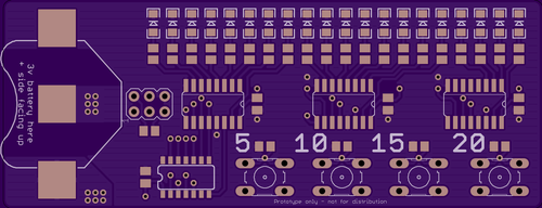
The board is now 5 mm longer but the layout is less compact and the components are spaced better. kizzap also did some magic where the battery holder goes in order to make a better connection by removing copper around the contact surface, and thus making sure the contact will be good. He also moved the ISP header and soldering these new boards will be a lot simpler.
The first units will be delivered to Barnhabiliteringen in Ystad, Sweden, for evaluation with autistic kids in various ages during the summer and feedback from them will be implemented and respun (hw) if needed. At some stage I'll need to make a custom enclosure as well in order for the Timstock Slim to be attached to a keyring or a lanyard around the neck. Perhaps it might be possible to do some conformal coating in order to protect the components and traces from shorting out but every little extra step will affect the cost, so an optional enclosure (which can be easily 3D-printed) will be the way to go. I don't know how many units I have to order for injection moulding starts to pay off, but that's not something I need to think about at this stage...
I'm now glad I ran in to a bit of trouble with Eagle because the overhaul kizzap did for me has put the project in a much better state with regards to quality - and that it has been reviewed by an expert certainly feels great for me as I keep pushing on!
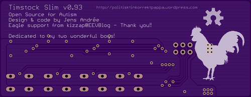
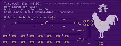
p.s The cock on the bottom silk screen is my first Brahma cock that I hatched when I bought my old farm 8 years ago and he kinda became the mascot of where we live! He's now sadly no longer around since Mr. fox got him a few years ago, but his offspring are running around free here and chickens are part of our life ever since. Great responsibility for two boys as well since there are eggs to collect and food and water to be catered for.
-
Night-time soldering...
05/14/2015 at 00:29 • 2 commentsI haven't had time to populate one of the latest PCB's that I received from OSH park a couple of days ago but apparently I wasn't tired tonight so I decided to give it a go. I often tinker at night when I can't sleep since it's quiet, the kids and the animals are sleeping and I know nothing's going to disturb me. I'm sure I'm not alone doing this at night ;)
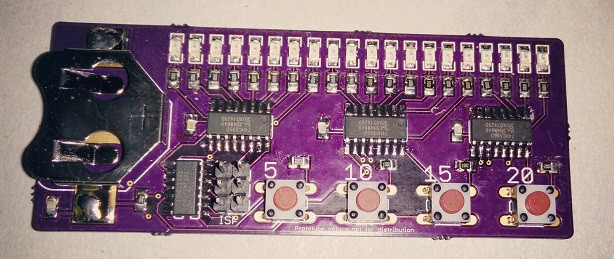
I haven't done any serious surface mount soldering in a while, and my layout is a bit fiddly, but it's only a prototype and I can correct anything that might be dodgy. Luckily all was fine and a quick test verified that all LEDs were working as well!
Tomorrow I shall flash the bootloader on the ATTINY84 that's the brain of the tool but I shall be a bit more careful this time since last time I flashed a blank ATTINY85 I must've got a fuse wrong since it was impossible to flash it ever again - which was really annoying since it was soldered to the PCB that was prototype v2. I will use the Arduino IDE to flash via ISP this time since that's the planned way for the end-users to do it in case they want to update firmware or customise the tool for a specific need. (or just if they want to tinker!)
Some of the resistors and one cap are a wee bit crooked, but this is a functional test of the design and not the final thing, and I had to hand solder all small components since the solder paste was just too damn cold to use initially. I did however solder the IC's with hot air and solder paste as the last step. In hindsight I should have done so with all components but it doesn't have to be pretty at this stage...
![]()
(sorry for potato-cam. better pictures in the future...)
One thing I must remember to the next version is to use surface mount tactile switches. I want the bottom side to be totally flat, and I certainly don't want anything sharp sticking out anywhere... The ISP header will never be populated in the finished product, just there to be added by the end-users if needed.
I do hope my EE-fu has been strong and that my design works as intended because now I want to focus on the code from now on so I can begin usability testing in a month or so...
Happy hacking!
-
Schematic and layout v0.91
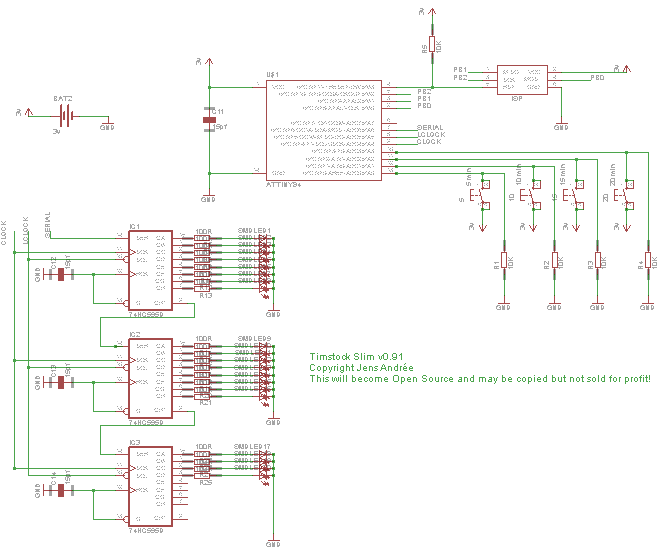
05/10/2015 at 03:10 • 0 commentsThe current prototype version is 0.91 and here is the current design.
I have used Eagle CAD to make the project so far, and to keep it Open Source without software that costs money I'll stick with Eagle.
The picture should give you an idea how it works. An attiny84 with three 74hc595 to control the leds, and four buttons to interface with the tool. A ISP header is exposed for upgrade or customisation by the end-user. All driven by a +3v battery.
![]()
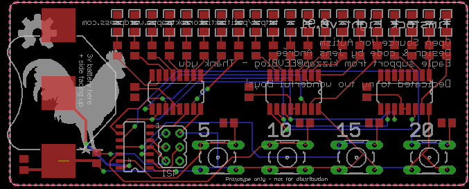
Here is the current layout. The second prototype was a lot smaller but due to the size of the 12 mm battery I had to make it larger, and to be honest - it couldn't be any smaller than it is now from a handling perspective... The previous version was using a smaller battery, but it had too short lifetime so a bigger one was needed. Did consider a rechargeable battery but that was adding a lot to the final cost, and mini-usb connectors tend to break off easily... Normal 12 mm button cell batteries are cheap and easily available.
![]()
The leds will not be situated as high up on the pcb in the final version, but usability testing will determine the best location. Maybe it will be ok after all?
There will also be a drilled hole for a lanyard or similar so it can be hung around the neck if needed, or wherever the user wants to hang it. There are no components on the back side so it can be easily glued onto a flat surface. (like inside a binder or on top of the daily schedule)
I will make an optional slim plastic enclosure to it as well but it will add to the total cost and I don't know how much it costs to manufacture custom plastic parts? I really don't want to have to order a few thousand enclosures and be stuck with them later since I stride to make no money out of this, but that also means that I will have to try to spend as little money as possible up front. I can manufacture the pcb in small series which'll make it easier to forecast the demand, but custom injection moulded plastic parts are impossible to do that way unless you have a lot of money to burn...
However, those who want to 3D-print their own enclosure can do so with the available 3D models.
Problems are there to be solved and for now I focus on functionality and usability and worry about packaging later!
When I'm functionally happy with this prototype and the necessary changes have been made I'll make the schematic and code available on GitHub. Then the chase for pushing the battery consumption will begin ;)
When I started to make the first prototype my Eagle skills were less than great to say the least so I humbly asked for some guidance at the EEVBlog forum. The user kizzap amongst many was really helpful and gave me superb support with pointers in layout and routing! Since then the board has been respun two times and his parts have been redone, but as a big thank you for all the help in the beginning I've left a personal message to kizzap on the backside! :)
Timstock Slim - a tool for the autistic
Timstock Slim is a simple tool that helps autistic children to tell them when a task is finished or when it's time for something to happen!
 jens.andree