drewrisinger
-
Updates Coming Soon
07/12/2015 at 20:43 • 1 commentI just got back from vacation, and am looking at ways to improve this project and its documentation on this page. Currently on the list:
- Posting pictures of finished boards
- Adding build instructions
- Getting feedback on ways to improve the boards to make them easier to use/more useful.
- I will also post links to the OSH Park site where you can buy your own boards to put together, as well as a digikey BOM (or maybe just Excel BOM) premade with all the parts you'll need to create one of these.
If you have anything you'd like to see from this project, let me know and I'll try to document it/incorporate it.
-
Boards Built
06/18/2015 at 02:30 • 3 commentsWell, today I finished testing and building both versions of the board (using both the ESP-01 and ESP-03 chipset). I managed to do both with the default tip on a WESD51. Ugh, that tip is so big when I'm trying to do SMD soldering. Needless to say, a new tip is on the way.
The ESP-01 version works perfectly, no modifications needed. I did make a rookie mistake, however. I was originally trying to blink an LED off of pins 12 and 14. It took me about 15 minutes to realize that those pins aren't available because I'm using an ESP-01, which only breaks out a few pins. To clarify this issue, I'm going to make some changes to the board next time to mark which pins correspond to the ESP-01 variant.
The ESP-03 version needed a bit of work. I initially saw it boot fine, but it seemed impossible to get it to restart. I found online that supposedly the CH_PD pin needed to be connected to Vcc, which I hadn't done. When I tried doing that, I couldn't get the chip to reset using the method used for the ESP-01. After a little experimentation, I found that I could reset the chip (with the fewest amount of changes and maximum compatibility) by tying together the RESET and CH_PD lines. A little bit of soldering work later, and the board now works perfectly.
So after the first trial run, my list of changes for future are:
- Tie together CH_PD and RST on the board.
- Label which breadboard pins correspond to ESP-01 and ESP-03.
- Figure out some easier way to space the reset & program buttons. They work, but are hard to push if you have large fingers
- Do some testing to see if I need the 3.3V/>4.2V switch at all. Would be nice if I could eliminate it, which would shrink the board and drive down cost by almost $1.
- Switch Resistor/Capacitor pads from wide version to normal version. For initial production I used the wide version, because it's always easier to go bigger than to shrink (see my DrDAC project for proof). But this makes it harder to get the SMDs on straight, and they'll look nicer if all aligned.
Random last thought: If you're tinning SMD pads, ONLY TIN 1/2. Otherwise you'll end up with too much solder on, and then you can't melt both pads, and then the package ends up at a funky angle vertically, and not flat to the board. So just tin one.
I'll post pictures later...
-
Layout v1.5 Complete
05/26/2015 at 03:53 • 0 commentsWell, after fixing the ground plane issue, I decided to make major revisions to the layout and labeling of my board, creating a higher-quality, more useful board in the process.
First, an obligatory changelog:
- Remove ground plane under antenna
- This was previously addressed in my last post. But here it's actually complete!
- Change size of board to 1.0"W by 1.6"L.
- This was to accommodate the full length of the ESP-01 board, which would previously just out over the edge of the board. I decided that this would add robustness for a marginal loss of size and cost (the cost is an extra $0.30 per board at OSH Park).
- Change to layout of components.
- This was partly in response to the changed board size, but also just to make it easier to solder and visualize the path of everything on the board. Additionally, this meant fewer vias, and a cleaner look overall, with more open space.
- This also allowed more space for...
- Mounting Holes. For number 2 standard sized US screws (0.090" hole).
- I think this will allow my board to be more useful in a variety of different projects, and allow for permanent standalone installations.
- Label switches with their function, and S3 with the direction for each input voltage level
- Labels for ESP-01 Headers
- Clearer Logo Graphics.
- Cause as much as I love pixel art, I love for my work to be at a higher quality even more.
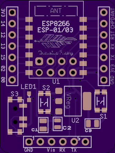
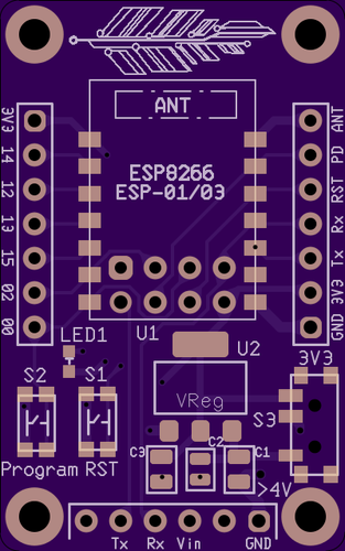
Renders![]() ^Top
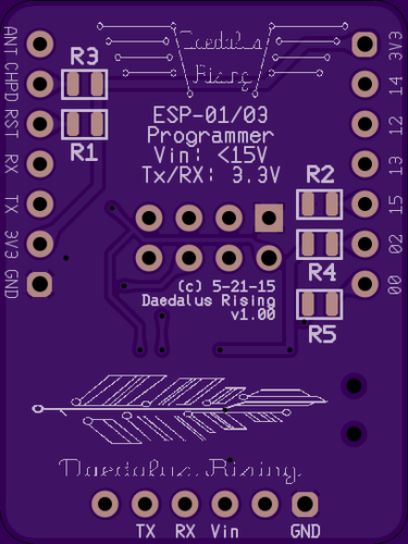
^Top![]() ^Bottom
^Bottom - Remove ground plane under antenna
-
Oops... Ground plane problems
05/23/2015 at 22:58 • 0 commentsWell, I just realized today that the ground plane of my board extends under the antenna of both the ESP-01 & ESP-03 that my board is targeting.
As someone with RF experience will tell you (which includes myself, believe it or not considering this dumb mistake), a ground plane will reflect the RF energy from the antenna (see the Wikipedia article on ground planes). Which is great if you're trying to receive the signal. If you're trying to transmit the signal, it won't be able to go through the ground plane, which can wreak havoc when you don't know where your receiving WiFi antenna is.
So, I'm currently in the process of redesigning the board to counter this problem. Since I needed to make this change, I decided to fix some of my other qualms I had about the board (such as spacing of pin headers, layout, grouping switches, etc), and make the layout more uniform. I'm also planning on adding mounting holes, since I'm looking at expanding the size of the board to accommodate the full length of the ESP-01 board (on the previous version, it would overhang the edge of the board, which could possibly leave it unprotected depending on the situation.
I'm also adding labels to make the operation of the board more transparent.
-
Board Rev 1.0
05/23/2015 at 03:20 • 0 commentsSo the boards have been sent out to OSH Park for manufacturing (as of 2am last night/this morning). Current size is around 1.36"L x 1"W, which might be able to be shrunk a little more in future revisions.
![]()
![]()
Now that I have a 1.0 version, I figured it was time to actually put the project out there for feedback and educational purposes. I will detail those aspects in separate posts, but I just want to leave the board information here in this post for now.
The board layout (done in Ultiboard because that's what I am familiar with and had available) can be found in my Github Repository. The board can also be found at OSH Park.
Components:Qty Ref# Part # Description Price (ea) 1 U1 ESP8266 ESP-01 or ESP-03 Microcontroller $4 1 U2 LD1117AS33 3.3V 1A Step Down Regulator. (SOT33) $0.68 1 C2 GRM188R7E104KA01D 0.1 uF Ceramic Capacitor. (0603) $0.10 2 C1, C3 GRM219R60J106KE19D 10uF Ceramic Capacitor. (0805) $0.15 4 R1, R2, R3, R4 ERJ-3GEYJ103V 10k 1/10W SMD Resistor. (0603) $0.10 1 R5 ERJ-3GEYJ102V 1k 1/10W SMD Resistor. (0603) $0.10 1 LED1 LTST-C190KFKT Orange SMD LED. (0603) $0.26 2 S1, S2 KMR221NG LFS MIni Tactile SPST Switch. NO, 0.05A 32V. $0.51 1 S3 PCM12SMTR Slide SPDT Swtich. 300mA 6V. $0.81 1 J1, J2, J3 4-103741-0 Breakaway .1" Headers. 40 position (break off 2x 7 pos and 1x 6) $1.94
ESP-01 & ESP-03 Breakout
Breakout board for ESP8266 ESP-01 & 03 modules
 ^Top
^Top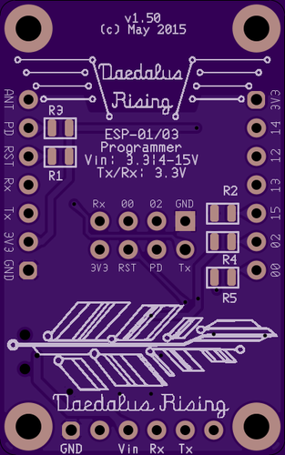 ^Bottom