Rui Rex
-
OBD2 support
11/17/2015 at 17:15 • 0 commentsMy initial thoughts included an interface with the car's OBD2 interface but I though it would be a bit hard to get the protocol right.
But this changed a bit as I found that some people were already doing this on arduinos (OBDuino, there's a lot of info on this) and the opengauge project (https://github.com/magister54/opengauge) so maybe there's hope on this chapter :)
I'll check if I can convert this to pure C code and use it on this module.
For the electrical part I was thinking of using a cheap OBD2 bluetooth dongle and removing the bluetooth module so I could interface the UART pins directly from the Stellaris.
My Audi A4 doesn't have a CAN interface but instead K-LINE (ISO 9141-2 protocol) at about 10kbps so the update rate isn't so good. It will have to do...
More on this latter...
-
Improve speed part 2
11/17/2015 at 16:08 • 0 commentsHere are the videos of the speed improvement from 16 to 25Mhz SPI speed:
@ 16Mhz
@25Mhz
It's not very noticeable as the speeds start to match the phone's camera fps. So we'll look at the counters instead.
The counters on the display show the value of the timer 1 running at 80Mhz.It counts to ~102M on 16Mhz and to ~72M on the 25Mhz for a set o 10 frames (16 bit mode). There's a bug somewhere because I clear the timer value from one iteration to the other but it keeps the value. So I added an extra line with the difference on the bottom.
This results in a time reduction from 126ms to 90ms for a single full frame write. Equivalent to about 11fps. Not super smooth but I won't be running video on this :)
More than enough considering the SPI interface and the "big" screen resolution.
I could improve even more by using the SPI FIFO but doesn't seem to get a lot more than this and would require a lot of SW changes.
-
Improve speed
08/26/2015 at 14:54 • 0 commentsI'm trying to improve the graphics speed. I saw some guys using a 16 bit mode on the SPI interface on a arduino setup and investigated a bit and found the configuration for the LM4F SPI bus to set it to 16 bit. Made a quick test and the gain is great! It's easily seen in the videos.
For testing purpose I've added a few screen fills on the startup sequence, black/white/black...
8 bit:
16 bit:
I'll make some measurements to see how much it improves but it's visibly faster.
Now I have to solve some issues on the software as the images are arranged in 8 bits and making a direct assignment to 16 bits won't work. This is not a problem on black and white as they are all zeroes or all ones but on diferent colors that's not the case. I made some preliminary tests but didn't work. Have to work a bit more on this.
Edit 1: Color issues solved. So now images also run on 16bit mode.
Edit 2: Even faster speed as I reduced the cable length and was able to run the SPI at the max. allowed speed on the Stellaris of 25Mhz. With the longer cable setting I can only go up to 16Mhz. Will post a video of the differences.
Now, by my calculations, one full frame takes about 70ms. Fast enough... :)
-
2.8" TFT arrived!
07/23/2015 at 13:08 • 0 commentsFinally the 2.8" TFT arrived!
Now I'll test it and then prepare it to the final assembly. I'll remove the SD card slot as I did with one of the 2.4" so that it doesn't need so much depth on the cluster plastic to be cut off.
Also I'll have to cut the top of the PCB where the SD-card connections are because of the high-beam warning light position. Hopefully it fits...
Here are some photos :)

Edit:
And now it working! Seems a bit dimmer, I'll have to make a test but if the number of backlight LEDs is the same it's expected. Also, I'm still not driving the LEDs full power yet. If I recall datasheet says If=60mA (=3 LEDs ?). I'll try it latter.
Size comparison:
-
Location, location, location
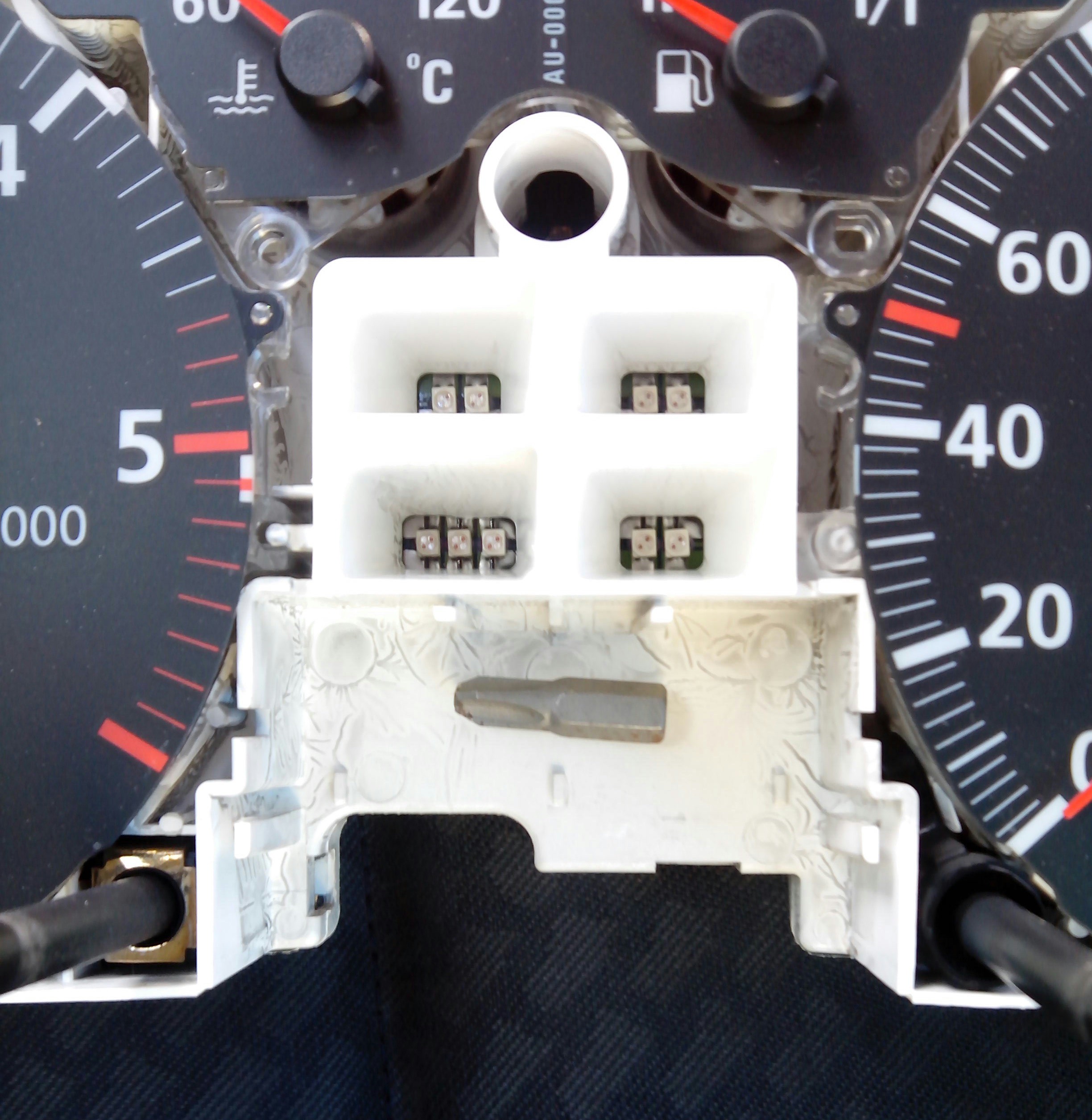
06/16/2015 at 15:46 • 0 commentsI've removed the cluster to see if there was enough room for the display.
On the bottom part there's no problem whatsoever. On the top there's the warning lights. The white plastic goes up to the front covers that have the drawings. I'll have to cut the plastic a few mm down so that the display can fit.
I'm also thinking on connecting other leds that will be placed somewhere else to prevent missing a warning in case something goes wrong with the microcontroller.
I placed a tool bit so I could later measure the distances without having to open it again. Have to measure the bit though :)
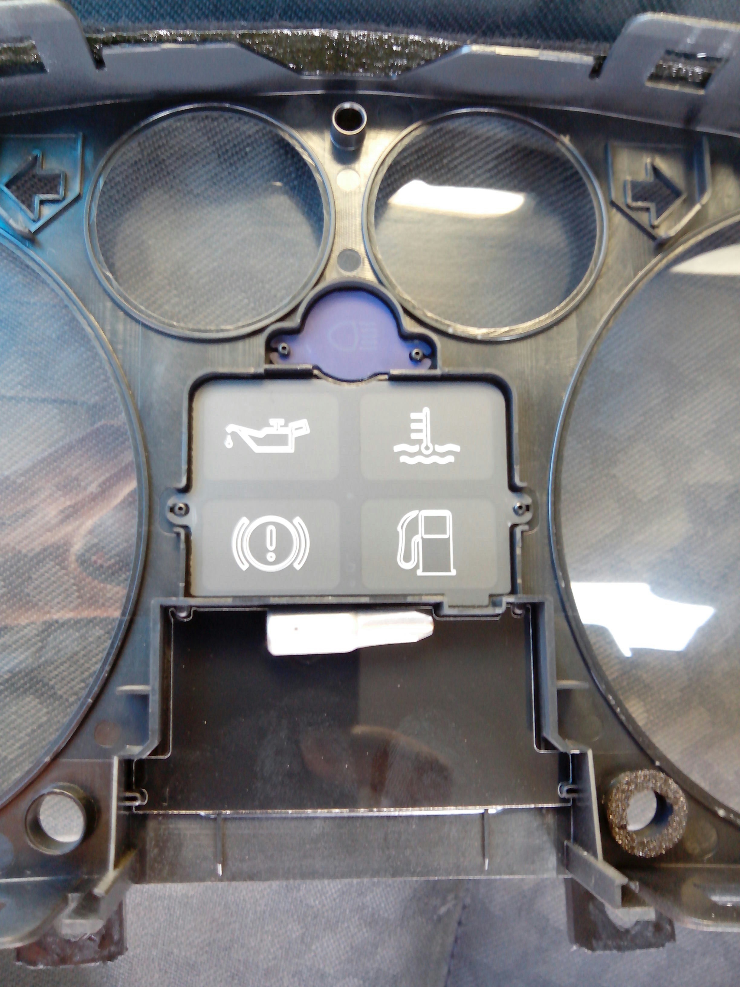
On the front cover I'll have to remove the plastic that contain the drawings and cut the remaining frame below it.
Goal: not to mess the looks of the panel! Cut very carefully!
-
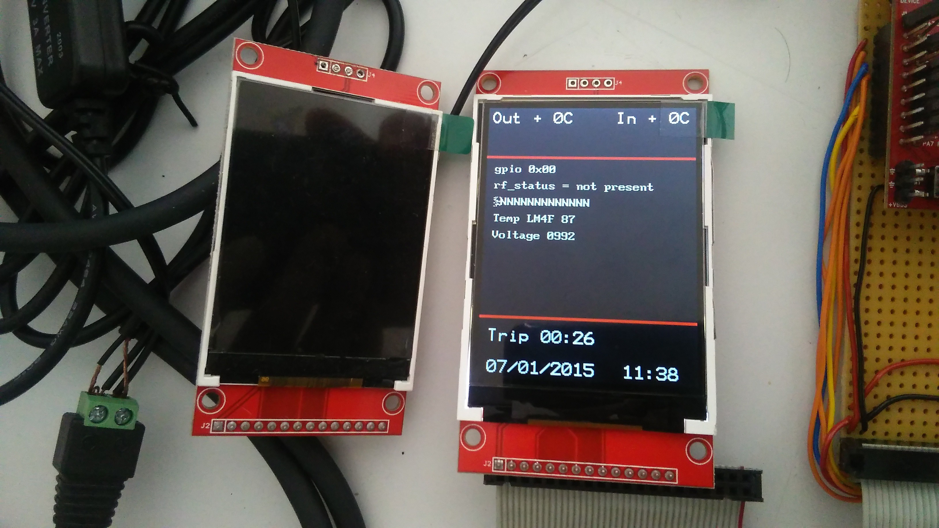
Some footage
06/15/2015 at 15:51 • 0 commentsExamples of the board booting up.
This board doens't have the temperature sensors connected so they display 0ºC...
-
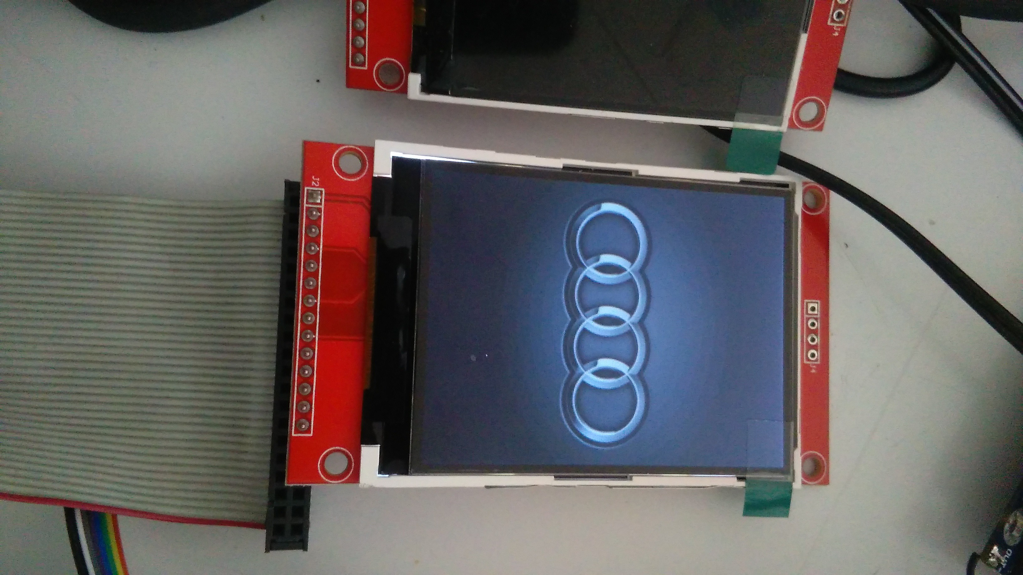
Making a boot logo
06/15/2015 at 14:16 • 0 commentsWhen I turn the key on I want it to boot with the Audi logo :) This can be changed for whatever I want.
I searched for a picture online, then edited it to remove unnecessary blank space (I'm not using any compression on the images to improve speed), scale it to fit on the 320x240 display and then convert it to 16bit RGB565 format.
This is the format used by the display and it's easier to have the picture saved already in the correct format.
First I thought on using an SD-card to save the pictures, but with the vibration of the car I could have to solder some wires to avoid bad connections. But I managed to cut the image a bit and it fits on the micro's flash without occupying much space. It's also faster as I don't need to read it from the SD card and then write it to the display.
-
First steps
06/15/2015 at 14:05 • 0 commentsThe first trials were made using jumper wires connectin the stellaris launchpad to the 2.4" TFT display.
Currently I'm making a boosterpack from perfurated PCB to prevent wires from disconnecting. Ideally I should design a proper PCB to prevent all sorts of bad things from happening, but that's a future issue.
Also, I found on Ebay what I've wanted from day one, a 2.8" version of the display! This will allow to fit the display perfectly on the cluster and not have to make a mask for the blank spaces between the TFT and the opened area. I'm going to buy it and later post the changes.
Onboard Stellaris car computer
Audi A4 onboard computer based on the Stellaris launchpad board.