0%
0%
Star Wars training droid
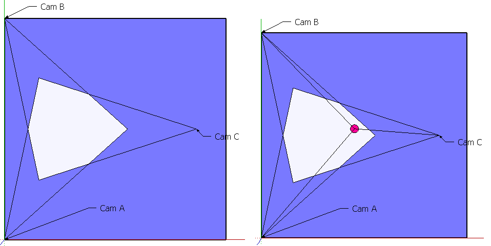
Flying training droid that interacts with its opponent.
 Roeland54
Become a Hackaday.io member
Already have an account? Log in.
Just one more thing
To make the experience fit your profile, pick a username and tell us what interests you.
Pick an awesome username
hackaday.io/
Your profile's URL: hackaday.io/username. Max 25 alphanumeric characters.
Pick a few interests
Projects that share your interests
People that share your interests


 Duane Degn
 Yohan Hadji
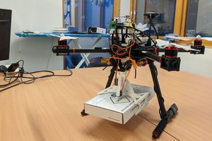
 Fin Mead
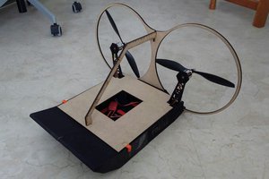
 Juan Sandubete
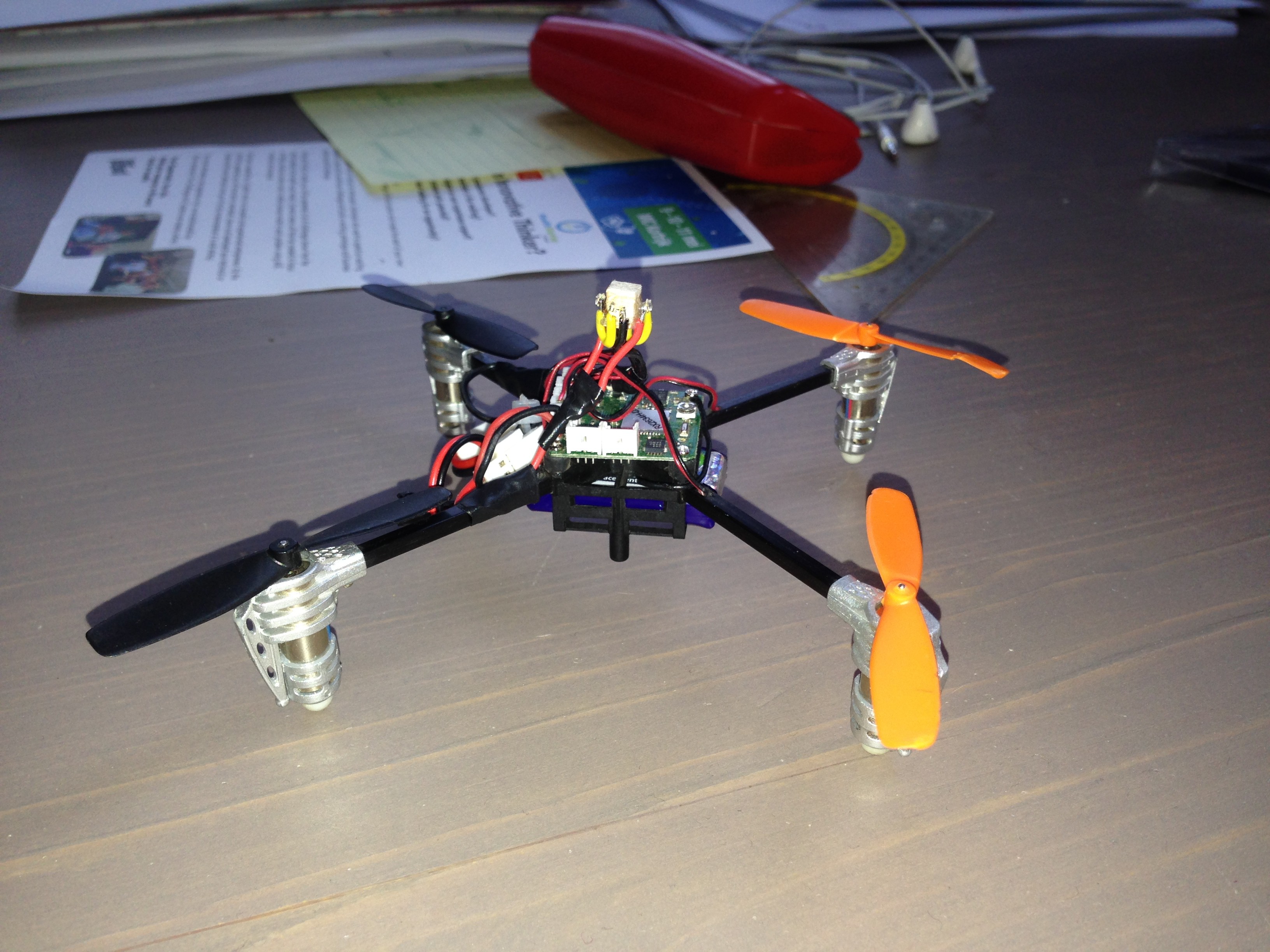
Make it round... *easy enough*
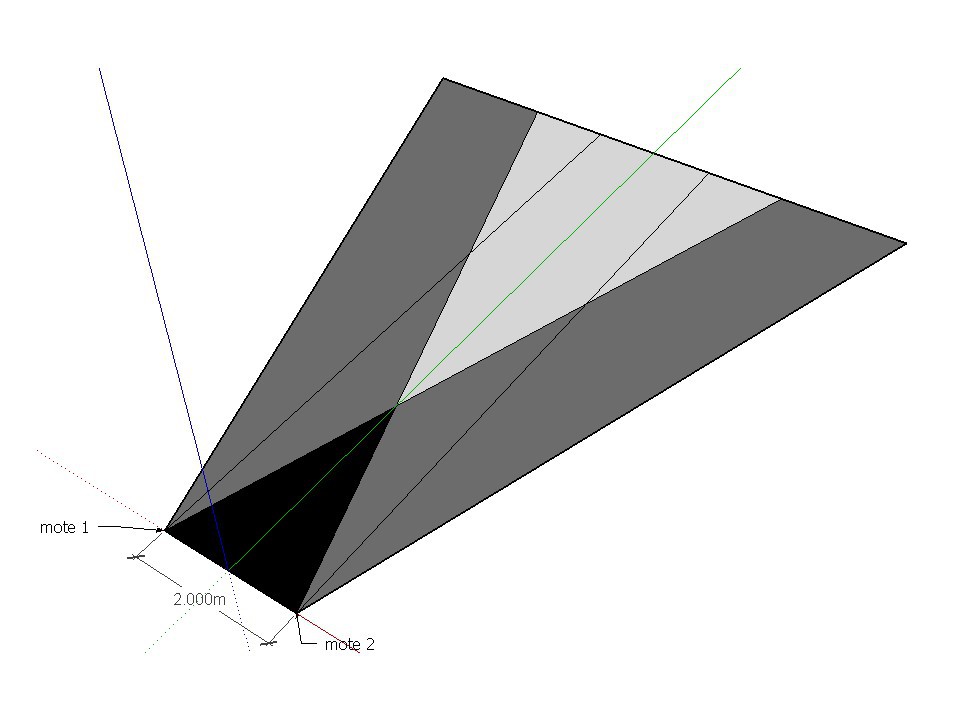
Make it shoot things. (more difficult... I would suggest CO2 and airsoft pellets.) Looks like you are getting the targeting down just fine.
------
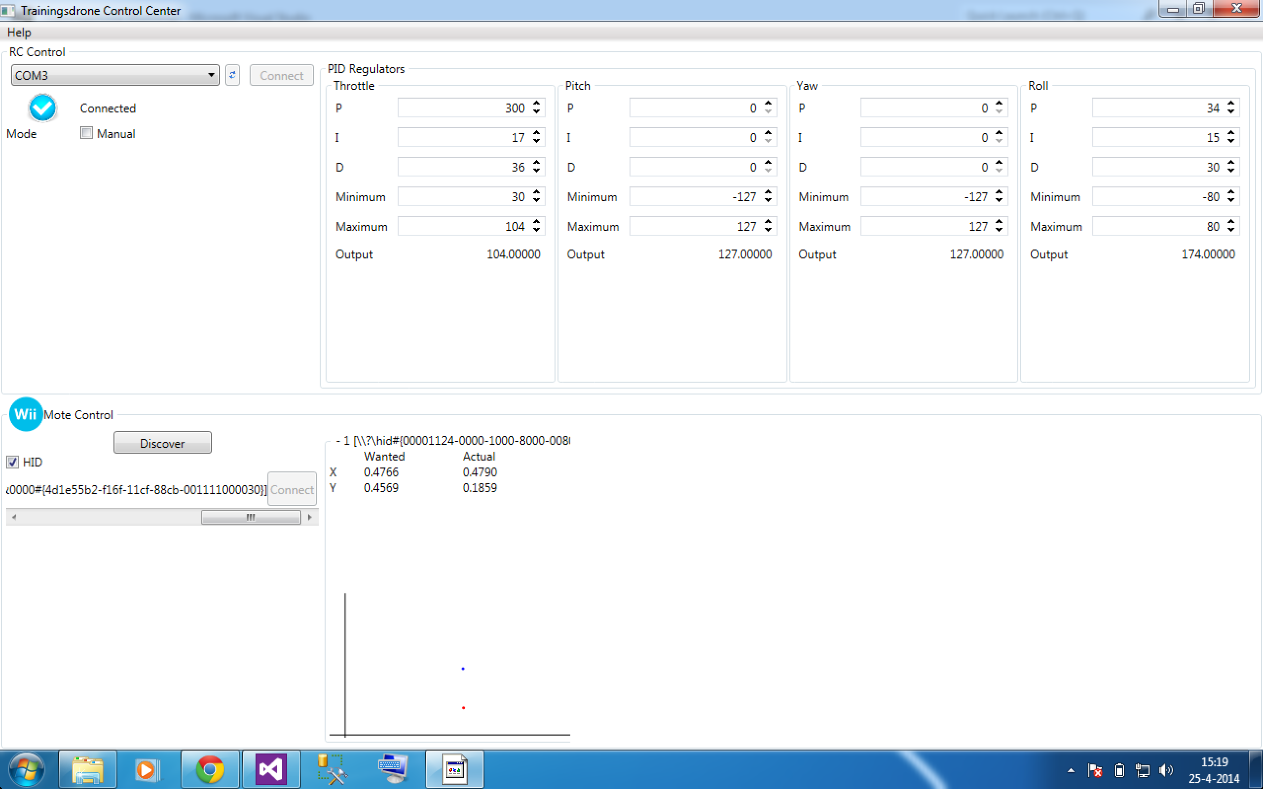
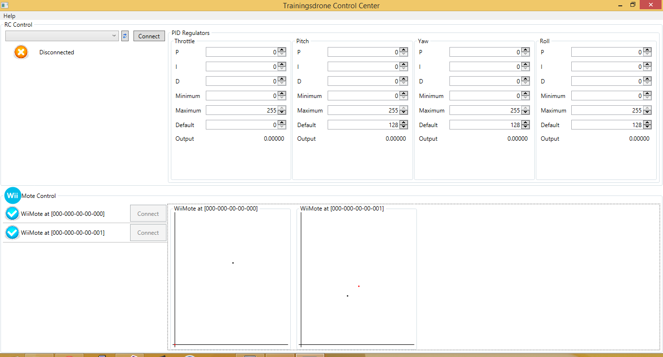
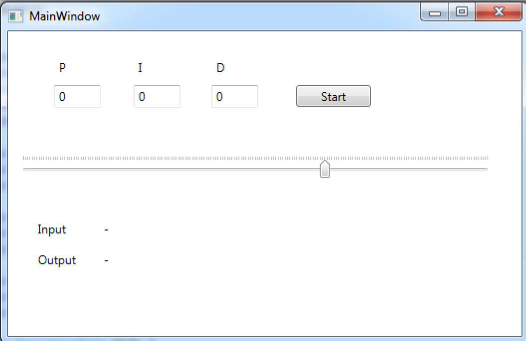
Also use a raspberry pi to move the software to onboard.
The pellets though, I have my heart set on airsoft pellets.
Almost forgot. Add in either a ultrasonic rangefinder or laser rangefinder for additional accuracy.