-
1Step 1
Let's Build a Phono Stage
These instructions will guide you from beginning to end. If anything is unclear, let me know in the comments section.
You will be able to build the Muffsy Phono Preamp, even if you've never soldered anything before in your life.
Now let's start with some basics:
Before You Begin
- Soldering the Muffsy Phono Preamp PP-3 will take about one and a half hour.
- Make sure you have enough time, and an environment without distractions. Don't stress, just enjoy building.
- Take the time to read and understand the instructions.
- Make sure you understand each step. If not, read again or ask a question in the comments section.
- Notice that many components must be oriented a certain way.
- Clicking on a picture will bring up a high resolution version. Use this to make sure your components are placed right.
How to Solder
If you're just starting out soldering, or if you need an update on how to solder,SparkFun has a great tutorial for soldering through-hole components.
If you have never soldered before, I strongly recommend these two videos from EEVBlog:
-
2Step 2
Info about the Kit and Instructions Overview
The Muffsy Phono Preamp PP-3 comes as a kit that you can order on Tindie, that includes everything needed to build a complete phono stage.
To make it do anything useful, you need to complete it with a power supply, cables and connectors, and an enclosure.
Make sure that you have all the components, depending on which option you chose when ordering the kit. All required components are listed in the bill of materials.
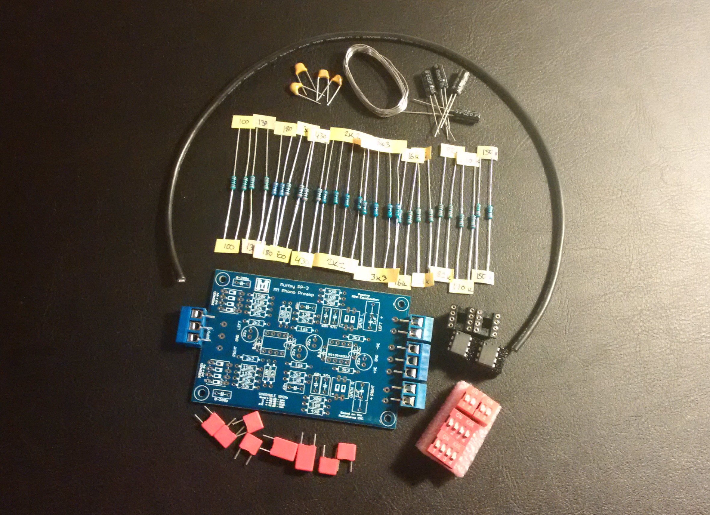
![]()
Going through these steps, you'll be mounting the components above onto the PCB below. You'll also be able to change the circuit to suit your needs, get a few options for powering the phono stage, and finally an example of how to install your project in an enclosure.
Build Instructions Contents
These instructions contains detailed illustrations to guide you through a complete phono stage build. Follow them, and there will be no room for error.
Here are the contents of the guide:
- Steps 3 through 11 show the actual soldering of the board
- Step 12 shows the back panel
- Step 13 shows the audio and power supply wiring
- Step 14 handles the enclosure
- Step 15 describes the different settings on the board
Illustrations Explained
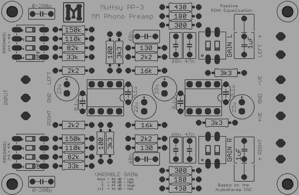
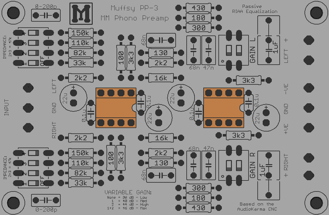
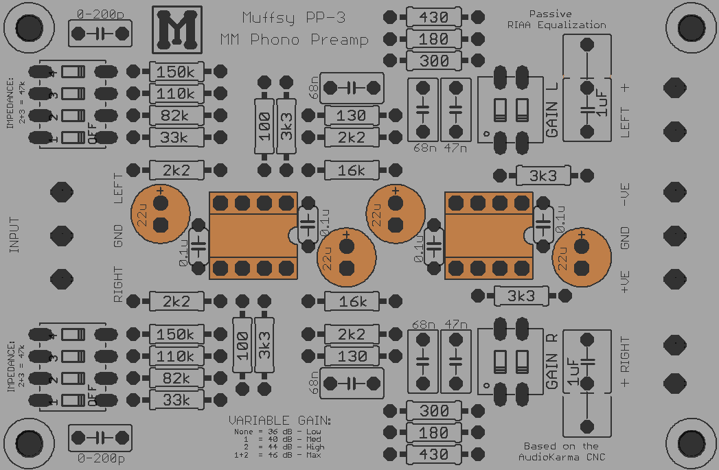
![]()
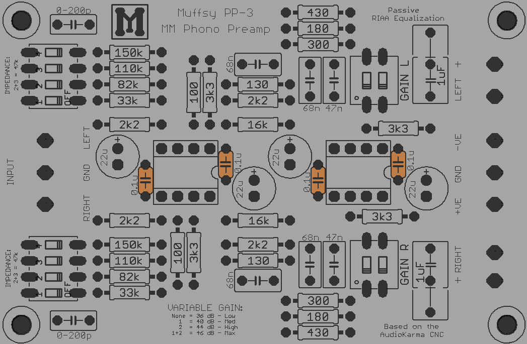
The picture above shows the actual layout of the PCB. It will be used to show which components to solder for each step.
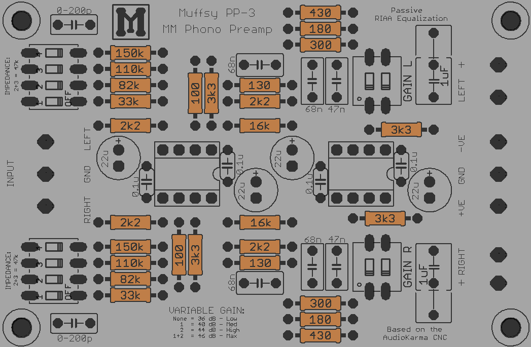
For each step, you'll also get a picture of how the board should look like when the step is completed. This will help you make sure you haven't missed anything. Like this example:
![]()
You can click on all pictures to get high resolution versions.
About the PCB
The high quality printed circuit board has plated-through holes. Do not attempt to drill these holes to make them bigger. Doing so will break the board.
It is safe to drill the four screw holes (one in each corner) to make them larger.
-
3Step 3
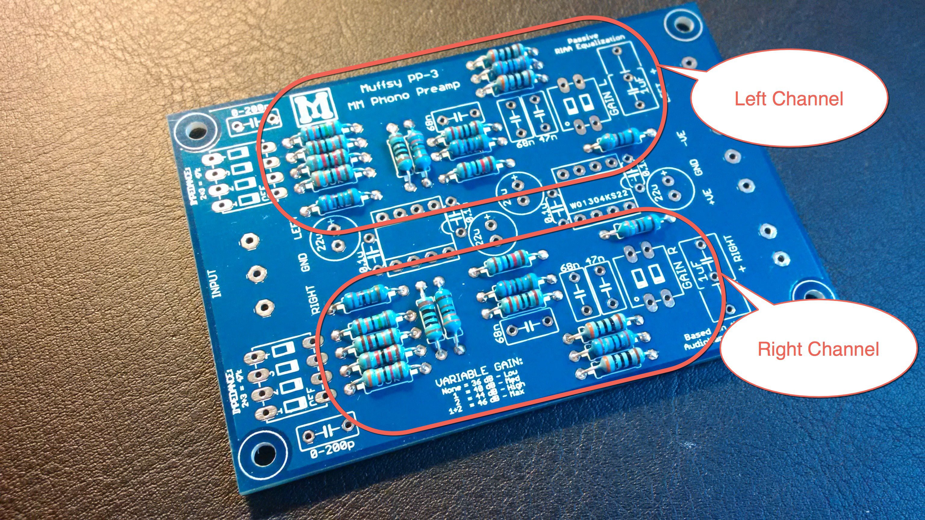
Solder the Resistors
Before you start soldering the resistors, consider if you want to:
- Change the input impedance
- Change the variable gain
- Use other resistors in the audio path
With these decisions made, go ahead and solder all the resistors.
![]()
![]()
Click on the pictures for high resolution versions.
Make sure that the right resistor goes in the right place. Orientation does not matter for the resistors.
-
4Step 4
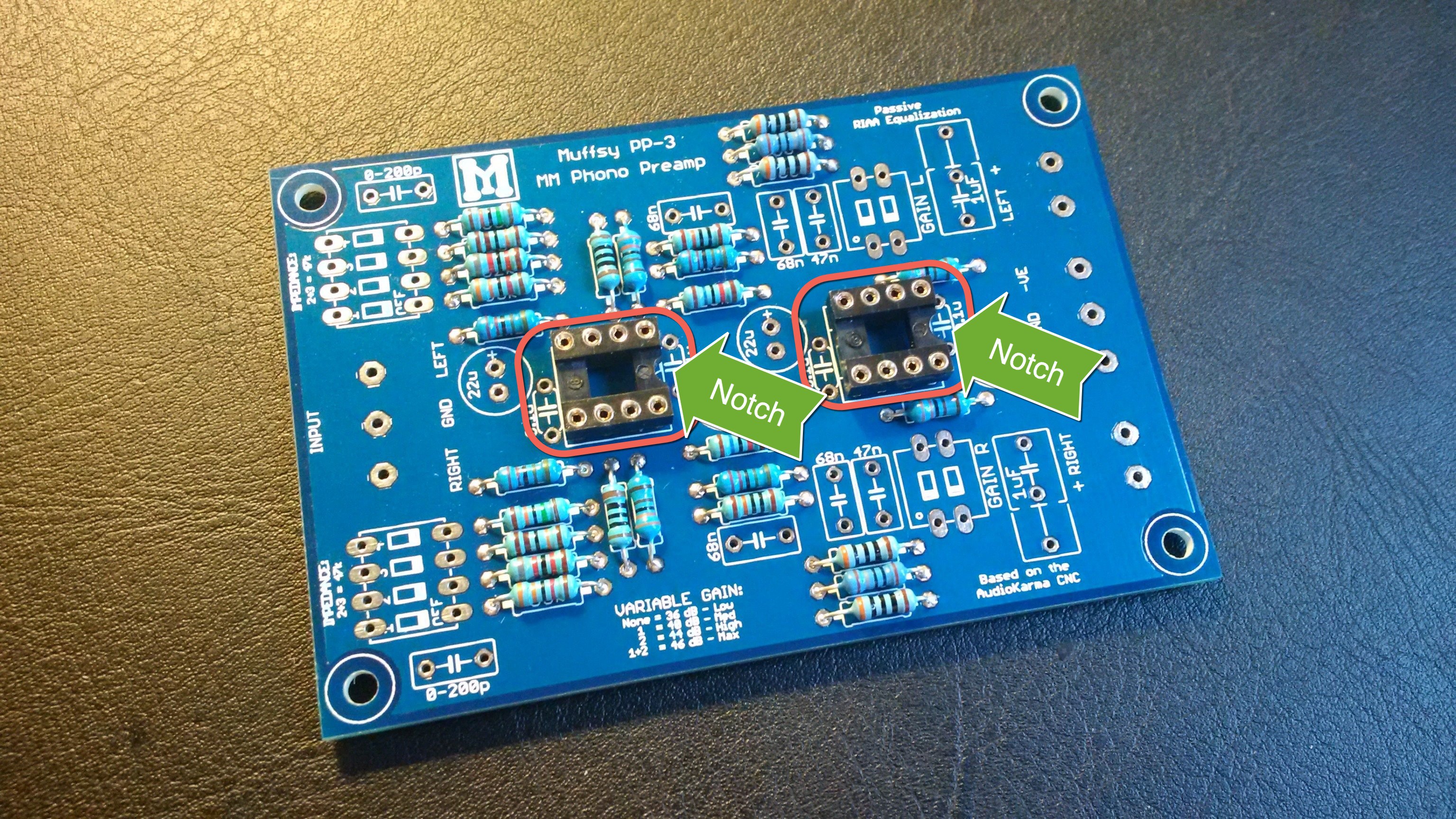
Solder the DIL Sockets
The DIL (dual in-line) sockets are the next components to go on the PCB.
![]()
![]()
Click on the pictures for high resolution versions.
Note that there is a notch in the socket, match this with the notch in the picture on the PCB.
-
5Step 5
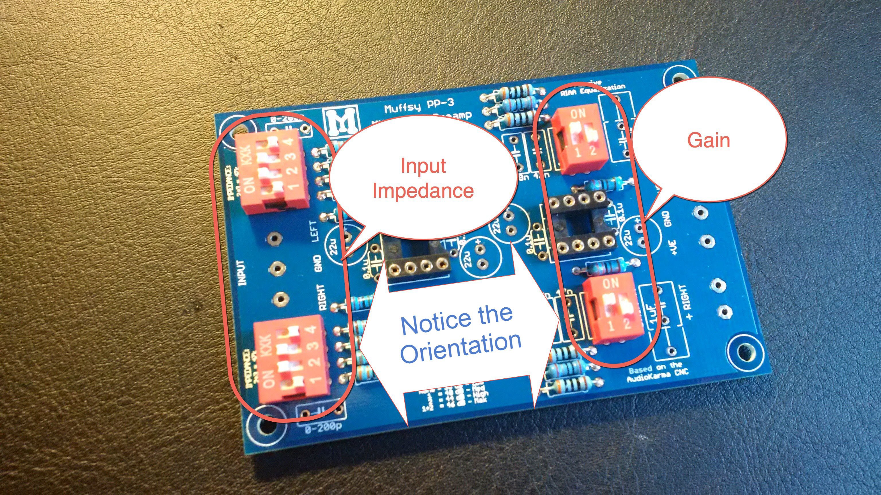
Solder the DIP Switches
The DIP switches go in next. Note the orientation. If you mount the switches the wrong way around, you will have a hard time configuring the right settings for your preamp.
![]()
![]()
Click on the pictures for high resolution versions.
Now is a good time to set the switches 2 and 3 on the input impedance switches to on, and switch 1 on the gain switches to on (as shown in the picture above). This will be your starting configuration. The input impedance is now 47 kohm and the gain will be 40 dB.
-
6Step 6
![]()
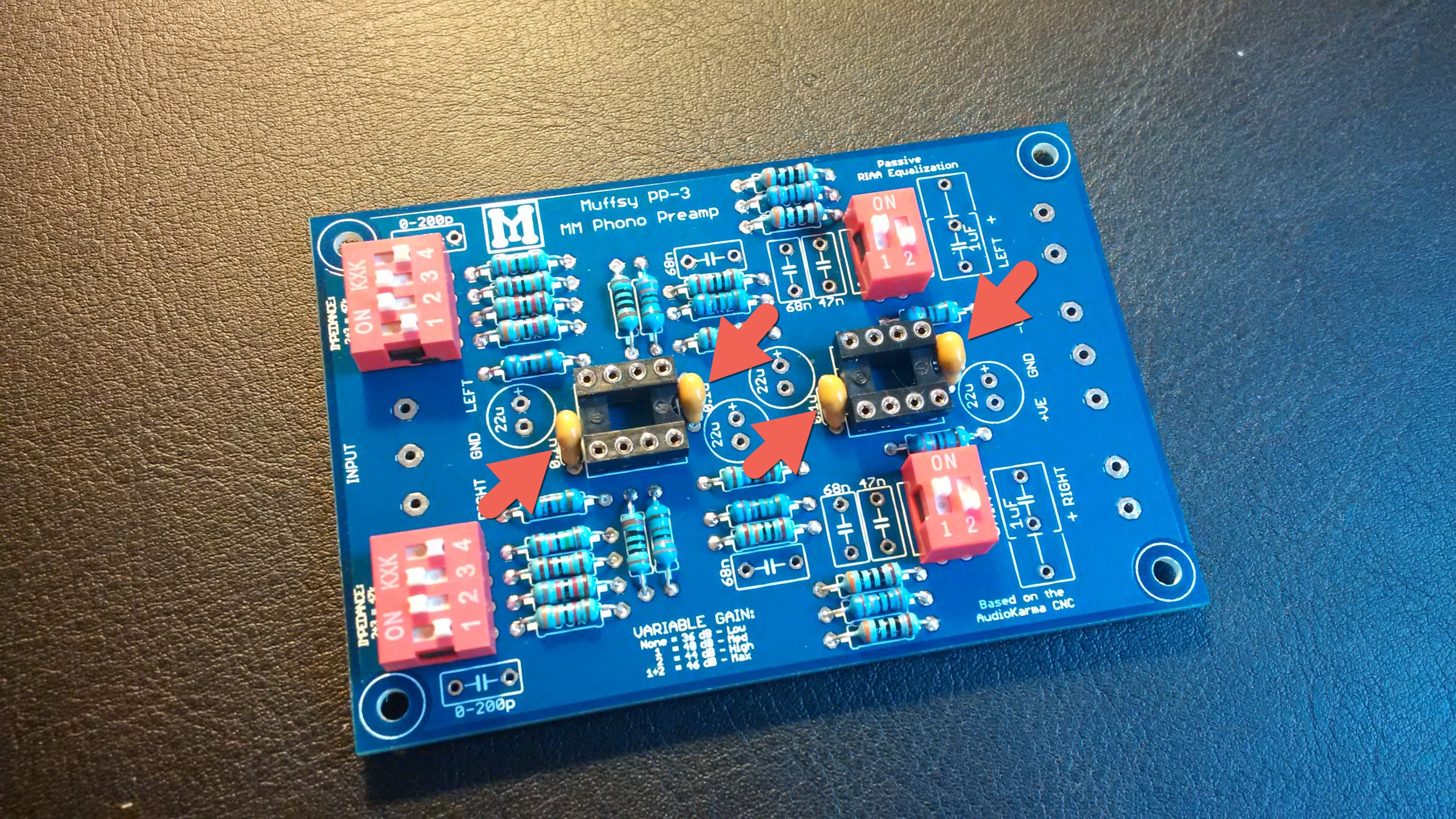
Solder the Ceramic Capacitors
Next, solder the four ceramic bypass capacitors.
![]()
![]()
Click on the pictures for high resolution versions.
Orientation does not matter for these capacitors, i like to have the markings outwards so they can be seen.
-
7Step 7
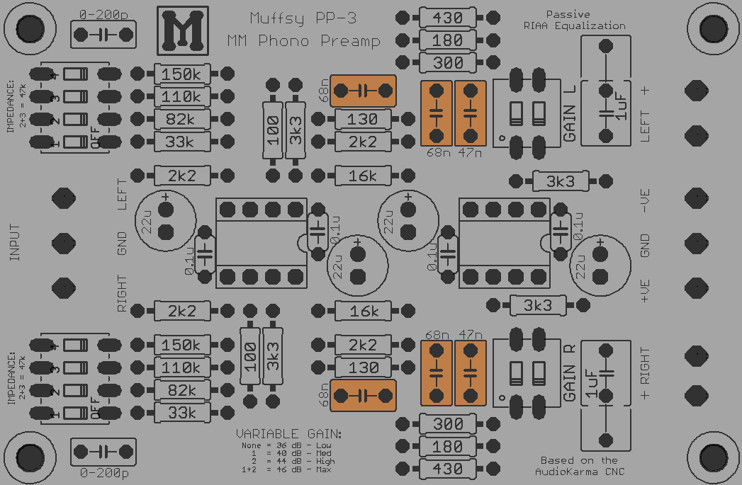
Solder the RIAA Polyester Film Capacitors
These are the polyester film capacitors for the RIAA filter.
![]()
![]()
Click on the pictures for high resolution versions.
Orientation does not matter for these capacitors.
-
8Step 8
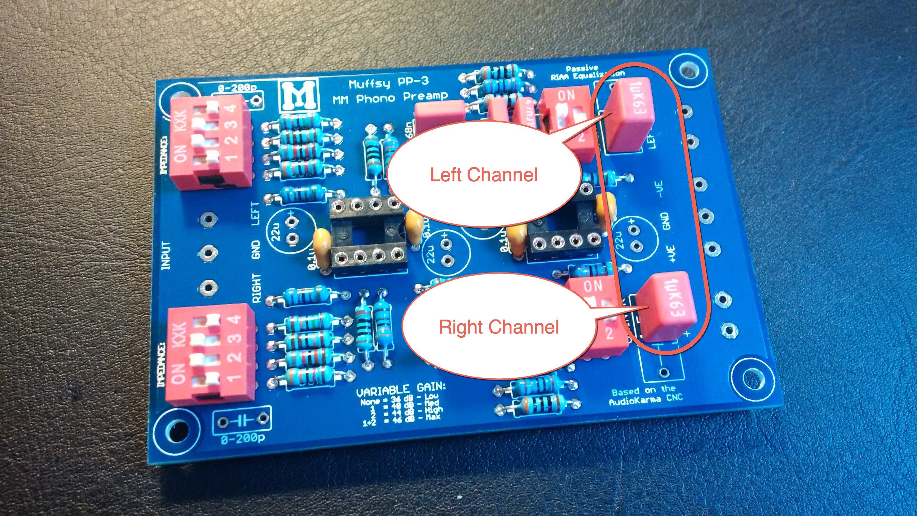
Solder the Output Capacitors
These are also polyester film capacitors, and they are located on the right side of the PCB.
Make sure that they are mounted over the sign that looks like this: -||-. One of the legs must be in the hole towards the center of the board.
![]()
![]()
Click on the pictures for high resolution versions.
Orientation does not matter for these capacitors.
-
9Step 9
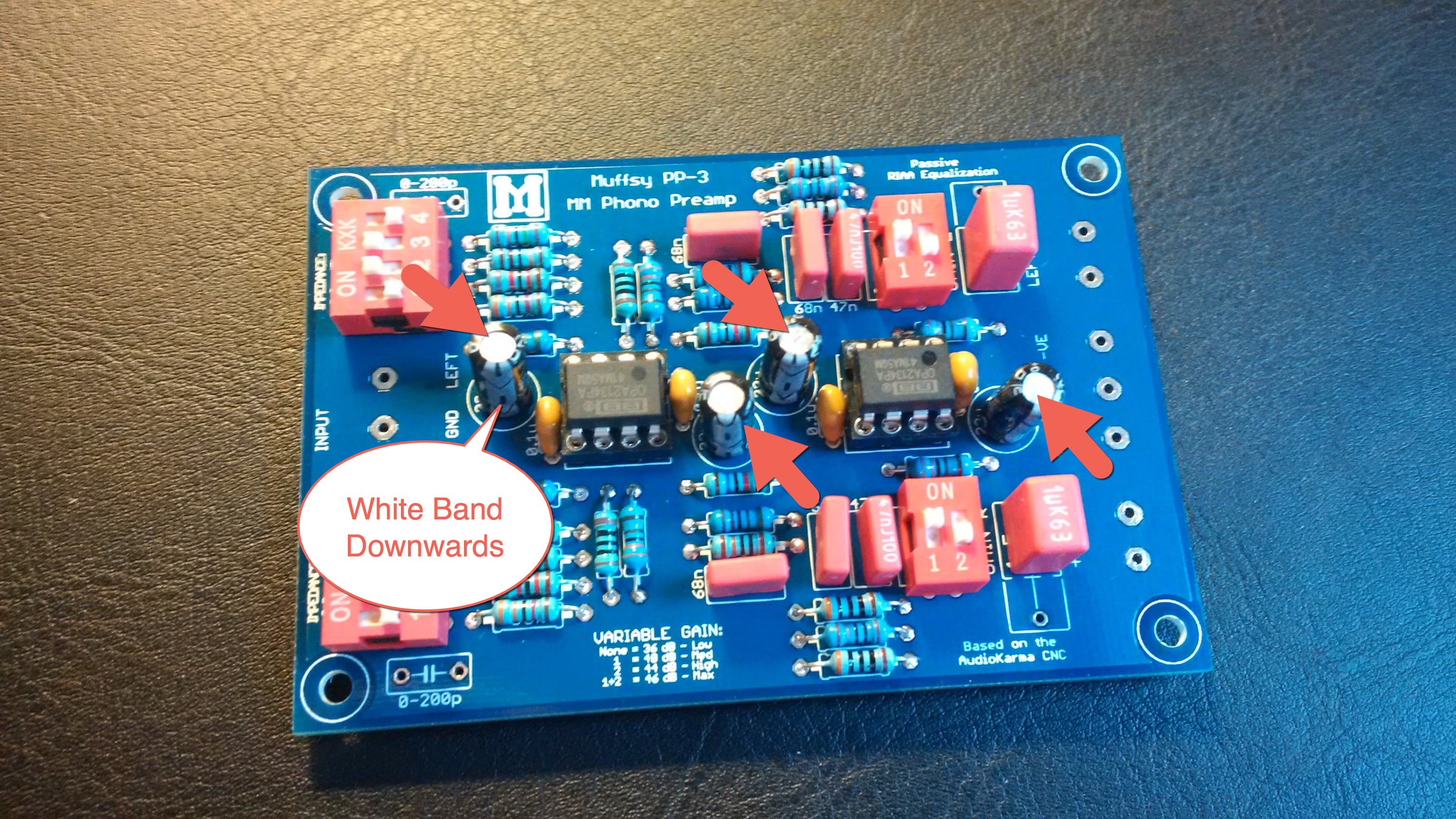
Solder the Electrolytic Capacitors and Mount the Operational Amplifiers
These four capacitors (10 or 22 uF, depending on what you chose when ordering the kit) have to be oriented the right way. The white band shows the negative leg, and points downwards for all four capacitors.
![]()
![]()
Click on the pictures for high resolution versions.
Now is also a good time to mount the operational amplifiers into the DIL sockets. Make sure that the notch or mark on the opamp is oriented the same way as the notch in the socket.
-
10Step 10
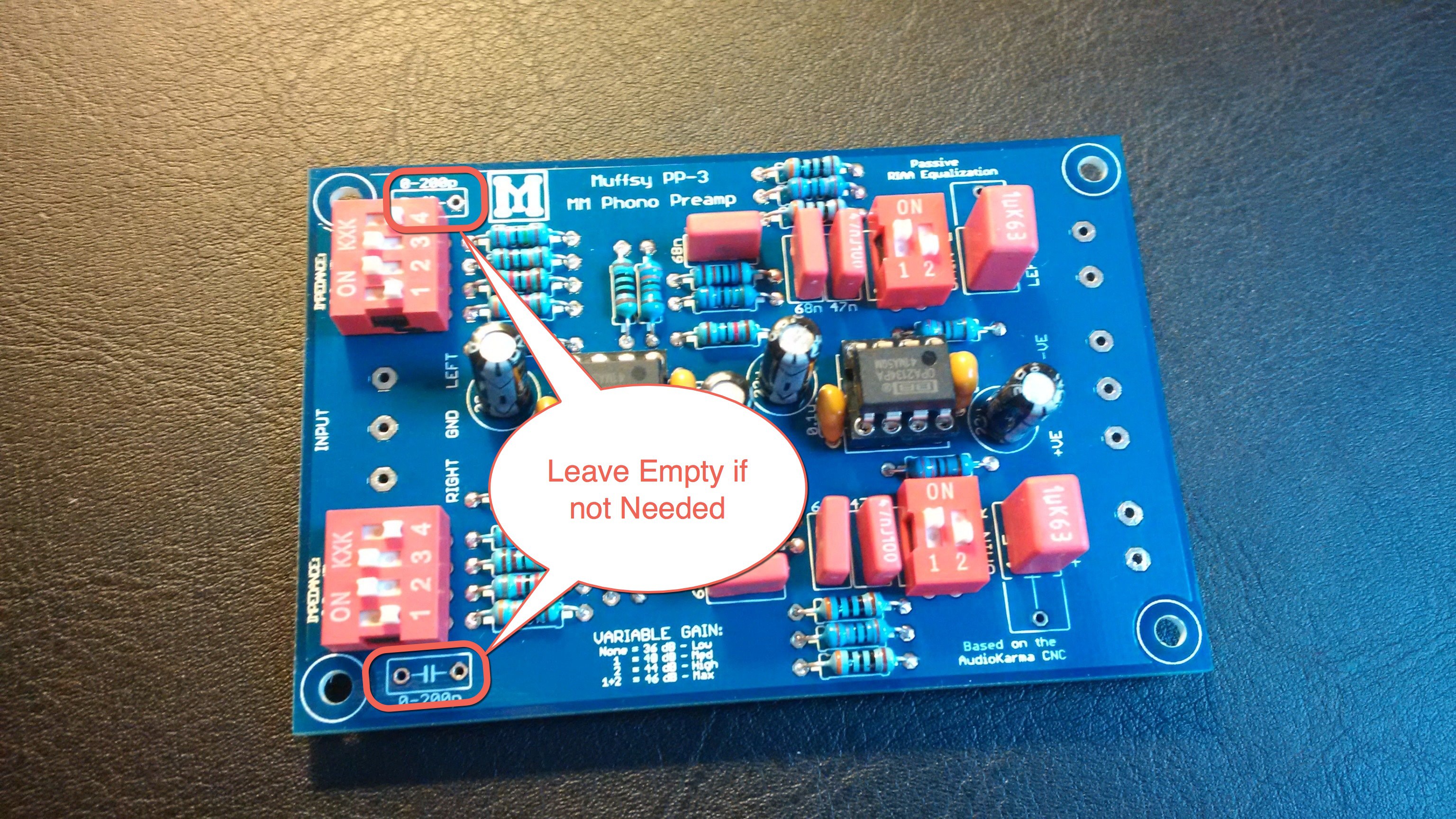
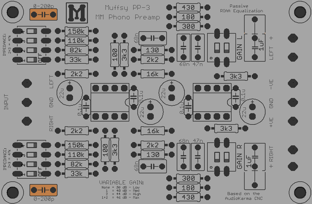
Optional: Solder the Input Capacitors
If you have determined that your phono stage needs additional input capacitance, solder the capacitors in place in the positions shown below:
![]()
![]()
Click on the pictures for a high resolution version.
If you don't need additional input capacitance, which is most likely, leave these positions empty.


Discussions
Become a Hackaday.io Member
Create an account to leave a comment. Already have an account? Log In.