Close
0%
0%

5.5W Diode Laser for CNC

Compact diode laser for CNC, etc.

Similar projects worth following
PROBLEM: No class 4 diode lasers suitable for CNC

About a year ago, I was asked to build a laser that could be mounted to a moving frame for etching and the occasional light cutting operation. One of the requirements was that it had to use one of the new laser diodes that were just coming out at the time.

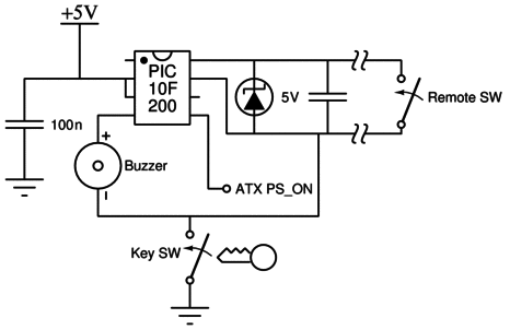
Of course, eye safety is a major concern when dealing with any laser, especially one of this class. It is highly recommended to integrate a safety delay in class 4 lasers. This is where we decided to use a PIC10F200. The turn-on signal and key switch are used as inputs. Outputs are tied to a buzzer and the PS_ON of an ATX power supply. The PIC gives us some additional flexibility over a traditional 555 circuit and does it using less components. It can also be argued that it is more reliable.

Eagle Pair 190 - 540nm laser safety glasses were worn at all times during laser operation. Purchase them from http://survivallaser.com and have enough on hand for everyone who will be viewing the device in operation. Never look directly into the laser beam, even with the safety glasses on. They are for protection against reflections and momentary strikes only and do not protect against direct sustained impingement. DO NOT USE CHEAP EBAY OR AMAZON "SAFETY" GLASSES!!! You only get one set of eyes.

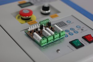
All of the control electronics are integrated into the case of the ATX power supply, leaving only the laser diode itself and cooling fan as external components. I can say now from experience that it is much easier to have all the low voltage electronics in a separate box and go with a 3 piece design.

Diode lasers have much higher divergence and lower output than the CO2 lasers we usually see in cutting machines. To compensate, we must mount the diode very close to the work. Luckily a laser diode is small enough that won't be a problem.

Why not use a CO2 laser then? CO2 lasers have problems of their own. They are bulky, require high voltage and a water cooling loop. Water and electricity are mixing very close together. They are also thin glass and very fragile. Many do not survive a trip through the mail system. Internal misalignment and power fade are also very common. So why are we still using them? It comes down to power density, absorption, and beam quality.

Flexibility of the wiring is also very important. The laser is going to move back and forth many times. Wire breakage could result in replacement of the expensive laser diode. High quality silicone wire is used in the areas where flexing will occur. Flat flex may be even more effective if it can be found with enough traces to carry the >4A of current.

  • 1 × Eagle Pair 190 - 540nm Laser Safety Glasses Protect your vision!
  • 1 × PIC10F200 Microprocessors, Microcontrollers, DSPs / ARM, RISC-Based Microcontrollers
  • 1 × ATX Power Supply At least 4A on the 12V rail
  • 1 × Silicone Wire Different colors, red, black, blue, green, white, etc
  • 1 × Key Switch Switches laser on and off safely

View all 13 components

  • CO2 vs Diode

    The Lightning Stalker08/01/2015 at 18:30 0 comments

    Diode lasers have much higher divergence and lower output than the CO2 lasers we usually see in cutting machines. To compensate, we must mount the diode very close to the work. Luckily a laser diode is small enough that won't be a problem.

    Why not use a CO2 laser then? CO2 lasers have problems of their own. They are bulky, require high voltage and a water cooling loop. Water and electricity are mixing very close together. They are also thin glass and very fragile. Many do not survive a trip through the mail system. Internal misalignment and power fade are also very common. So why are we still using them? It comes down to power density, absorption, and beam quality. CO2 is still the cheapest solution for laser metal cutting.

    But for a hobbyist interested in etching and light cutting of thin materials (not metals unless very thin), diode lasers still have an advantage.

  • PIC10F200 Code

    The Lightning Stalker08/01/2015 at 17:32 0 comments

    ;*******************************************************************************
    ;                                                                              *
    ;    Filename:     Laser_Pantograph.asm                                        *
    ;    Date:         8/5/2014                                                    *
    ;    File Version: 1.0                                                         *
    ;    Author:       The Lightning Stalker                                       *
    ;    Company:      Lightning Industries                                        *
    ;    Description:  Implements countdown timer and remote switch for            *
    ;                    facilitation of compliance with FDA regs.                 *
    ;                                                                              *
    ;*******************************************************************************
    ;                                                                              *
    ;    Revision History:                                                         *
    ;                                                                              *
    ;*******************************************************************************
    
    #define SWITCH      GPIO,GP3        ; Remote switch
    #define COMP        GPIO,GP2        ; Comparator output
    #define PS_ON       shadow,GP0      ; ATX PS_ON
    #define PS_ON_MASK  b'00000001'     ; Bitmask for PS_ON (GP2)
    #define BEEP        shadow,GP1      ; Have a buzzer for some output.
    #define BEEP_MASK   b'00000010'     ; Bitmask to toggle the buzzer
    #define DoIBeep     Beep,0          ; boolean beeping toggle
    
    ;*******************************************************************************
    ; Processor Inclusion
    ;*******************************************************************************
    
    #include "p10f200.inc"
    #include "Debounce.inc"
    
    ; CONFIG
    ; __config 0xFFEB
     __CONFIG _WDTE_OFF & _CP_OFF & _MCLRE_OFF
    
    ;*******************************************************************************
    ; Variable Definitions
    ;*******************************************************************************
    
    GPR_VAR         UDATA
    TimerL          RES 1
    TimerH          RES 1
    TimerE          RES 1
    TimerW          RES 1
    Beep            RES 1
    shadow          RES 1
    
    ;*******************************************************************************
    ; Reset Vector
    ;*******************************************************************************
    
    RES_VECT  CODE    0x0000            ; processor reset vector
        GOTO    START                   ; go to beginning of program
    
    ;*******************************************************************************
    ; MAIN PROGRAM
    ;*******************************************************************************
    
    MAIN_PROG CODE                      ; let linker place main program
    
    START
    
    Reset
        movwf   OSCCAL                  ; load oscillator calibration value
        bcf     OSCCAL,FOSC4            ; disable FOSC/4 output on pin 3
        movlw   b'10011111'             ; put Timer0 in timer mode, set pin 3 as GP2
        option                          ; and enable weak pull-ups
    
    
    Init
        movlw   PS_ON_MASK              ; Clear all output (latch)
        movwf   GPIO                    ; except for GP0, which is inverted PS_ON
        movwf   shadow                  ; and output register shadow
        movlw   0xff                    ; Set GP2 & 3 as input, GP0 & 1 as output
        xorlw   PS_ON_MASK
        xorlw   BEEP_MASK
        tris    GPIO                    ; Load TRIS
    
    ;goto Main ;***************REMOVE*********REMOVE**********REMOVE!!!!!
    ;Sound alarm, light LED, and begin 25 second countdown.
        movlw   BEEP_MASK
        xorlw   PS_ON_MASK              ; remember, PS_ON HAS TO stay high!
        movwf   shadow
        movwf   GPIO
        movlw   .6                      ; Sound alarm for one second
        movwf   TimerE
        movlw   .19
        movwf   TimerH
        movlw   .173
        movwf   TimerL
    Delay1s
        decfsz  TimerL,f
        goto    Delay1s
    
        decfsz  TimerH,f
        goto    Delay1s
    
        decfsz  TimerE,f
        goto    Delay1s
    
        movlw   PS_ON_MASK
        movwf   shadow                  ; Everything off
        movwf   GPIO
    
        movlw   .122                    ; Delay another 24 seconds
        movwf   TimerE
        movlw   .193
        movwf   TimerH
        movlw   .129
        movwf   TimerL
    Delay24s
        decfsz  TimerL,f
        goto    Delay24s
    
        decfsz  TimerH,f
        goto    Delay24s
    
        decfsz  TimerE,f
        goto    Delay24s
    
        goto    $+1
    
    
    Main
    ;Wait for remote signal
        btfsc   SWITCH                  ; someone pressing the switch?
        goto    $ + 5                   ; keep going
        call    SwitchDebounce          ; Debounce it then!
        xorlw   1                       ; Did it
        btfss   STATUS,Z                ; bounce?
        goto    SwitchPressed           ; nope.avi
    
        goto    Main
    
    
    SwitchPressed
        clrf    shadow                  ; Bring laser online
        clrf    GPIO
    
    LaserON
        btfss   SWITCH                  ; Switch still on?
        goto    LaserON                 ; Yes
        movlw   PS_ON_MASK              ; No
        movwf   shadow                  ; Shut the laser off
        movwf   GPIO
        goto    Main
    
    
        END                             ; Directive 'end of program'
    

    Debounce.inc -

    ;******************************************************************************
    ;SwitchDebounce - Waits for switch to release and settle
    ;******************************************************************************
    ; The SWITCH must be a steady high for 10 milliseconds to be considered
    ; released and debounced. The debounce routine sets a 10 mSec timer and looks
    ; for...
    Read more »

  • Controller Schematic

    The Lightning Stalker08/01/2015 at 17:25 0 comments

  • Code, diagrams

    The Lightning Stalker08/01/2015 at 17:21 0 comments

    Posting some code and digigrams

View all 4 project logs

  • 1
    Step 1

    Put everything together

  • 2
    Step 2

    Check for correct polarities, many many times, take frequent breaks

View all instructions

Enjoy this project?

Share

Discussions

George I Fomitchev wrote 06/25/2017 at 20:52 point

  Are you sure? yes | no

RandyKC wrote 06/14/2015 at 12:16 point

Is this schematic for the "Line Drive" you posted about in the Laserforum? I would definitely be interested in seeing how you sourced that much clean current to the laser diode. What is the upper limit for that circuit?

  Are you sure? yes | no

The Lightning Stalker wrote 06/14/2015 at 19:10 point

Line Drive are more advanced and will power up to 15A in the current iteration

  Are you sure? yes | no

RandyKC wrote 06/15/2015 at 01:52 point

I'd be very interested in an earlier version if you'd like to share the schematics. 5A is all I'd be interested in for a diode based design. If I go bigger in the future I'll probably go with a CO2.

  Are you sure? yes | no

RandyKC wrote 06/14/2015 at 05:19 point

Do you have a source for the laser diode?

Is your diode driver LM317 based?

  Are you sure? yes | no

The Lightning Stalker wrote 06/14/2015 at 06:30 point

Source for diodes is DTR,

LM317 will work but are underpowered

  Are you sure? yes | no

Jithin wrote 06/09/2015 at 17:27 point

Conventional laser cutters do not move the laser.  Only the beam. So you won't have to worry about wires with such a design
Mirrors mounted on either axis reflect the beam downwards at the required positions, and usually through a focusing lens.

  Are you sure? yes | no

The Lightning Stalker wrote 08/01/2015 at 17:55 point

Not a problem for a CO2 laser

High divergence and lower output of a diode laser necessitate mounting very close to the work, so we can "squeeze" every last mW

  Are you sure? yes | no

Frank Vigilante wrote 06/09/2015 at 03:54 point

awesome...

  Are you sure? yes | no

Similar Projects

Does this project spark your interest?

Become a member to follow this project and never miss any updates