-
Achievement Unlocked: Beyond Binary
08/24/2015 at 08:35 • 0 commentsNice! I stumbled onto this one by accident. It turns out that the XOR gate is as simple as removing the final pair of comparators from the end of the XNOR I already built. If you think about it, this is *really* obvious. An XNOR is a Negated XOR, so just stop negating it and you have an XOR gate. Here's the schematic.
This is the ternary XOR most strictly adherent to it's binary counterpart according to Kleene logic. It corresponds to the binary connective "Exclusive Disjunction". Due to the expansive possibilities of ternary logic, there are several different truth tables which could have a claim to being the true "Ternary XOR". For example, this gate does not calculate the sum of two trits, while the binary XOR does calculate the sum of two bits. I am arbitrarily selecting this XOR as *the* XOR because Kleene logic says so. It's a straight-up appeal to authority.
And with this gate finished, I have now demonstrated and documented the strictest ternary equivalent of every two-input binary gate possible. From here on out, any two-input gates devised are going to be pushing the boundary of what is even capable of being represented in a binary system. There's still a lot of work to be done (multiplexors, latches, adders, multipliers, etc.) that has already been done with binary circuits, but this project is now at the point where the potential benefits of ternary will actually have a chance to be demonstrated. The point is not to solve every problem of computing by just adapting existing binary circuits to a ternary system. The point is to solve some computing problems in entirely new ways that binary cannot even approximate.
-
More XNOR
08/24/2015 at 05:58 • 0 commentsOops! The XNOR schematic is now updated to make it not fail miserably. Also, I remembered to put the truth table in this time. Here it is.
One thing I forgot to mention about the XNOR gate in a balanced ternary system is that the truth table is also the single-trit multiplication table.
-1 * -1 = 1
0 * 0 = 0
1 * 1 = 1
-1 * 1 = -1
This isn't super-useful since a bunch of XNOR's in a line aren't going to give you a multi-trit multiplier circuit, but it could be useful as a tritwise operator. Assembly programmers and embedded programmers do all sorts of wild sorcery with bitwise operators in binary where they only have between 6 and 15 (depending on the programming language). Just think what people will come up with when they could have *thousands* of tritwise operators available to them...
-
XNOR Gate
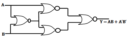
08/23/2015 at 06:18 • 0 commentsI've finished working out the ternary gate most closely analogous to the Binary XNOR gate. In Kleene logic it would be called the Biconditional or the Equivalence connective. I don't have a better name for it, so I'll borrow the boolean term XNOR. This was built using the expedient of copying the boolean method of chaining together four NOR gates like so:
![]()
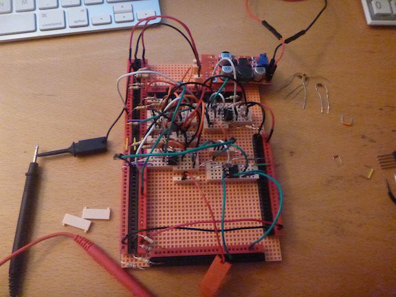
In my ternary system I simply replaced the NOR gates with Antimax gates and it worked nicely. I think I may be able to simplify it a bit, but I'm not sure yet. Here's a picture of the resulting rats nest.
![]()
I tried out the "5E" boards as a replacement for a traditional breadboard. My analysis: They beat the hell out of breadboards in every single way. However, the manufacturing of the power rails is awful. Every insertion is a battle of will. If they just fixed that the 5E board would be totally superior.
In this circuit I changed things up a bit and used LM393's instead of the 319's I've been using thus far. That went pretty well.
And to continue the saga of my diode testing, I attempted this circuit using the small signal silicon diodes. Fail. After replacing a few at random with Schottky diodes it worked. Schottky all the way!
Enough jibber-jabber. Here's the schematic.
-
Last Gates Updated
08/19/2015 at 07:04 • 0 commentsThe Implication, Nonimplication, Converse Implication, and Converse Nonimplication gates are newly tested with the different diodes, found to work nicely, and the schematics have been updated. Here they are.
-
More Updated Schematics
08/17/2015 at 08:20 • 0 commentsI've finished testing the Min, Max, Antimin, and Antimax gates with the Schottky diodes and 470K pull-downs. They work great. I've got two new files up detailing them.
The first is the Min,Max file giving the updated schematic for the Min gate and both the driven and un-driven Max gates. The other is the Antimin,Antimax file giving the Antimin and the driven and un-driven versions of the Antimax gate. They are here and here.
I am now including both types of Max and Antimax gates because the simpler (un-driven) types are more convenient, but the more complex ones need to be defined because if you try to chain a few un-driven gates together I'm sure the voltage drop would corrupt the signal.
I'll be duplicating this process for the 4 remaining gates I've previously worked out (Implication, Converse Implication, Nonimplication, and Converse Nonimplication).
-
Finally Got It
08/15/2015 at 08:37 • 0 commentsI think I'm done screwing around with analog goofiness for a while (hopefully). I've retested all of the monadic gates that require diodes. I've experimented with various resistor values and tried germanium diodes, silicon small signal switching diodes (1N4143's), and Schottky diodes (1N5817's). Using a combination of 2K resistors for the comparator outputs and 470K resistors for the final pull-down after the diode's gives the most desirable voltage outputs across all of the different diode types. The germanium diodes are consistently the best in that they have the lowest voltage drop and give the best 0V value at around 0.030 mV. Next best are the Schottky diodes which have a voltage drop only slightly worse, but which give a 0V value of around 0.080 mV. Finally there are the silicon switching diodes with have a pretty bad voltage drop and give a 0V value of around 0.380 mV. All of them are acceptable and function, but I'm changing all of my schematics to include the 470K pull-down resistor where applicable and making all the diodes Schottky type since they are much cheaper and easier to find than germanium diodes. As an odd note, both the germanium and Schottky diodes work perfectly without the pull-down. I'm including it anyways because it really ought to be there and the circuits fail when using the extremely common switching diodes if the pull-down is not present.
I've updated the monadic gates here, here, and here. The remaining schematics will follow soon and then I can finally get back to working on new gates.
And one other thing. Traditional breadboards are a waste of atoms. I'm going to try these. I don't know if they will be any better, but they can't be any worse.
-
I Hate Breadboards
08/14/2015 at 08:21 • 0 commentsa lot.
-
Back To Basics
08/08/2015 at 08:05 • 0 commentsWell I *still* haven't built an XOR or XNOR gate, but I did learn a few important things which will result in yet another revision to many of my existing gate schematics in the very near future.
When I started this project I just used a bunch of diodes I had lying around from an old radio project. They are old-school germanium diodes rather than the ubiquitous silicon diodes in use nowadays. I built all of my circuits with them and all was well until I ran out. When i tried to use silicon diodes, I kept on getting wild oscillations all over the place. Eventually a helpful stackexchange answer set me straight. I needed to provide a pull-down resistor just after the diodes on any gate using them. This makes sense, but I'm still confused as to why the germanium diodes worked without the pull-down. Also, after much testing, I found the surprisingly large value of 470K ohms to work the best with both the germanium and the silicon diodes.
I also did more thorough tests of the LM393 and TLC3704 comparators to determine their usefulness as space-saving measures as I start to get into more complex circuits. Both are more limited than the LM319 as to which gates they can be used to produce, but they are both smaller packages so if I happen to need a few gates out of the list one or the other can make, I might do so rather than stick another 319 on the board.
-
Updated Two-Input Gates
07/30/2015 at 07:33 • 0 commentsThe new simpler Min, Max, Antimin, Antimax, Implication, Nonimplication, Converse Implication, and Converse Nonimplication gates have been updated and tested following my face-palm moment. The schematics are here and here.
Next up, the ternary equivalents of XOR (Exclusive Disjunction) and XNOR (Biconditional). I think I've got them figured out.
-
On Naming Two-Input Ternary Gates
07/29/2015 at 06:27 • 0 commentsI've been thinking about how to give each of the 19,683 two-input gates their own names that won't be ridiculously long, but which will uniquely identify each one. I couldn't find anyone having proposed a solution, but came up with a pretty good one. Take the truth table for the Implication gate.
- 0 + B B B - A + + + 0 A 0 0 + + A - 0 + There are three rows of three values. I simply take each row, and find the monadic gate associated with that pattern of values. In this example the first row is +++, which corresponds to a monadic Z gate, the second is 00+, an R gate, and the final row is -0+, a P gate. So this gate would be designated a ZRP gate. This solves the problem of the many thousands of gates that will never have a name but might pop up from time to time in some design or another. I'm sure the gates found to be useful will eventually develop colloquial names, but for all the others this should suffice.
Tern - Ternary Logic Circuits
A series of ternary logic gates and higher level components implemented in the real world.