Close
0%
0%

Project 'Landlord'

Open source firmware for Worx Landroid robotic mower.

Similar projects worth following
Reverse engineering and develop a new and open source firmware for the Worx Landroid robotic mower family. Add new features. Smarter algoritm. Add GPS for smarter navigation.

DB275 models uses a NXP LPC1768 arm Cortex-m3.
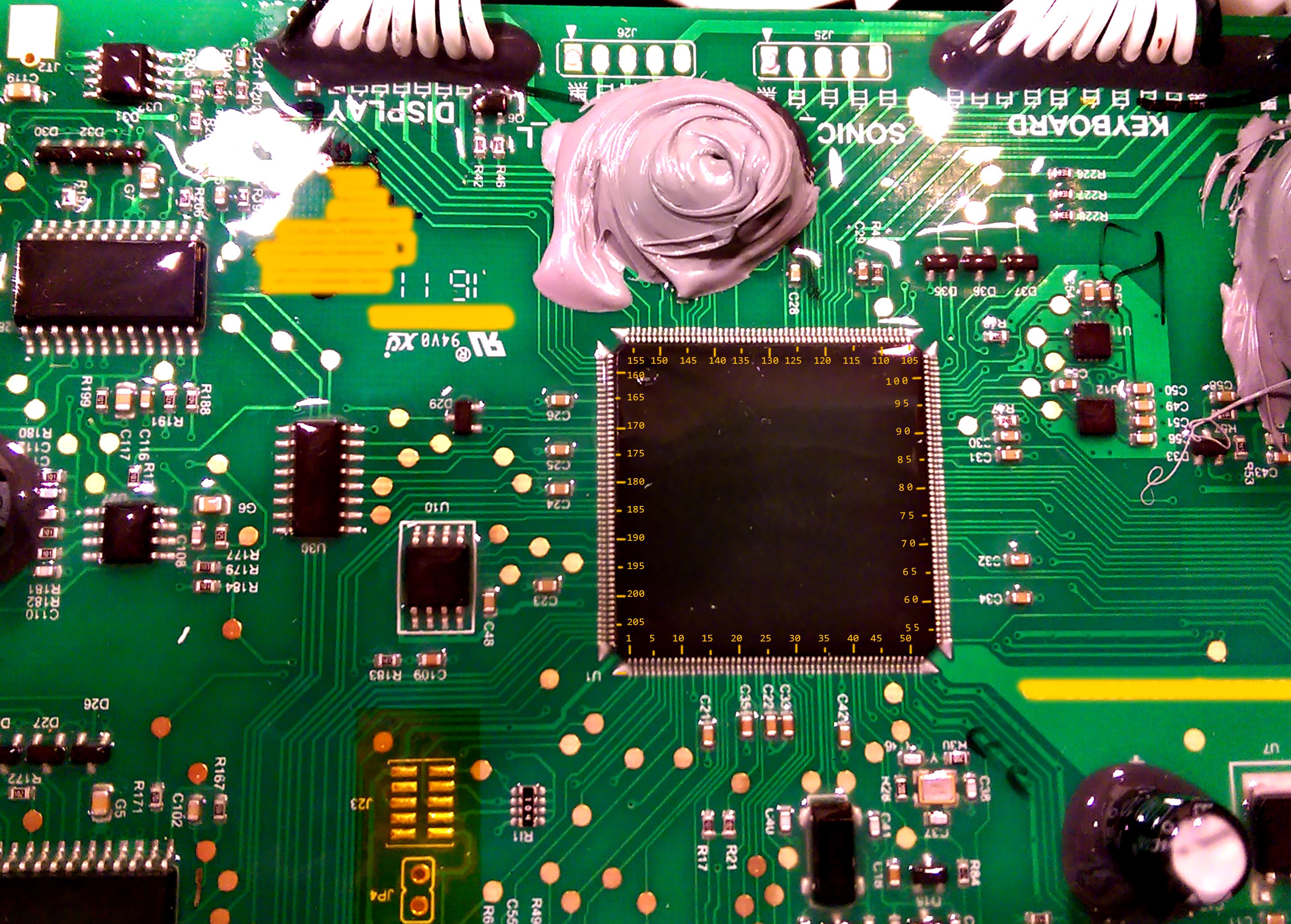
DB504 models are very similar to DB275 but uses a NXP LPC1788 arm cortex-m3.
DB297 models - please share images!


IC's on DB275-10:


IC's on DB504-03:

The onboard bootloader checks USB after memory stick after firmware file and flashes the its contents.
Custom firmware does not overwrite the bootloader, so it is possible to revert to original firmware.
DB275 firmware start at 0x9000
DB504 firmware start at 0x10000


Source code: https://github.com/Damme/LandLord

To setup build enviroment follow How to install the ARM toolchain
Also possible to use KEIL-MDK.


Please feel free to donate money.
I currently own thrr landdroid's. Two 791e 2015, 794e 2014 - with DB275 motherboard and one wg791e.1 (2016) with DB504.

Bitcoin: 3FnkdzXjkyeHK5o5H3wzM9jDzw52Q3GEog

  • 1 × Brave owner In case the mower starts chasing your pets and begins to burn under your car!
  • 1 × Worx Landroid https://www.worxlandroid.com/
  • 1 × USB stick generic for flashing firmware - FAT32 formatted

  • Working on integratin OpenMower project

    Daniel Wiegert05/15/2022 at 07:55 0 comments

    Hello all, I am getting quite a few PMs about this project.

    I recently started programming again with the goal of making the firmware able to talk to OpenMower. https://github.com/ClemensElflein/OpenMower

    The code on my GitHub is NOT READY YET. At the moment lpc1788 version of the code compiles but not the lpc1768. I am prioritizing LPC1788 at the moment but then that is somewhat ready for use I will start looking at the lpc1768 code again.

    Pinout diagram can be found at https://github.com/Damme/LandLord

    edit; spelling

  • Not the update you all wanted I guess..

    Daniel Wiegert09/28/2021 at 10:51 0 comments

    Hello all!

    First of all, Sorry for not answering you guys at all more or less. Also, I just noticed the link is bad to the io diagram so here is the link again:
    https://drive.google.com/file/d/0B98aBL1DeE4uc3hLQUhHa1FXUGs/view?usp=sharing&resourcekey=0-qmhrLCdqSrvEi-HP7xEJgg

    And the progress? Well there is none. I didn't have energy or time to continue at the time and I also hoped that competition in the market would make the machines better. Not WORSE what I can see they went. So in my eyes the competition only made companies want more profit from existing customers... Sadly.. 
    I also made some progress with DB504 model. I made both 504 & 275 able to move around, start stop mower, start stop charging etc. but this is where I stopped.


    There are techniques to have GPS based navigation down to a few cm position (With RTK gps base station etc)
    I am pretty sure it would be possible to program a simple map only with compass and length meter too, it wouldn't be precise at all but I'm sure basic navigation with this technique would be possible, especially with the modern mcu:s that has a lot of compute power.

    So where am I with this project today?
    I am still interested in developing a new firmware. Especially since no progress have been made at all what I can see in the market..

    Worx still seems pretty cheap and rather easy enough. I don't have any motherboards from the later year models at all. Hopefully they haven't changed much at all but I have no idea.
    So if anyone out there would like to dokument, take hi res photos (Without a potato camera please!) I might be able to cross reference the different models. If I would continue this it would not be very smart to use a soon 8 year old robot for this. but if the motherboards are close enough the code could be somewhat universal.


    Hopefully some of you that are truly interested in this project developing a new firmware are getting this message and maybe we can figure something out together.

    //Daniel

  • Battery

    Daniel Wiegert07/21/2016 at 20:50 3 comments

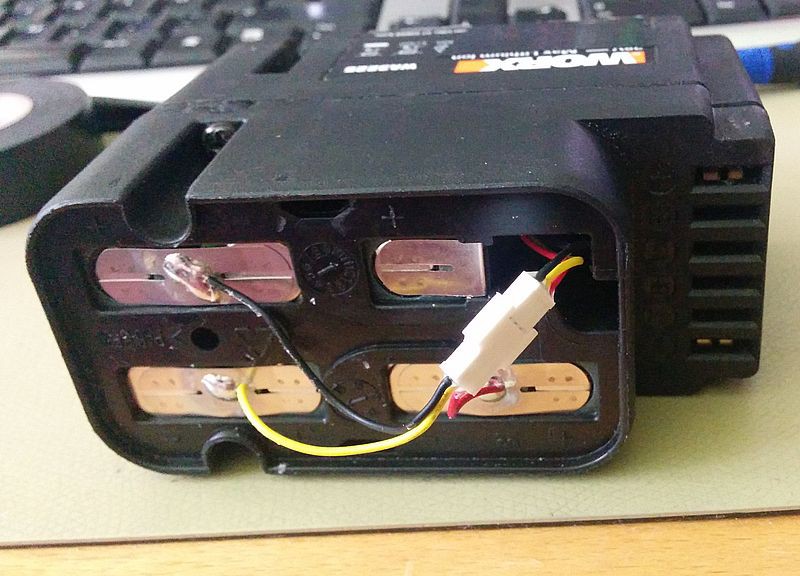
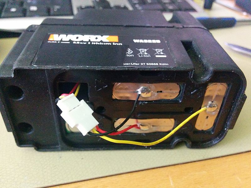
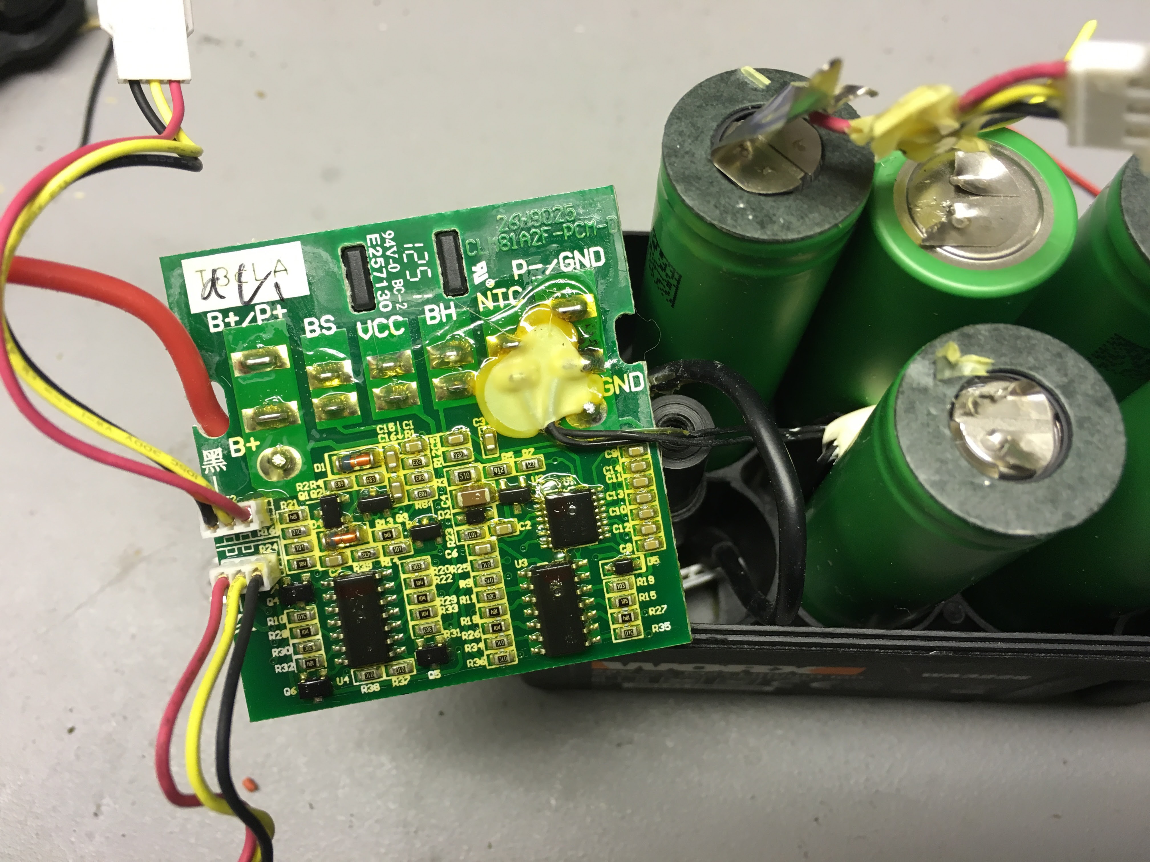
    There have been some discussion over batteries and charging down in the comments. I'll publish images of inside of battery.

    The tabs are solders After case is screwed together. So to split it you need to cut the connecting tabs on one side...

    Cells are Sony 18650 1900mAh. Thanks to Jan B!

  • Unpacker for firmware .pck

    Daniel Wiegert07/19/2016 at 19:09 6 comments

    Warning etc etc, use with caution... Might contain bugs :)

    #!/usr/bin/python3.5
    import sys
    if len(sys.argv) <2:
      print( "usage:" )
      print("  " + sys.argv[0] + " [.PCK file]", "[Folder-prefix]" )
      print( "  " )
      exit()
    import os
    from binascii import crc32
    from struct import unpack
    #get unpack file
    src_file_path = sys.argv[1]
    #read file length
    src_file_size = os.path.getsize(src_file_path)
    #read file
    b = bytearray(open(src_file_path, 'rb').read())
    # crude bytearray to String converter
    def toStr(b):
      return "".join(["%c"%i for i in b]).strip("\x00")
    # convert 4 bytes to int
    def word2int(w):
      return unpack("<I", w)[0]
    # crude filetable parser
    def getHeader(b, datastart):
      beginstart=b.find(63) #"?"
      filename = toStr(b[0:beginstart]).replace("\\","/")
      beginstart+=1
      beginlength=b.find(63,beginstart) #"?"
      start = int(b[beginstart:beginlength],16) + datastart + 4
      beginlength+=1
      length = int(b[beginlength:beginlength+10],16)
      return {
        "filename": filename,
        "start" : start,
        "length" : length,
        }
    #crude way to create nonexisting directories
    def checkCreateDir(filename):
      if not os.path.exists(os.path.dirname(filename)):
        try:
            os.makedirs(os.path.dirname(filename))
        except OSError as exc: # Guard against race condition
            if exc.errno != errno.EEXIST:
                raise
    def save(filename, data):
      checkCreateDir(prefix + "/" + filename) #create missing directories
      print ("writing %s\t (%d bytes)"%(filename,len(data)))
      open(prefix + "/" + filename, 'wb').write(data)
    ## Start decoding
    print("Unknown byte 0:\t"+ str(b[0]))
    print("Unknown byte 1:\t"+ str(b[1]))
    print("Unknown byte 2:\t"+ str(b[2]))
    print("Unknown byte 3:\t"+ str(b[3]))
    prefix = sys.argv[2] if len(sys.argv)>=3 else "."
    headerstart_token = bytearray((int(62), int(0x0d), int(0x0a)))
    headerstart = b.find(headerstart_token,0)+3
    pos=headerstart
    datastart_token = bytearray((int(0x0d), int(0x0a), int(0x0d), int(0x0a)))
    datastart = b.find(datastart_token,0)
    print("header end: \t"+ str(datastart))
    nHeaders = b.count(int(13),4,datastart)
    print("# files \t: "+str(nHeaders))
    # crude way to parse the directory table
    files = []
    print ("found %i files\n"%nHeaders)
    token = bytearray((int(0x0d), int(0x0a)))
    for i in range(nHeaders):
      pos2=b.find(token,pos)
      h = getHeader(b[pos:pos2], datastart)
      files.append(h)
      print(h)
      pos = int(pos2)+2
    for h in files:
      bFile = b[h["start"]:h["start"]+h["length"]]
    #write stripped file
      save(h["filename"],bFile)
    print("Done!")
    

  • Help identifying component (solved)

    Daniel Wiegert07/06/2016 at 08:24 4 comments

    The right one, its a ST L3GD20H, Thanks Ajlitt!


    Left is MMA8452Q, 3-axis, 12-bit/8-bit digital accelerometerhttp://www.nxp.com/files/sensors/doc/data_sheet/MMA8452Q.pdf

  • Pinout DB504

    Daniel Wiegert06/27/2016 at 19:57 3 comments

  • Different motherboards.

    Daniel Wiegert06/20/2016 at 21:16 2 comments

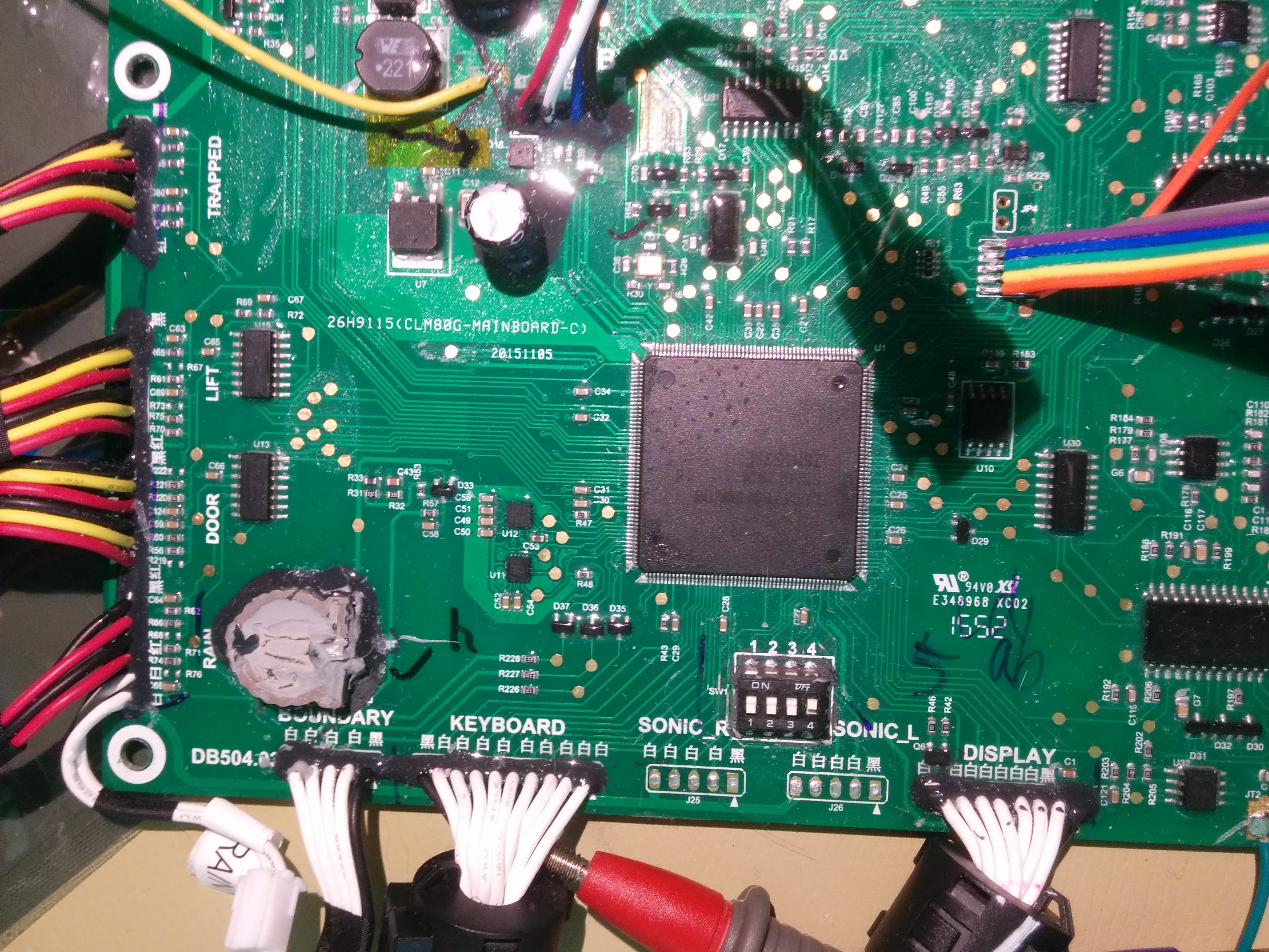
    I've been working on mapping 2016 year model of worx, they use DB504 motherboard. Usually .pck-firmware, its a container and the start is plain-text. It's possible to do a splitter for that but I use dd to copy out the firmware.

    DB504 probably use LPC1788. I've been looking on some io's on a picture I've recieved and it seams to be correct. (not possible to read chip text without removing the conformal coating)

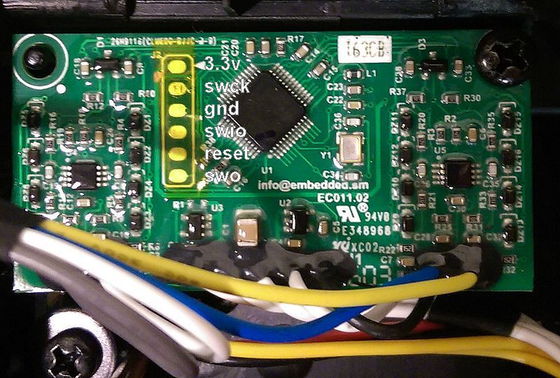
    My guess so far is U10 = spi flash. U11 + U12 compass / accelerometer / gyroscope. Yellow tape protects JTAG from the coating

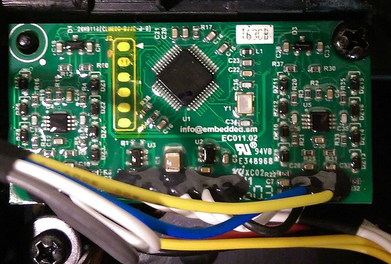
    Display and Keyboard are the same as previous models. Wire sensor uses a daughter board:

    Should we assume they still uses LPC and that this might be an LPC11U6x?

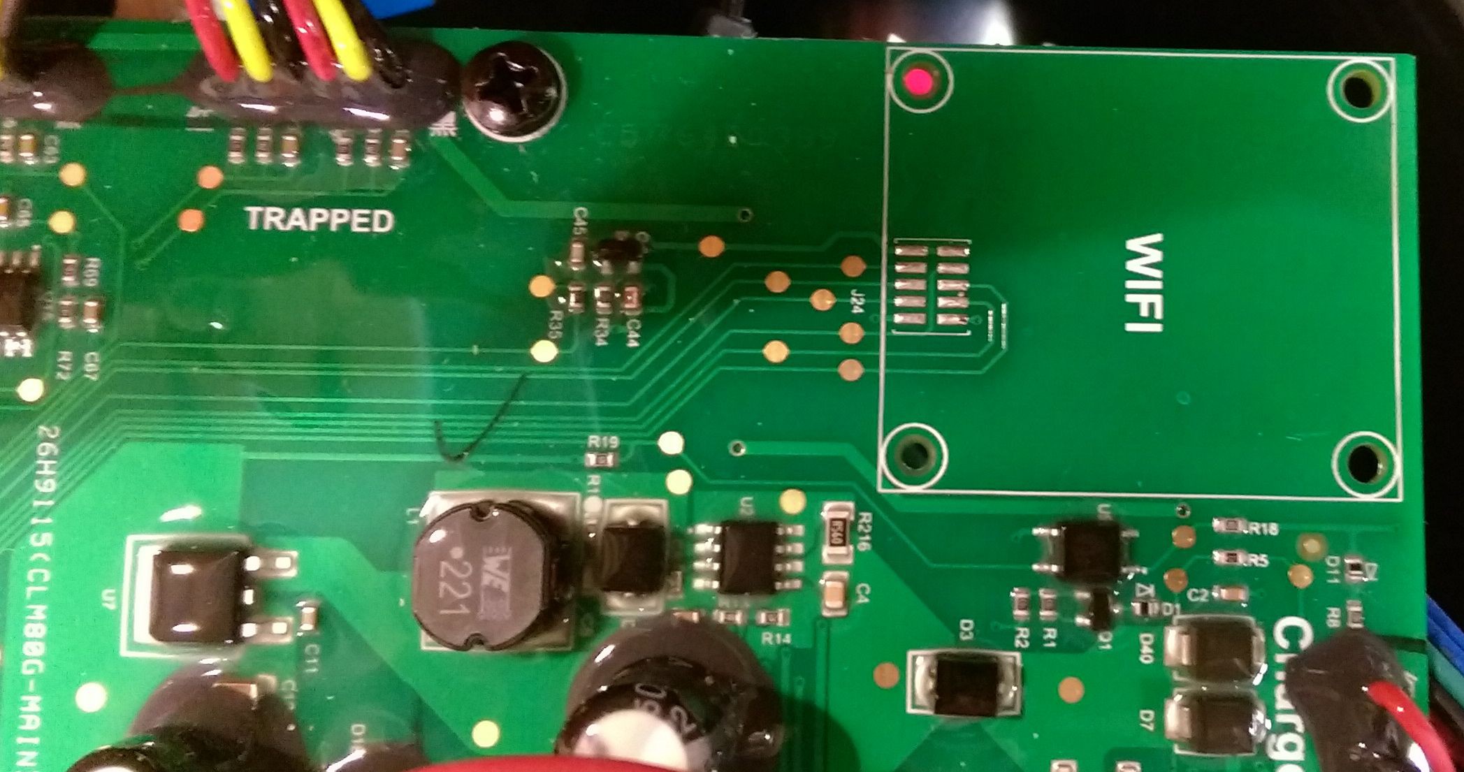
    Wifi module are supplied from http://www.redpinesignals.com/, uses SPI (SSP0) communication. easy to mod! :)

    ( https://www.ghielectronics.com/catalog/product/282 looks like a suspect...)

    So far I've been developing and reversing DB275 (2015 WG790/791/794) It seams all 2016 has DB504.
    WG796e (2015) uses DB297 which I haven't seen yet. So if any one wants to send in pictures of that motherboard it would be very appreciated!

    I don't know much about earlier versions.

    //Daniel

    edit:

  • Some / Slow progress

    Daniel Wiegert06/07/2016 at 09:05 2 comments

    I had a small break, I let the mowers do their job outside! :)

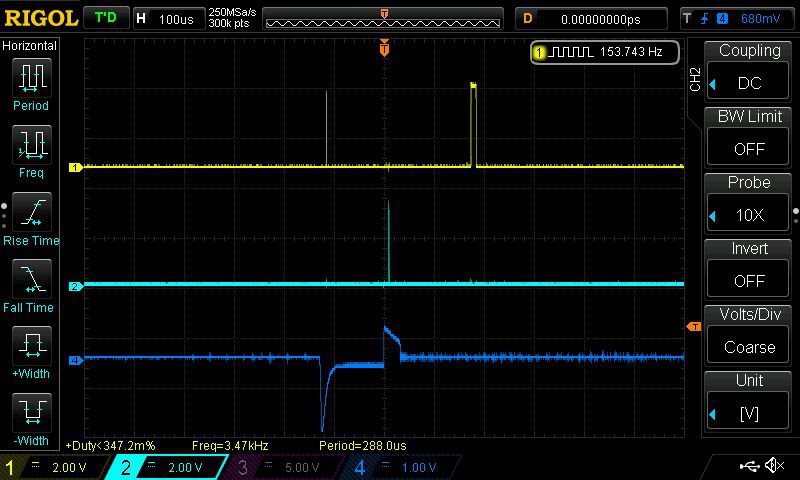
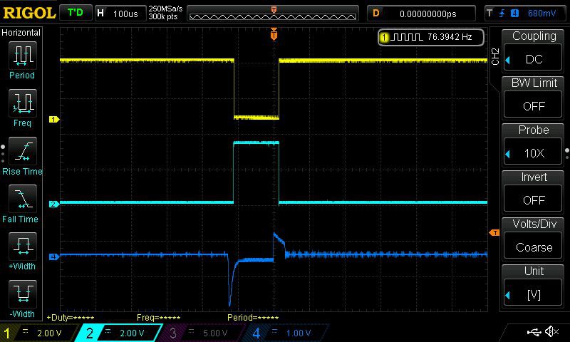
    I've figured out the boundary wire and how it works. I finally got the idea to use the USB d+ and d- (p0.29 + p0.30) and output of p0.7 - p0.10 and measure with oscilloscope.. :) (4 wire inputs -> raising and falling each on pos / neg)

    The blue is probe directly on the boundary wire.

    So if negative measurement is before or after the positive, then you know if you are inside or outside wire.

    p0.21 select amplification or something, you can detect if you are within 1 meter of the wire or not.

    p0.22 probably selects between left and right sensor.

    And if you are close to the sensors you get some weird artifacts in the measurement, longer pulse, and even more than one pulse. It seams this is following a pattern and it might be possible to user and detect the distance to the wire at 0cm, 10cm, 20cm and 100cm.

    And the last one, wire right on top of the sensor.

  • Original firmware?

    Daniel Wiegert05/06/2016 at 12:32 4 comments

    I could use some owners help. I would like to have your firmware-files!
    I need to see how big of a difference it is between models.

    Please contact me!

    Thanks all!

  • Pinout!

    Daniel Wiegert05/03/2016 at 08:14 0 comments

    95% of the pin-out is finished. There are some questions still to be answered. Also the models with WIFI, How do they look inside? I would love to see some pictures of the main board in that one!

    One guess would be that the un-populated IC nead RTC battery is a SPI flash but not confirmed.

    Next important step would be to understand the how the wire sensor works.

    P0.0  GPIO Output, Motor Left, Select Forward/Reverse
    P0.1  GPIO Input, Dip switch 3
    P0.2  ADC6, Motor Right, Current ?? -> Need more investigation
    P0.3  ADC7, Motor Left, Current ?? -> Need more investigation
    P0.4 + P0.5 GPIO Output, Selector ADC4 input -> accelerometer LIS352AR pin S0, S1.
      0    0 - ADC4 = X
      0    1 - ADC4 = Y
      1    0 - ADC4 = Z
      1    1 - ADC4 = aux (temp batt)
    P0.6  GPIO Output, Speaker High volume
    P0.7  GPIO Input, ExtInt3 Raising edge - Wire sensor -> Need more investigation
    P0.8  GPIO Input, ExtInt3 Falling edge - Wire sensor -> Need more investigation
    P0.9  GPIO Input, ExtInt3 Raising edge - Wire sensor -> Need more investigation
    P0.10 GPIO Input, ExtInt3 Falling edge - Wire sensor -> Need more investigation
    P0.11 GPIO Output, Enable Charging (in charger, after P1.23 is set to 1)
    P0.15 SPI SCLK, LCD
    P0.16 SPI CSB, LCD
    P0.17 SPI MISO, LCD <- Unused? NC?
    P0.18 SPI SDA, LCD
    P0.19 SPI RSTB, LCD
    P0.20 SPI A0, LCD
    P0.21 GPIO OUTPUT, Selector Guide Wire sensor, Range / Amplification
    P0.22 GPIO OUTPUT, Selector Guide Wire sensor, Unknown function -> Need more investigation
    P0.23 ADC0, Charge current? (Or Charge voltage, Only >0 then charging) 
    P0.24 ADC1, Voltage Battery
    P0.25 ADC2, Accelerometer, Sideways (X/Y)
    P0.26 ADC3, Accelerometer, Forward (X/Y)
    P0.27 GPIO Input, Motor Rotor, Rotation tick? -> Need more investigation
    P0.28 GPIO Input, Charger state? Battery full? -> Need more investigation
    P0.29 USB D+, Maybe used for softUART for GPS / External mcu communication
    P0.30 USB D-, Maybe used for softUART for GPS / External mcu communication
    
    P1.0  GPIO Input/Output, Keypad matrix Row1
    P1.1  GPIO Input/Output, Keypad matrix Row2
    P1.4  GPIO Input/Output, Keypad matrix Row3
    P1.8  GPIO Input/Output, Keypad matrix Row4
    P1.9  GPIO Input/Output, Keypad matrix Col1
    P1.10 GPIO Input/Output, Keypad matrix Col2
    P1.14 GPIO Input/Output, Keypad matrix Col3
    P1.15 GPIO Input/Output, Keypad matrix Col4
    P1.16 GPIO Input, Hall Sensor, Lifted
    P1.17 GPIO Input, STOP Button
    P1.18 Unknown, NC?
    P1.19 Unknown, NC?
    P1.20 GPIO Output, LCD Backlight ON, PWM1.2 can be used here if motors are inactive. (Pulsing screen then charging)
    P1.21 GPIO Input, High then connected to charger and charger is RED
    P1.22 Unknown, NC? USB Power on??
    P1.23 GPIO Output, Initiate Charger, Keeps charger in RED mode. if low charger shows green light.
    P1.24 GPIO Output, Speaker Low volume
    P1.25 GPIO Output, Keep high for PCB Power on.
    P1.26 Unknown, NC? Sensor?
    P1.27 Unknown, NC? Sensor?
    P1.28 GPIO Input, Power key, Normal HIGH
    P1.29 GPIO Input, Sensor, Rain
    P1.30 ADC4, Output from LIS352AR, Selected by P0.4 + P0.5
    P1.31 ADC5, Motor Rotor, Current ?? -> Need more investigation
    
    P2.0  PWM1.1, Motor Right speed
    P2.1  PWM1.2, Motor Left speed
    P2.2  PWM1.3, Motor Rotor speed
    P2.3  GPIO Input, Dip switch 2
    P2.4  GPIO Output, Motor Right, Enable/Start | Disable
    P2.5  GPIO Output, Motor Right, Brake ON/OFF
    P2.6  GPIO Output, Motor Right, Select Forward/Reverse
    P2.7  GPIO Input, Dip switch 3
    P2.8  GPIO Output, Motor Left, Brake ON/OFF
    P2.9  GPIO Output, Motor Left, Enable/Start | Disable
    P2.10 GPIO Input, EInt0??, Sens Motor? Error?  -> Need more investigation
    P2.11 GPIO Input, EInt1 Edge, Motor Right Rotation tick
    P2.12 GPIO Input, EInt2 Edge, Motor Left Rotation tick
    P2.13 GPIO Output, Motor Rotor, Enable/Start | Disable
    
    P3.25 GPIO Output, Motor Rotor, Brake ON/OFF
    P3.26 GPIO Output, Motor Rotor, Select Forward/Reverse
    
    P4.28 GPIO Input, Hall Sensor, Cover
    P4.29 GPIO Input, Hall Sensor, Front

View all 21 project logs

Enjoy this project?

Share

Discussions

tgrauss+ wrote 05/19/2019 at 10:45 point

Hi,

Do you know if it works with the new Landroids? Mine is the New Landroid-M aka WR153E

Regards

  Are you sure? yes | no

ch4 wrote 08/19/2018 at 21:50 point

Hi, I have broken my charging station of Worx Landroid S.  Does any one have a reverse enginneering to build the electronic card.

Thanks for your help

  Are you sure? yes | no

Novabilsky wrote 05/16/2018 at 06:59 point

hi, im the owner if the older model worx landroid wg795e, unregistrated, wothout usb port, only with 10pin port. I need to reset the pin as i forgot it, can u help me?

  Are you sure? yes | no

prishtinasboy wrote 08/05/2018 at 20:03 point

hi did u get help to reset the code? my worx have forgotten the pin.. 

  Are you sure? yes | no

V. Deconinck wrote 04/21/2018 at 13:55 point

Hi. I was given a "broken" Landroid WG791E and thought maybe I could repair it and then hack it :-)

The first issue was that the power supply was soaked wet, having caused an internal shortcut. Using a separate PSU, I could get to the "base flashing green" state. I have access to the lawnmower's menu but the motors (wheels and blades) don't start, and I thought maybe that was because no boundary wire was detected nearby.

As I don't have the original boundary wire, I just plugged a piece of random wire between IN and OUT and the PSU overcurrent protection triggered immediately (over the stated max 1.5A) !

After putting a 1K resistor across the "boundary wire" connector, I measured a steady 28V DC on it, like it's directly connected to the incoming 28V, but that doesn't really make sense as the "boundary wire" seems to be just a wire with very low resistance, so I suspect the power part in the base is fried too, but it's hard to diagnose as it is fully potted...

Do you have any information about what signal is required on the boundary wire (DC pulses or AC ? Voltage or current source ? Frequency ?)

Any information would be highly appreciated. KR. Vincent

  Are you sure? yes | no

Jonathan Smårs wrote 06/01/2017 at 14:45 point

I've been reading up on this project and it looks really exciting! I'm wondering how far you have come with this? Is it possible to interface directly with the steering of the mower? If I could access forward/back/turning directly, I think I might build a DGPS or similar location system to get much better cutting.

Also, is there anyone experimenting with alternative batteries to get faster charge rates, giving way more up time and thus larger cutting areas?

  Are you sure? yes | no

Ampeater wrote 11/30/2017 at 00:03 point

There is enough surface area on the mower that you can run straight from solar. Mow continuously as long as the sun is out

  Are you sure? yes | no

Fabian Olesen wrote 05/13/2018 at 14:26 point

ive extended the battery pack with another battery pack, basically, same lineup as original, then connect + to + and - to -. also, ive upgraded the batterypack to 2600 mAh instead, which in total gives me runtime of 2.5 times normal, of course charging will take longer, but so far im only seeing aprox 60% increase in charging time.

  Are you sure? yes | no

Kresten wrote 04/24/2017 at 23:26 point

Great tear-down! 

I recently purchased a Landroid S 500, and found my self wondering if there was anyway of getting it to be a bit smarter, so I found myself here :) 

One improvement that would be nice was a better "return home" function. Mine just follows the boundary wire all the way to the charging station (through all zones)... 

My initial thoughts was that it would be nice if it was possible to add "shortcuts" to the boundary wire - maybe in the form of rfid tags. The mower could be programmed to react to each tag by making x degree turn, in-order to point it in a direction in witch it would reach home faster :)

do all Landroid's return home in this way or do som have a guide wire like the Husqvarna?

  Are you sure? yes | no

Fabian Olesen wrote 05/13/2018 at 14:27 point

that is standard behaviour. i plan to rip the guts out of it when it dies, and rebuild it with my own system, when that time comes, but that might be a few years down the line lol

  Are you sure? yes | no

Mark Holbrook wrote 04/22/2017 at 02:21 point

This is great work! I have a parallel interest in that I'd like to identify what the on board processor's I/O port functions are so that I can cut signal output traces and replace the processor with my own CPU/WiFi/GPS. Has anyone identified the I/O line functions of the board's processor? Don't own a Landroid yet but this looks like it has lots of potential. (Edit) Great! I found your mapping. Superb! 

  Are you sure? yes | no

David wrote 03/31/2017 at 17:47 point

How is the new model SO500i differring from the previous models? It comes with Wifi, hence it might be a good idea to check backward compatibility. Has anyone tried this one?

  Are you sure? yes | no

Mark Swift wrote 03/22/2017 at 08:05 point

I'd love to hear from anyone that has  successfuly added wifi. I'm happy to order the development board if that's the correct one?

  Are you sure? yes | no

chickey wrote 05/19/2017 at 11:45 point

Same here, finally have my 794E up and running so wifi would be an added bonus.

  Are you sure? yes | no

Rico wrote 03/07/2017 at 10:54 point

Hello, Is  there any new clue about which wifi module can be solder and if it works ?

  Are you sure? yes | no

jongscx wrote 03/01/2017 at 17:04 point

In regards to positioning,  there is an evaluation board available from DigiKey for Decawave boards.  They'll allow you to setup a fixed constellation and have a beacon on your mower to do ranging/positioning.  Just FYI.

http://www.digikey.com/product-detail/en/decawave-limited/DWM1000/1479-1002-1-ND/4805335

  Are you sure? yes | no

forgotten wrote 02/12/2017 at 20:29 point
Examined the contacts of the (nonexisting) Wifi with an analyzer and got these results.
At this time I have no clue what to do for Wifi on my non WiFi model.

http://www.directupload.net/file/d/4630/9orbgjir_jpg.htm

http://www.directupload.net/file/d/4630/ocp66e9t_jpg.htm

  Are you sure? yes | no

Daniel Wiegert wrote 02/12/2017 at 21:52 point

Sweet, I think I found a while back what type of module they use and the specs for the communication, I have no idea where I saved that data but if I find it I'll post it :)

  Are you sure? yes | no

forgotten wrote 02/05/2017 at 20:59 point

Played with the dip-switch of my 754/756: 4 switches 

I changed the switches (binary code) and then powered the mower on:

1 - MG 793 E.1
2- WG 754 E
4-WG 792 e.1
6-WG 794
8-WG 790 e.1
9-WG 756 E
10-WG 755 E
12-WG 793 E1
14-MG 790 E

all other codes: "model unknown"

So there must exist a different method to switch to models with wifi :-(

  Are you sure? yes | no

Dony.portillo wrote 01/02/2017 at 23:02 point

Hey guys I just bought the WG794 without wifi, I'm wondering if anyone has been able to get the WiFi working on this unit?  Second I spoke with Works and I told that spring 2017 they should have the WiFi avalible in the US. Also they can't ship to CA. If anyone can help with the the WiFi that would be great, if not I plan on returning it and waiting. Thanks guys.

  Are you sure? yes | no

chickey wrote 10/13/2016 at 12:48 point

I'm trying to resurrect a 794E that i purchased and I've been able to charge it manually but i've just taken delivery of a new base station for it.  I need to source a charger though so wanted to ask should it be 24v or 28v?  Also the connector looks like there is no polarity on it as it seems reversible, can anyone confirm?  Lastly with the boundary wire will any boundary wire work?

  Are you sure? yes | no

Mark Swift wrote 09/01/2016 at 10:14 point

I'm looking to integrate my non Wifi WG790E with my home automation system... Does anyone know if it's possible to fit the Wifi module, failing that, tap into the USB to send commands to the unit?

  Are you sure? yes | no

Cosworth32 wrote 08/31/2016 at 06:16 point

Interesting project. I have a 796E.1 without wifi. I can see redpine is delivering the wifi modules, but which one exactly. From reading the comments, upgrading to wifi would required 1 wifi module and a change of dip switch settings under the grey plastic (set to 0001?). 

  Are you sure? yes | no

Daniel Wiegert wrote 08/31/2016 at 08:44 point

Something in that order, yes. I Haven't looked much into adding wifi onto existing models. Maybe there are more of you out there that wants to try to find out which module to get :)

  Are you sure? yes | no

anton wrote 09/18/2017 at 11:40 point

Did you try any of the modules?

  Are you sure? yes | no

Juicie wrote 08/07/2016 at 09:00 point

I'm now the proud owner of a WG796E.1 and want to update the software to V2.21. It sees the USB drive but the mower doesn't seem to find the update file and shows the PIN screen after some seconds without performing a update. I have correctly formated the USB drive to FAT32 and unzipped the firmware zip file. Does any one of you have any simular experiences. 

  Are you sure? yes | no

Juicie wrote 08/07/2016 at 09:29 point

Problem solved. A different (smaller) USB drive did the trick.

  Are you sure? yes | no

Jacko wrote 08/03/2016 at 09:05 point

Will this firmware work safely with WG790E? I am running original latest firmware (ver 0.94) and It very often happen that when charging it simply shout down in unexpected manner, so to charge I have run it again providing pin code. I believe this is some firmware issue. Probably when battery temp is to high it simply shouts down - in my opinion it should simply wait until batteries cools down and then should start charging cycle again.

The behavior is so annoying that think I will swap the firmware to yours. 

BTW. I am .NET developer so maybe I can help somehow in a future

  Are you sure? yes | no

Daniel Wiegert wrote 08/03/2016 at 10:32 point

Firmware is not a replacement just yet .. :) So don't bother at the moment!

  Are you sure? yes | no

Jan B wrote 07/28/2016 at 20:53 point

Just bought a new WG796e.1 and a broken wg794  to play with. Unfortunately the wg794 was more damaged than I thought, motherboard was totally busted so I'll have to look for another one for testing. But battery and motors were OK. Since there has been some discussions regarding the battery I took the wg794 battery apart and there are seven Sony 18650 1900mAh cells in it. 

  Are you sure? yes | no

Daniel Wiegert wrote 07/28/2016 at 21:00 point

Too bad about the motherboard! :( Could you take some images? I bought a lightning struck wg791e.1 and I managed to repair it after some checking around. Some components were obvious (cracks) and some were harder to find, but over all, it was the power management part of the system so the CPU started if putting 3.3v direcly to it.
Regarding batteries.. 1900mAh.. Wow! Thats not much.. I think I'll upgrade mine asap ^^ 

  Are you sure? yes | no

Jan B wrote 07/28/2016 at 21:17 point

Well, this motherboard is beyond repair i'm afraid. It has been subjected to severe mechanical damage. The board was bent just under the processor so bad that the processor had popped off the board...

  Are you sure? yes | no

Daniel Wiegert wrote 07/28/2016 at 21:38 point

Auch..

  Are you sure? yes | no

Does this project spark your interest?

Become a member to follow this project and never miss any updates