Close
0%
0%

USB cable tester

I want something usb stick thingy-ish to check a usb cable

Similar projects worth following
A little ATtiny45, some LEDs and transistors - battery powered. It scans through the cable with some blinking LEDs, then goes to sleep.

When I was in America pulling cables through pipes that were going underwater we shorted our usb cables and only realized that, when we plugged in everything. I want to be prepared for the next time and have some additional USB goodies with me - including this cable tester for USB. The Idea here is to activate each transistor one by one and check if more than 1 LED glows.

If anyone has any ideas for other USB cable tests, drop a comment.

  • 1 × ATMEL Attiny45
  • 8 × LEDs 4 of a different color each Electronic Components / Misc. Electronic Components
  • 8 × resistors
  • 4 × npn transistors
  • 1 × 2032 battery

View all 7 components

  • New Revision

    davedarko07/18/2021 at 22:35 0 comments

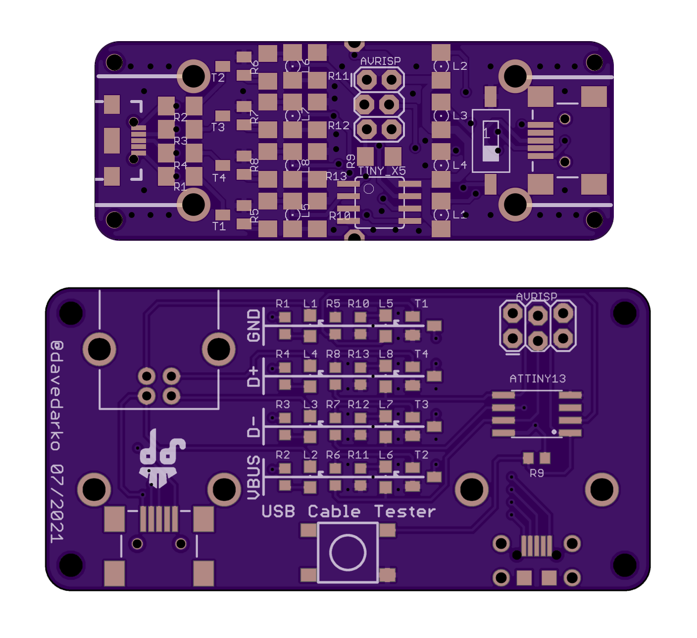
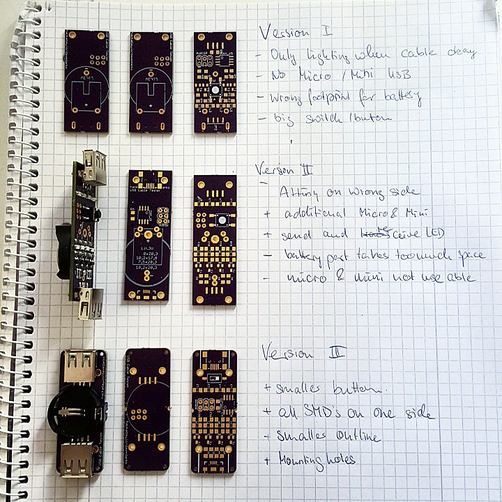
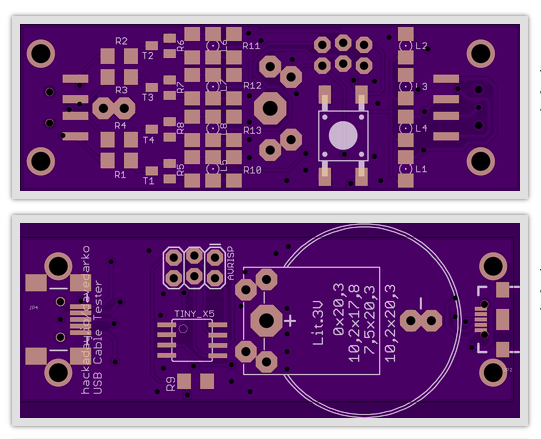
    Today I went sorting through some USB cables, but before I could test anything, I had to solder the third and last of the boards that I had ordered years ago. The micro-B USB socket held for 15 cables before I had to add glue because it got loose [log for board 2]. So I decided to update some parts on the PCB and shift things around. 

    • USB-A + micro/mini Sockets are turned 90 degrees, so you can test shorter cables
    • additional USB-B connector so you can test A-B cables
    • button is now a 6mm x 6mm sized one
    • LEDs all point in the same direction and are marked, good for soldering
    • Attiny13 was chosen as the firmware size is sub 1kB [[1kB challenge contest]]
    • swapped to SMD coin cell holder
    • changed micro-B footprint for something with 4 prongs 

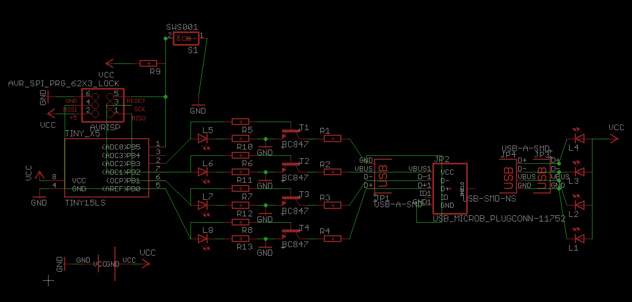
    Check out this old space ship of a schematic:

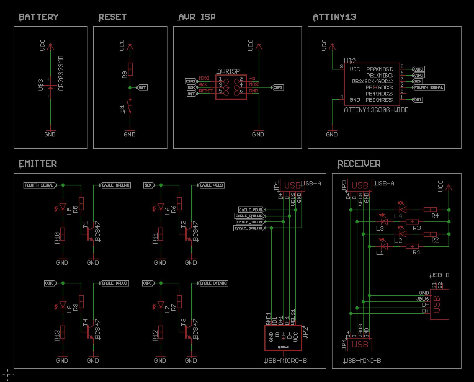
    And here is the (hopefully improved) new schematics, I think it's more readible, but not everyone is a fan of too many labels. 

    There's still one pin left on the Attiny, anyone any ideas for it?

  • yay :)

    davedarko08/26/2017 at 05:59 0 comments

    so cool to see one in the wild!

  • Board 2 is running

    davedarko12/06/2016 at 08:16 4 comments

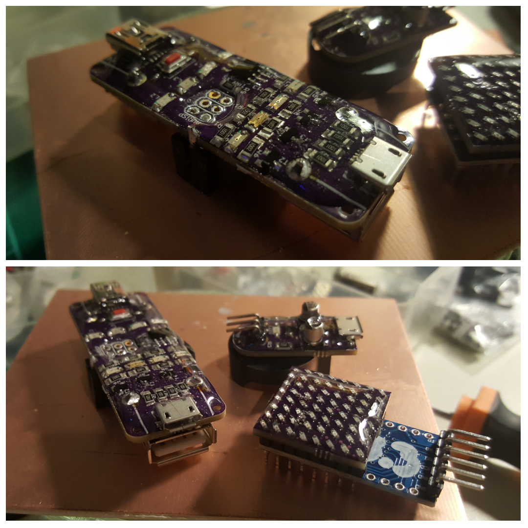
    Since the USB micro connector broke off of the first board I had to solder one again. Still have to check if the consumption still is that low and all the code really works as intended.

    Also - Resin / 2K epoxy!

  • uh wait, that fits the 1kB contest

    davedarko12/04/2016 at 13:08 0 comments

    noice! It compiles with arduino! https://hackaday.io/project/6858-usb-cable-tester/log/24876-verify-your-results

    I will test the circuit when I get home! I'm glad I just went through my projects list and that there's a USB port broken. yeah!

  • woohoo

    davedarko03/16/2016 at 16:06 0 comments

    Yay, this project got featured on the OSHPark blog :)

    http://blog.oshpark.com/2016/03/15/draft-usb-cable-tester/

  • Mark III boards are in

    davedarko09/24/2015 at 10:17 0 comments

    I'll try to toaster oven solder them in the near future.

  • verify your results

    davedarko09/09/2015 at 07:38 0 comments

    So the code from last time didn't work at all, when I woke up the blue LEDs where totally dim. I've check the datasheet for the attiny45 and noticed once again - what works on an arduino must not work on a board using non-atmega328s. I hooked up my new UNI-T UT61E and measured 200uA - not the 0.1uA I've expected to see. With the help of the gist from JChristensen I verified (read copied) my code for the power down and measured a success - yes it's measurable - 0.1uA !

    /* 
    Things to safe power, according to datasheet:
     - turn off adc (not needed for LEDs)
     - turn off brown out detection (BOD)
     - turn off analog comparator
     - turn off internal voltage reference 
     - turn off watchdog timer
     - disable port pins per register
     
    With the help of JChristensen/AVR Sleep
    https://gist.github.com/JChristensen/5616922
    
    */
    
    #include <avr/sleep.h>
    #define BODS 7                     //BOD Sleep bit in MCUCR
    #define BODSE 2                    //BOD Sleep enable bit in MCUCR
    
    int leds[] = {4,0,1,2};
    void setup() 
    {
      for (int i=0; i<4; i++)
      {
        pinMode(leds[i], OUTPUT);
        digitalWrite(leds[i], HIGH);
        delay(200);
        digitalWrite(leds[i], LOW);
        delay(200);
      }
      die_until_reset();
    }
    
    void loop() { }
    
    void die_until_reset()
    {
      byte  mcucr1, mcucr2;
    
      set_sleep_mode(SLEEP_MODE_PWR_DOWN);
      sleep_enable();
      MCUCR &= ~(_BV(ISC01) | _BV(ISC00));      //INT0 on low level
      ADCSRA &= ~_BV(ADEN);                     //disable ADC
      cli();                                    //stop interrupts to ensure the BOD timed sequence executes as required
      mcucr1 = MCUCR | _BV(BODS) | _BV(BODSE);  //turn off the brown-out detector
      mcucr2 = mcucr1 & ~_BV(BODSE);            //if the MCU does not have BOD disable capability,
      MCUCR = mcucr1;                           //  this code has no effect
      MCUCR = mcucr2;
      sleep_cpu();
    }
    

  • code and me whining and winning

    davedarko09/08/2015 at 20:21 5 comments

    Using the attiny15 footprint/part in eagle from the atmel library for the attiny45 is not right, because B4 and B3 are reversed and it's not the first time I noticed that. But this time I just went in and changed the part in the library. Muahaha. Evil, I know. PCB is updated (again), "code" is here:

    #include <avr/sleep.h>
    
    int leds[] = {0,1,2,4};
    void setup() 
    {
      for (int i=0; i<4; i++)
      {
        pinMode(leds[i], OUTPUT);
        digitalWrite(leds[i], HIGH);
        delay(200);
        digitalWrite(leds[i], LOW);
        delay(200);
      }
      set_sleep_mode(SLEEP_MODE_PWR_DOWN);
      sleep_enable();
      sleep_mode();
    }
    
    void loop() { }
    

  • this project... like... so annoying

    davedarko09/08/2015 at 12:10 3 comments

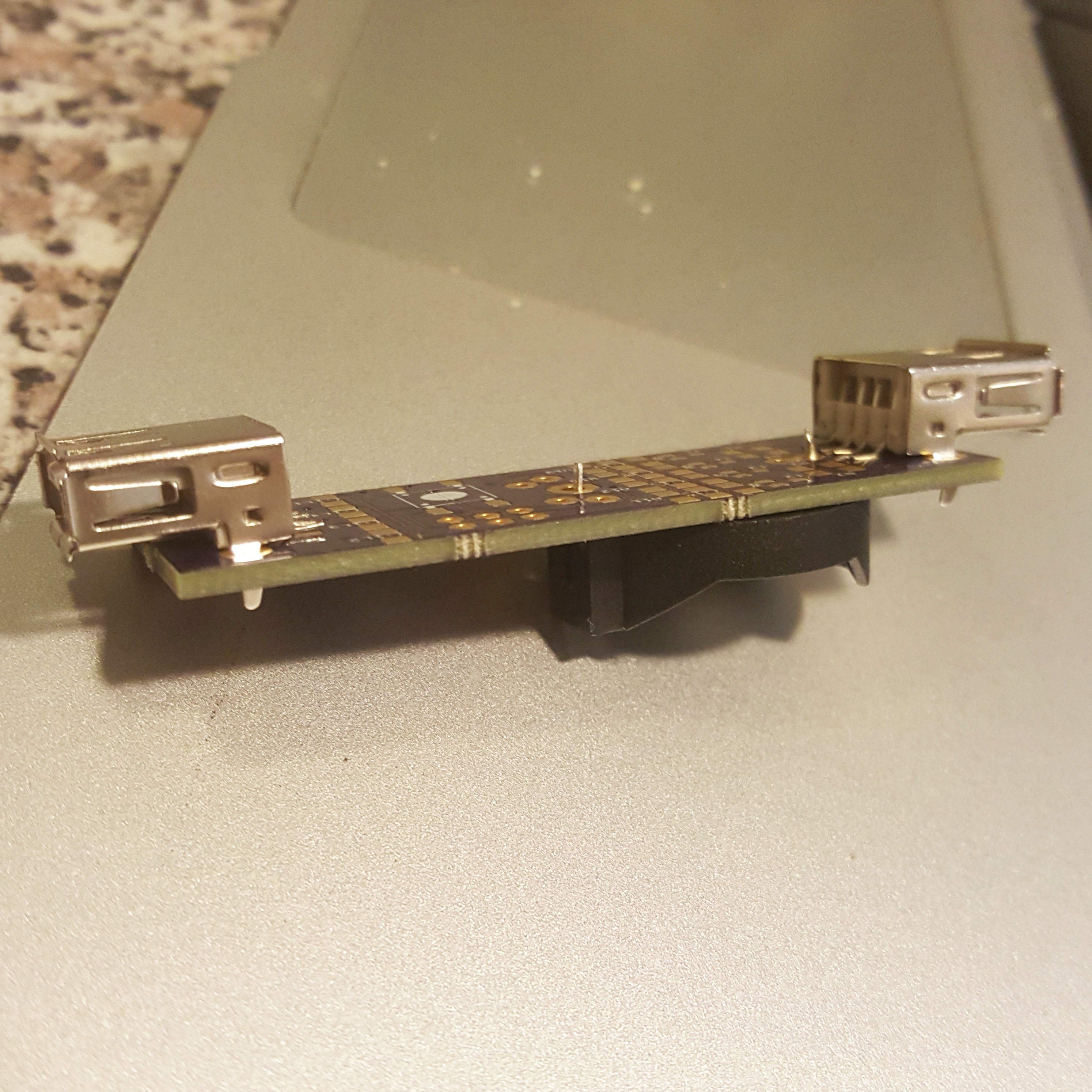
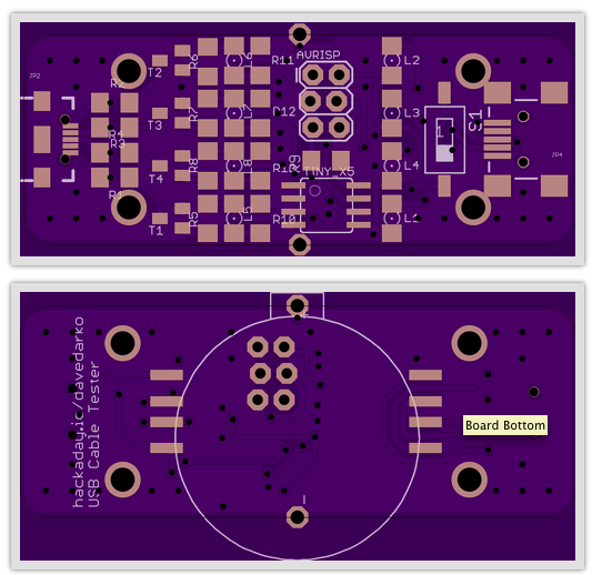
    I can't believe that I will say this, but there are some really annoying things with this design. The first and most obvious: the usb connectors and the battery connector aren't on the same side! The second one is that the connectors should be plane with the pcb, so that the micro / mini port would be useable with the USB A ports soldered on. I should stop calling designs "final".

    I "redesigned" the battery part for eagle and by turning it 90 degrees I was able to save some space.

    [UPDATE] Seems like I have connected the wrong pin of the battery holder - I took one of those 5 holes meant for plus, but not the centered one - good thing that I've redesigned that holder.

  • final design (almost)

    davedarko08/25/2015 at 19:32 0 comments

    ordered... and just saw the mistake on the silkscreen... gnargh. Anyway, don't want to neglect this project - so I ordered them.

View all 13 project logs

Enjoy this project?

Share

Discussions

Arya wrote 08/26/2017 at 19:17 point

If I were to order PCBs for this project, which ones would I need to order, and are there any ratios like "for each PCB X, order 2x PCB Y"?

  Are you sure? yes | no

davedarko wrote 08/26/2017 at 19:41 point

Hm. There should be only one that is shared, the rest is just older versions. Take the shortest roundest board :D

  Are you sure? yes | no

davedarko wrote 08/26/2017 at 19:42 point

the one in the link section is correct. There are two usb a ports, one mini and a micro on a board.

  Are you sure? yes | no

Stefan-Xp wrote 09/08/2015 at 21:42 point

Here is one proposal for you: Connect ADC2 to D+ or D-. Implement a Simple One Wire Communication ... 

1. USB cable tester 1: Send Wakeup with the Line Under Test

2. USB cable tester 2: Send Acknoledge

3. USB cable tester 1: Set the Level at the Testline to High

4. USB cable tester 2: Receive High Value

5. USB cable tester 2: Send Back the Acknoledge

6. Repeat for every Line

If Line D+ or D- is disturbed, the Cable under test couldn't be used anyhow.

BTW: Is the ICSP Connector a bit misaligned? The middle two holes seem to stick out of the row.

  Are you sure? yes | no

davedarko wrote 09/08/2015 at 22:20 point

I thought about splitting them up too, since the cable might be already installed somewhere. This could be as handy as the network testing devices (that also come with usb functionality these days?). 

The connector is one of those LOCK headers, so the pinheader wouldn't fall out while soldering. But they can also be used to program the avr without soldering the pinheader in - just plug the pinheader in and hook up your programmer... and pull it out afterwards. 

  Are you sure? yes | no

Stefan-Xp wrote 09/09/2015 at 06:41 point

Its Rather unlikely, that both Ends of a cable are at the same place?

Do you really use ordinary USB Cables under Water?

A LOCK header sounds handy. Never thought or heared of it...

  Are you sure? yes | no

davedarko wrote 09/09/2015 at 07:56 point

The Setup is somewhat complicated. There is a USB Hub in a control cabinet, where a 10m industrial usb cable is going through a - potentially filled with water - pipe/tube/hose to the RFid reader near to (and sometimes in) the water. The port to port distance might only be 4-5 meters.

Not sure where I found the LOCK headers, I think they were in the sparkfun package and I've read about them when I tried to design parts in eagle for the first time. 

  Are you sure? yes | no

Stefan Lochbrunner wrote 07/21/2015 at 16:50 point

I was wondering why you'd want to cycle through the four lines but the new details clarifies that. From the schematics and board footprints I'd say the cables you want to test are basically USB-A extensions, right? How about adding a uUSB-B jack to test those USB-A to uUSB-B cables that everyone has a ton of lying around?

  Are you sure? yes | no

davedarko wrote 07/21/2015 at 17:06 point

Indeed! I also have to be careful with those extenders, some of them have little USB hub controller chips integrated into the plug... anyway - should make another tester for these.

I will add a B port, makes sense - but also need another female port for male-A to male-A. I also have to rework the battery socket, I took a pinout for a rechargeable lithium battery that has to be soldered in directly and didn't check part availability before... 

I guess I was to fast in ordering those boards :D

  Are you sure? yes | no

Stefan Lochbrunner wrote 07/21/2015 at 17:13 point

lol, yes. I was surprised seeing this project go from a little text to ordered boards ;)

  Are you sure? yes | no

davedarko wrote 07/21/2015 at 17:13 point

rereading I noticed the little u in front of the USB - I didn't catch that the first time, but yes, the micro version should be on there.

  Are you sure? yes | no

Stefan Lochbrunner wrote 07/21/2015 at 17:19 point

I don't think USB-B is that relevant but if you can fit it on the board then why not.

  Are you sure? yes | no

Similar Projects

Does this project spark your interest?

Become a member to follow this project and never miss any updates